Open GIS Consortium, Inc.
OpenGIS
®Simple Features Specification
For OLE/COM
Revision 1.1
OpenGIS Project Document 99-050
Release Date: May 18, 1999
WARNING
: The Open GIS Consortium (OGC) releases this specification to the public without
warranty. It is subject to change without notice. This specification is currently under active revision
by the OGC Technical Committee.
Copyright 1997, 1998, 1999 Camber Corporation
Copyright 1997, 1998, 1999 Environmental Systems Research Institute Copyright 1997, 1998, 1999 Intergraph Corporation
Copyright 1997, 1998, 1999 Laser-Scan, Ltd. Copyright 1997, 1998, 1999 MapInfo Corporation Copyright 1997, 1998, 1999 Smallworldwide, plc.
The companies listed above have granted the Open GIS Consortium, Inc. (OGC) a nonexclusive, royalty-free, paid up, worldwide license to copy and distribute this document and to modify this document and distribute copies of the modified version.
Each of the copyright holders list above has agreed that no person shall be deemed to have infringed the copyright, in the included material of any such copyright holder by reason of having used the specification set forth herein or having conformed any computer software to the specification.
NOTICE
The information contained in this document is subject to change without notice.
The material in this document details an Open GIS Consortium specification in accordance with the license and notices set forth on this page. This document does not represent a commitment to implement any portion of this specification in any company’s products.
WHILE THE INFORMATION IN THIS PUBLICATION IS BELIEVED TO BE ACCURATE, THE OPEN GIS CONSORTIUM AND THE COMPANIES LISTED ABOVE MAKE NO WARRANTY OF ANY KIND WITH REGARD TO THIS MATERIAL INCLUDING, BUT NOT LIMITED TO, THE IMPLIED WARRANTIES OF MERCHANTABILITY AND FITNESS FOR A PARTICULAR PURPOSE. The Open GIS Consortium and the companies list above shall not be liable for errors contained herein or for incidental or consequential damages in connection with the furnishing, performance or use of this material.
The copyright holders list above acknowledge that the Open GIS Consortium (acting itself or through its designees) is and shall at all times be the sole entity that may authorize developers, suppliers and sellers of computer software to use certification marks, trademarks, or other special designations to indicate compliance with these materials.
This document contains information, which is protected by copyright. All Rights Reserved. No part of this work covered by copyright herein may be reproduced or used in any form or by any means⎯graphic, electronic, or mechanical, including photocopying, recording, taping, or information storage and retrieval systems⎯without permission of the copyright owner.
RESTRICTED RIGHTS LEGEND. Use, duplication, or disclosure by government is subject to restrictions as set forth in subdivision (c)(1)(ii) of the Right in Technical Data and Computer Software Clause at DFARS 252.227.7013
Table of Contents
2 ARCHITECTURE ... 2-1 2.1 DATA ACCESS... 2-1
2.1.1 OLE DB Overview ... 2-1 2.1.2 Data Providers ... 2-2 2.1.2.1 Data Provider Overview... 2-2 2.1.2.2 Requirements for Data Providers ... 2-4 2.1.3 Data Consumers (ADO) ... 2-5
2.2 GEOMETRY OBJECT MODEL... 2-6
2.2.11 MultiSurface ... 2-15 2.2.11.1 Methods ... 2-15 2.2.12 MultiPolygon ... 2-15 2.2.13 Relational Operators ... 2-17 2.2.13.1 Background... 2-17 2.2.13.2 The Dimensionally Extended Nine-Intersection Model... 2-18 2.2.13.3 Named Spatial Relationship predicates based on the DE-9IM ... 2-20
2.3 SPATIAL REFERENCE SYSTEM OBJECT MODEL... 2-24 2.4 SUMMARY... 2-25 2.4.1 Requirement summary ... 2-25
3 COMPONENT SPECIFICATIONS... 3-1 3.1 OLEDB AND ADOCOMPONENTS... 3-1
3.1.1 OGIS Data Provider Registry Entries ... 3-2 3.1.2 GIS Metadata... 3-2 3.1.3 DBSCHEMA_OGIS_FEATURE_TABLES Rowset ... 3-2 3.1.4 DBSCHEMA_OGIS_GEOMETRY_COLUMNS Rowset ... 3-3 3.1.5 DBSCHEMA_OGIS_SPATIAL_REF_SYSTEMS Rowset ... 3-4 3.1.6 OGIS Property Set ... 3-5 3.1.7 IColumnsRowset:GetColumnsRowset ... 3-6 3.1.8 Geometry ... 3-6 3.1.9 Spatial Reference... 3-7 3.1.10 Spatial Filter... 3-7 3.1.11 OGIS_Geometry Enumerated Type ... 3-8
3.2 GEOMETRY COMPONENTS—INTERFACES AND CLASSES... 3-8
3.2.4.6.2 IPolygon::get_NumInteriorRings ... 3-22 3.2.4.6.3 IPolygon::get_InteriorRing... 3-22 3.2.4.7 IGeometryCollection Interface... 3-23 3.2.4.7.1 IGeometryCollection::get_NumGeometries ... 3-23 3.2.4.7.2 IGeometryCollection::get_Geometry ... 3-23 3.2.4.8 IMultiSurface interface ... 3-24 3.2.4.8.1 IMultiSurface::get_Area... 3-24 3.2.4.8.2 IMultiSurface::get_Centroid... 3-24 3.2.4.8.3 IMultiSurface::get_PointOnSurface ... 3-24 3.2.4.9 IMultiCurve Interface ... 3-24 3.2.4.9.1 IMultiCurve::get_Length... 3-24 3.2.4.9.2 IMultiCurve::IsClosed... 3-25 3.2.4.10 ISpatialRelation Interface ... 3-25 3.2.4.10.1 ISpatialRelation::Equals... 3-25 3.2.4.10.2 ISpatialRelation::Touches ... 3-25 3.2.4.10.3 ISpatialRelation::Contains ... 3-26 3.2.4.10.4 ISpatialRelation::Within... 3-26 3.2.4.10.5 ISpatialRelation::Disjoint... 3-26 3.2.4.10.6 ISpatialRelation::Crosses ... 3-27 3.2.4.10.7 ISpatialRelation::Overlaps ... 3-27 3.2.4.10.8 ISpatialRelation::Intersects ... 3-27 3.2.4.11 ISpatialRelation2 Interface ... 3-28 3.2.4.11.1 ISpatialRelation2::Relate ... 3-28 3.2.4.12 ISpatialOperator Interface... 3-28 3.2.4.12.1 ISpatialOperator::Boundary ... 3-28 3.2.4.12.2 ISpatialOperator::Distance ... 3-28 3.2.4.12.3 ISpatialOperator::Buffer... 3-29 3.2.4.12.4 ISpatialOperator::Intersection ... 3-29 3.2.4.12.5 ISpatialOperator::Union ... 3-29 3.2.4.12.6 ISpatialOperator::Difference ... 3-30 3.2.4.12.7 ISpatialOperator::SymmetricDifference... 3-30 3.2.4.12.8 ISpatialOperator::ConvexHull... 3-30 3.2.4.13 IWks Interface ... 3-31 3.2.4.13.1 IWks::ExportToWKB ... 3-31 3.2.4.13.2 IWks::ExportToWKT... 3-31 3.2.4.13.3 IWks::ImportFromWKB ... 3-31 3.2.4.13.4 IWks::ImportFromWKT ... 3-32 3.2.4.14 IGeometryFactory Interface... 3-32 3.2.4.14.1 IGeometryFactory::CreateFromWKB ... 3-32 3.2.4.14.2 IGeometryFactory::CreateFromWKT ... 3-32 3.2.5 Exceptions, Errors, and Error Codes ... 3-33
3.3 THE WELL-KNOWN BINARY REPRESENTATION FOR GEOMETRY (WKBGEOMETRY) ... 3-33
3.3.1 Component Overview ... 3-33 3.3.2 Component Description... 3-33 3.3.2.1 Numeric Type Definitions... 3-33 3.3.2.2 XDR (Big Endian) Encoding of Numeric Types ... 3-33 3.3.2.3 NDR (Little Endian) Encoding of Numeric Types... 3-34 3.3.2.4 Conversion between the NDR and XDR representations of WKBGeometry ... 3-34 3.3.2.5 Relationship to other COM and CORBA data transfer protocols ... 3-34 3.3.2.6 Description of WKBGeometry Byte Streams ... 3-34 3.3.2.7 Assertions for Well-known Binary Representation for Geometry ... 3-36 3.3.2.8 Linear Rings... 3-37 3.3.2.9 Polygons... 3-37 3.3.2.10 MultiPolygons ... 3-37
3.4 SPATIAL REFERENCE SYSTEM COMPONENTS—INTERFACES AND CLASSES... 3-37
3.4.3.13.4 IGeographicTransform::put_TargetGCS... 3-59 3.4.3.13.5 IGeographicTransform::Forward ... 3-59 3.4.3.13.6 IGeographicTransform::Inverse ... 3-60 3.4.3.13.7 IGeographicTransform::get_ParameterInfo ... 3-60 3.4.3.14 IProjection Interface ... 3-60 3.4.3.14.1 IProjection::get_Usage ... 3-60 3.4.3.14.2 IProjection::put_Usage... 3-61 3.4.3.14.3 IProjection::get_Classification ... 3-61 3.4.3.14.4 IProjection::put_Classification... 3-61 3.4.3.14.5 IProjection::Forward ... 3-61 3.4.3.14.6 IProjection::Inverse ... 3-62 3.4.3.14.7 IProjection::get_ParameterInfo ... 3-62 3.4.3.14.8 IProjection::get_AngularUnit... 3-62 3.4.3.14.9 IProjection::put_AngularUnit... 3-63 3.4.3.14.10 IProjection::get_LinearUnit ... 3-63 3.4.3.14.11 IProjection::put_LinearUnit ... 3-63 3.4.3.14.12 IProjection::get_Ellipsoid ... 3-63 3.4.3.14.13 IProjection::put_Ellipsoid ... 3-64 3.4.3.15 IProjectedCoordinateSystem Interface ... 3-64 3.4.3.15.1 IProjectedCoordinateSystem::get_Usage ... 3-64 3.4.3.15.2 IProjectedCoordinateSystem::put_Usage... 3-64 3.4.3.15.3 IProjectedCoordinateSystem::get_GeographicCoordinateSystem ... 3-65 3.4.3.15.4 IProjectedCoordinateSystem::put_GeographicCoordinateSystem ... 3-65 3.4.3.15.5 IProjectedCoordinateSystem::get_LinearUnit... 3-65 3.4.3.15.6 IProjectedCoordinateSystem::put_LinearUnit ... 3-65 3.4.3.15.7 IProjectedCoordinateSystem::get_Projection... 3-66 3.4.3.15.8 IProjectedCoordinateSystem::put_Projection ... 3-66 3.4.3.15.9 IProjectedCoordinateSystem::get_ParameterInfo ... 3-66 3.4.3.15.10 IProjectedCoordinateSystem::Forward ... 3-66 3.4.3.15.11 IProjectedCoordinateSystem::Inverse ... 3-67 3.4.3.16 ISpatialReferenceFactory Interface ... 3-67 3.4.3.16.1 ISpatialReferenceFactory::CreateFromWKT ... 3-67 3.4.3.17 ISpatialReferenceAuthorityFactory Interface ... 3-68 3.4.3.17.1 ISpatialReferenceAuthorityFactory::get_Authority ... 3-68 3.4.3.17.2 ISpatialReferenceAuthorityFactory::CreateProjectedCoordinateSystem... 3-68 3.4.3.17.3 ISpatialReferenceAuthorityFactory::CreateGeographicCoordinateSystem ... 3-68 3.4.3.17.4 ISpatialReferenceAuthorityFactory::CreateProjection... 3-69 3.4.3.17.5 ISpatialReferenceAuthorityFactory::CreateGeographicTransform... 3-69 3.4.3.17.6 ISpatialReferenceAuthorityFactory::CreateHorizontalDatum ... 3-69 3.4.3.17.7 ISpatialReferenceAuthorityFactory::CreateEllipsoid... 3-69 3.4.3.17.8 ISpatialReferenceAuthorityFactory::CreatePrimeMeridian ... 3-70 3.4.3.17.9 ISpatialReferenceAuthorityFactory::CreateLinearUnit... 3-70 3.4.3.17.10 ISpatialReferenceAuthorityFactory::CreateAngularUnit... 3-70 3.4.4 Exceptions, Errors, and Error Codes ... 3-71
3.5 WELL-KNOWN TEXT REPRESENTATION OF SPATIAL REFERENCE SYSTEMS... 3-71
3.5.1 Component Overview ... 3-71 3.5.2 Component Description... 3-71
0 Preface
0.1 Submitting
Companies
The following companies submitted this implementation specification in response to the OGC Request 1, Open Geodata Model Working Group, A Request for Proposals: OpenGIS Features (OpenGIS Project Document Number 96-021):
• Camber Corporation
• Environmental Systems Research Institute (ESRI)
• Intergraph Corporation
• Laser-Scan, Ltd.
• MapInfo Corporation
• Smallworldwide, plc.
0.2 Submission Contact Points
All questions about the joint submission should be directed to: Ed Runnion
Camber Corporation 635 Discovery Drive Huntsville, AL 35806-2801 205-922-3590
David Beddoe ESRI National Accounts
2070 Chain Bridge Road, Suite 180 Vienna, VA 22182
(703)-506-9515
David Arctur, Ph.D. Laser-Scan, Inc. 45635 Willow Pond Plaza Sterling, VA 20164
John Reilly MapInfo Corporation One Global View Troy, NY 12180 518-285-7229
Peter Batty
Smallworld Systems, Inc. 5600 Greenwood Plaza Blvd. Englewood, CO 80111 303-779-6980
0.3 Document
Conventions
Courier New font is used to identify code segment and names.
0.4 Revision
History
Revision 1.0 includes the following changes from Revision 0:
• Replaced the term “ADC” with “RDS” and updated the accompanying text in the Overview that discusses RDS. The source for this change was proposal #1 from Revision Request 97-407.
• Adam Gawne-Cain, Cadcorp Ltd, 8th March 1999: Replaced Geometry and SpatialReference IDL code segments with latest versions. This means that potential implementors can cut/paste the definative IDL from this document Also editted descriptive text to match latest version of these IDL files.
1 Overview
The Open GIS Consortium, Inc. vision statement states that “OGC envisions the full integration of
geospatial data and geoprocessing resources into mainstream computing and the widespread use of interoperable geoprocessing software and geospatial data products throughout the information infrastructure.” (http://www.opengis.org/vision.html) The attached specification is founded in two
fundamental principles that are critical for the GIS industry to reach its goal of open geodata and geoprocessing interoperability “throughout the information infrastructure.” Those two principles are summed up in the following statement:
• The GIS database, by nature, is a fundamental component of a much larger corporate information
infrastructure, and must, therefore, integrate and leverage accepted standards for enterprise-wide information management.
In other words, the GIS is an extension of the overall corporate information system that today is
“standardized” on relational database management systems and Microsoft Windows applications. Going forward however, the database management systems being implemented may be relational, object-relational, or some yet to be determined data storage technology. Therefore, the GIS industry needs to adopt a direction that maximizes the opportunity to leverage today’s relational databases while at the same time provides a direction towards emerging data management technologies.
As an OLE/COM based proposal, current Microsoft technologies for database access were evaluated with respect to geographic information processing. These technologies included ODBC, DAO, RDO, ADO and OLE DB. ADO specifically provides the OLE Automation object oriented standards for accessing and manipulating databases, additionally OLE Automation, as a language independent technology, is quickly becoming the standard for application customization and integration. These paradigms match the needs of GIS data access quite well; GIS can, and should, be considered a database problem with the additional
requirements being geodetic coordinate systems, geometry, and graphics display. This specification
addresses these additional problems with GIS specific interfaces above and beyond the current interfaces available through current Microsoft data access technologies.
“OLE DB is a set of OLE interfaces that provide applications with uniform access to data stored in diverse information sources, regardless of location or type. These interfaces allow data sources to share their data through common interfaces without having to implement database functionality not native to the datastore.
OLE DB is a freely published specification designed with industry-wide participation through Microsoft's Open process. OLE DB is a developing industry standard for data access to and manipulation of both SQL and non-SQL data sources. This provides consistency and interoperability in an enterprise's network, from the mainframe to the desktop.”
(http://www.microsoft.com/oledb)
Going forward, Microsoft has embraced OLE DB as the foundation for data access within the OLE/COM environment. Microsoft states, “OLE DB is the fundamental Component Object Model (COM) building block for storing and retrieving records and unifies Microsoft's strategy for database connectivity. It will be used throughout Microsoft's line of applications and data stores.”
As background, Microsoft defines OLE DB as follows:
“OLE DB is a specification for a set of data access interfaces designed to enable a multitude of data stores, of all types and sizes, to work seamlessly together. These interfaces comprise an industry standard for data access and manipulation that can ensure consistency and interoperability in a heterogeneous world of data and data types.
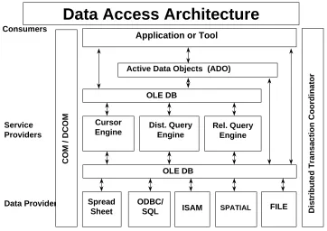
Consumers
Active Data Objects (ADO)
Figure 1.1⎯Data Access Architecture in the OLE/COM environment
The benefits of an OLE DB based OpenGIS architecture go well beyond the inherent benefits of OLE DB itself. OLE DB is a useful technology in its own right, but becomes much more powerful when leveraging other enterprise technologies provided by Microsoft and other third party developers. For example:
• Distributed Transaction Coordinator—Microsoft’s OLE-based transaction product, will utilize OLE DB for data access and makes it possible to coordinate transactions spanning multiple, diverse OLE DB data sources.
• ODBC—OLE DB data consumers, both applications and development tools, have full access to all ODBC drivers through OLE DB and the OLE DB/ODBC Provider (code named Kagera).
• Index Server—Microsoft Index Server works with Windows NT Server 4.0 and Internet Information Server 2.0 to provide your organization access to all of the documents stored on your intranet or Internet site. Index Server is an OLE DB data provider.
2 Architecture
The architecture for this specification can be classified into three major components. They are
• OLE DB for implementing data providers
• ADO for presenting a simplified data access model on top of OLE DB
• Geometry and Spatial References for detailed geometry and reference operations
Each of these components is implemented using the Microsoft Component Object Model (COM). ADO and the Geometry and Spatial Reference objects implement IDispatch and are therefore accessible to rapid development languages such as Visual Basic, Java, and Power Builder. All COM interfaces are accessible from lower level languages such as C++ for optimal performance.
2.1 Data
Access
2.1.1 OLE DB Overview
In the OLE DB specification, Microsoft writes:
OLE DB is a set of OLE interfaces that provide applications with uniform access to data stored in diverse information sources. These interfaces support the amount of DBMS functionality
appropriate to the data source, enabling it to share its data.
As such, OLE DB is an ideal interface for exposing geographic data. One of the principal advantages to exposing and consuming data via the OLE DB interface is that geographic data can then be easily integrated with other databases and office applications. It also means that a wider variety of data can also be utilized within geographic applications such as GIS. It yields a true GIS system by allowing the “G” to be tightly integrated with the corporate “IS”.
There has been no attempt to reproduce the OLE DB specification. The interested reader should consult the Microsoft OLE DB web pages or the OLE DB SDK for details.
Category Relationship to geographic applications
Data Providers Vendors of commercial GIS software should provide OLE DB data sources which expose their spatial data as well as any attribute data associated with it. Data providers or software vendors may also elect to expose government and other commercially available data sources such as DCW and Tiger.
Service Providers Geographic services may also be supplied by software vendors or end users. These services might include spatial query processors, buffer zone services, geocoding services, or network analysis services.
Consumers One of the most significant direct consumers of OLE DB is the ADO interface. The ADO interface consumes OLE DB and then projects a simpler programming model for accessing data.
Table 2.1⎯Categories of software and their relationship to geographic applications
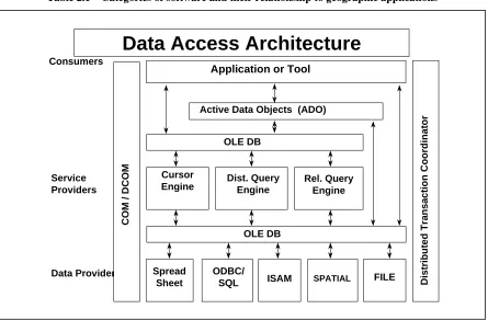
Consumers
Active Data Objects (ADO)
Figure 2.1⎯ Microsoft OLE DB Data Access Architecture
2.1.2 Data
Providers
2.1.2.1 Data Provider Overview
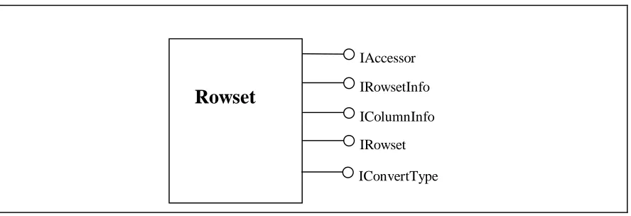
Data providers wishing to simply expose data to services and client applications are only required to implement the minimal set of OLE DB interfaces. The minimal set of interfaces for Rowsets is shown in Figure 2.2. Clients must be prepared to work with a data server that implements only the minimal set of interfaces.
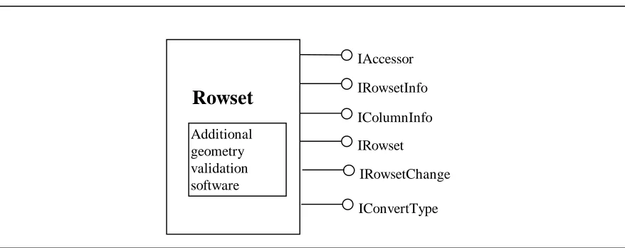
Data providers wishing to allow simple creation and modification of data must implement additional OLE DB interfaces (Figure 2.3). The data provider must always be sure that the integrity of the data is preserved according to the rules of valid data for that particular data set. One data provider may allow any geometry to be input which meets the requirements of valid OGIS data. A second data provider may require that geometric data be limited to a smaller set of geometries and be topologically clean because of a supporting topological index. This specification does not attempt to define any data validation rules others than those described in the Geometry and Spatial Reference objects.
Data providers with sophisticated relationship models may elect to expose custom COM interfaces which only allow data to be modified using a special set of operations. An example would be a data provider for parcel data (Figure 2.4). The custom interface for this may only expose methods for splitting and merging parcels. The underlying implementation may modify several tables and keep a history of the operation. Although a custom interface is used for modifying the data, the standard OLE DB interfaces should be implemented to expose the data to simpler applications such as viewers. Of course, custom interfaces could be implemented which allow more sophisticated clients to view more of the underlying data structures for analysis purposes. This specification does not attempt to describe the details of any such models or interfaces.
It is therefore clear that the OLE DB data provider interfaces scale well. They are easily extended using COM mechanisms to handle sophisticated data modeling issues.
IAccessor
Rowset
IRowsetInfoIColumnInfo IRowset IConvertType
IAccessor
Rowset
IRowsetInfoIColumnInfo IRowset
IRowsetChange Additional
geometry validation software
IConvertType
Figure 2.3⎯Minimum Rowset implementation for a data source that allows modifications
IAccessor
Rowset
IRowsetInfoIColumnInfo IRowset
IRowsetChange ( only allows attribute fields to be modified )
Parcel manipulation software Additional geometry validation software
IParcel IConvertType
Figure 2.4⎯Custom implementation for sophisticated modeling
2.1.2.2 Requirements for Data Providers
There is no strict “level of compliance” scheme for OGIS data servers. Clients are expected to use standard COM and OLE DB techniques for determining if a data server supports a specified type of functionality. It is the client’s responsibility to decide what action it will take if a data provider fails to support a given service.
The minimum level of support that a data server must pass is:
• Support the minimum set of interfaces as defined by the OLE DB standard
• Require providers to register support for the “OGISDataProvider” component category.
Data providers which do not support schema rowsets or IColumnsRowset::GetColumnsRowset are encouraged to name their geometry columns “OGIS_GEOMETRY”. Clients are also encouraged to look for columns with this name if the provider does not support the schema methods noted above.
A data provider which wishes to provide additional GIS Metadata and Geometry information to the client, should do so in compliance with Sections 3.1 and 3.2
2.1.3 Data Consumers (ADO)
ADO is a Microsoft implementation of an OLEDB data consumer. While it is not an OLEDB data provider, its purpose is to provide the essence of OLEDB data to automation clients via a standard automation server. This allows easy access to data from high level languages such as Visual Basic and Power Builder. The ADO model is analogous to, but much simpler than the OLEDB model. The fundamental objects in the ADO object hierarchy are:
• Connection—This bundles the DSO and the Session and allows the automation client to connect to the data source, access schema information and begin posing queries.
• Command—This exposes the OLEDB Command capabilities, allowing queries to be posed (Including spatial queries for OGIS data servers).
• Recordset—This is the result of a query or a request for information.
• Field—Column values that one would access via IRowset::GetData in OLEDB are accessed as the Value property of Field objects in the Recordset’s Fields collection.
Note that, via COM, the consumer can use QueryInterface to determine the capabilities of the provider. With ADO, the automation client must be prepared to catch exceptions thrown when the client attempts an activity not supported by the underlying Data Source. For example, a data provider may not support IRowsetLocate (no backwards scrolling), and so ADO’s Recordset.MovePrevious and
Recordset.Bookmark may throw exceptions. Clients should be prepared for errors so that they may work with a wide variety of data providers.
Geometry is served up through Well-known Binaries (WKB). This allows a user to then construct a geometry object or use the WKB directly. An example of code that accesses geometry is shown below.
Dim geom as IGeometry Dim rs as ADODB.Recordset Dim fld as ADODB.Field
Dim factory as IGeometryFactory Dim srs as ISpatialReference
‘ Insert code to initialise factory and srs rs.open "Schools”, connectString
set fld = rs(“OGIS_GEOMETRY”)
Do Until rs.EOF ' Do until end of recordset set geom = factory.CreateFromWKB( fld.value , srs ) AddToDisplay geom
2.2 Geometry Object Model
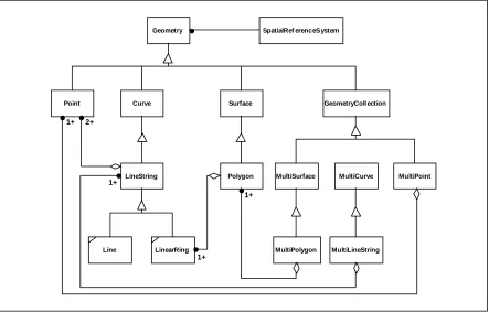
This section describes the object model for geometry. It is Distributed Computing Platform neutral and uses OMT notation. The object model for geometry is shown in Figure 2.5. The base Geometry class has subclasses for Point, Curve, Surface and Geometry Collection. Each geometric object is associated with a Spatial Reference System, which describes the coordinate space in which the geometric object is defined. Figure 2.5 is based on extending the Geometry Model specified in the OpenGIS Abstract Specification with specialized zero-, one- and two-dimensional collection classes named MultiPoint, MultiLineString and MultiPolygon for modelling geometries corresponding to collections of Points, LineStrings and Polygons respectively. MultiCurve and MultiSurface are introduced as abstract superclasses at this RFP that generalize the collection interfaces to handle Curves and Surfaces. The figure shows aggregation lines between the leaf collection classes and their element classes, the aggregation lines for non-leaf collection classes are described in the text.
The attributes, methods and assertions for each geometry class are described below. In describing methods,
this is used to refer to the receiver of the method (the object being messaged). The scope of the methods and attributes is based on the scope of RFP1 (SimpleFeatures).
MultiPoint
Figure 2.5⎯Geometry Class Hierarchy
2.2.1 Geometry
Geometry is the root class of the hierarchy. Geometry is an abstract (non-instantiable) class. All geometry objects must support the IGeometry interface.
All instantiable geometry classes described in this specification are defined so that valid instances of a geometry class are topologically closed (i.e. all defined geometries include their boundary).
2.2.1.1 Attributes of Geometry
Property Dimension As Long—The inherent dimension of this geometric object, which must be less than or equal to the coordinate dimension. This specification is restricted to geometries in two-dimensional coordinate space.
Property IsEmpty As Boolean—Returns TRUE if this geometry is the empty geometry . If true, then this geometry represents the empty point set, ∅, for the coordinate space.
Property IsSimple As Boolean—Returns TRUE if the geometry has no anomalous geometric points, such as self intersection or self tangency. The description of each instantiable geometric class will include the specific conditions that cause an instance of that class to be classified as not simple.
Property SpatialReference As ISpatialReference—Returns the Spatial Reference System for this geometry.
2.2.1.2 Basic Methods on Geometry
Function Clone() As IGeometry —Return a copy of this geometry.
Function Envelope() As IGeometry—The minimum bounding box for this geometry, returned as a geometry. The polygon is defined by the corner points of the bounding box ((MINX, MINY),(MAXX, MINY), (MAXX, MAXY), (MINX, MAXY), (MINX, MINY)).
Sub Extent2D(minX As Double, minY As Double, maxX As Double, maxY As Double) —The minimum bounding box for this geometry.
Function Project(newSystem As ISpatialReference) As IGeometry– Projects coordinates of this geometry into the specified coordinate space, returning a new geometry.
Sub SetEmpty()—Sets this geometry to the empty geometry, making this geometry represents the empty point set, ∅, for the coordinate space.
2.2.1.3 Methods for testing Spatial Relations between geometric objects :
The methods in this section are defined and described in more detail following the description of the sub types of Geometry. These methods are part of the optional ISpatialRelation interface, which geometry objects may support.
Function Contains(other As IGeometry) As Boolean— Returns TRUE if this geometry ‘spatially contains’ another geometry.
Function Crosses(other As IGeometry) As Boolean— Returns TRUE if this geometry ‘spatially crosses’ another geometry.
Function Disjoint(other As IGeometry) As Boolean— Returns TRUE if this geometry is ‘spatially disjoint’ from another geometry.
Function Intersects(other As IGeometry) As Boolean— Returns TRUE if this geometry ‘spatially intersects’ another geometry.
Function Overlaps(other As IGeometry) As Boolean— Returns TRUE if this geometry ‘spatially overlaps’ another geometry.
Function Touches(other As IGeometry) As Boolean— Returns TRUE if this geometry ‘spatially touches’ another geometry.
Function Within(other As IGeometry) As Boolean— Returns TRUE if this geometry is ‘spatially within’ another geometry.
A second optional spatial relationship interface, ISpatialRelation2, may be used for generalised spatial testing with the Relate function.
Function Relate(other As IGeometry, intersectionPatternMatrix As String) As Boolean— Returns TRUE if this geometry is spatially related to another Geometry, by testing for intersections between the Interior, Boundary and Exterior of the two geometries as specified by the values in the intersectionPatternMatrix.
2.2.1.4 Methods that support Spatial Analysis
These methods are part of the optional ISpatialOperator interface, which geometry objects may support. Function Boundary() As IGeometry)—Returns the closure of the combinatorial boundary of the geometry.. Because the result of this function is a closure, and hence topologically closed, the resulting boundary can be represented using representational geometry primitives.
Function Buffer(Distance As Double) As IGeometry—Returns a geometry that represents all points whose distance from this geometry is less than or equal to distance. Calculations are in the Spatial Reference System of this geometry.
Function ConvexHull() As IGeometry—Returns a geometry that represents the convex hull of this geometry.
Sub Difference(other As IGeometry, result As IGeometry) —Returns a geometry that represents the point set difference of the source geometry with anotherGeometry.
Function Distance(other As IGeometry) As Double—Returns the shortest distance between any two points in the two geometries as calculated in the spatial reference system of this geometry.
Sub Intersection(other As IGeometry, result As IGeometry) —Returns a geometry that represents the point set intersection of the source geometry with anotherGeometry.
Sub SymmetricDifference(other As IGeometry, result As IGeometry) —Returns a geometry that represents the point set symmetric difference of the source geometry with anotherGeometry.
2.2.2 Geometry
Collection
A GeometryCollection is a geometry that is a collection of 1 or more geometries.
All the elements in a GeometryCollection must be in the same Spatial Reference. This is also the Spatial Reference for the GeometryCollection.
GeometryCollection places no other constraints on its elements. Subclasses of GeometryCollection may restrict membership based on dimension and may also place other constraints on the degree of spatial overlap between elements.
2.2.2.1 Methods
Property NumGeometries As Long —Returns the number of geometries in the collection.
Function Geometry(index As Long) As IGeometry—Returns an indexed geometry in the collection. The indexing starts from zero.
2.2.3 Point
A Point is a 0-dimensional geometry and represents a single location in coordinate space. A point has an x-coordinate value and a y-x-coordinate value.
The boundary of a point is the empty set.
2.2.3.1 Attributes :
Property x As Double —The x-coordinate value for the point. Property y As Double —The y-coordinate value for the point.
Sub Coords(x As Double, y As Double) – the X and Y coordinates for the point
2.2.4 MultiPoint
A MultiPoint is a 0 dimensional geometric collection. The elements of a MultiPoint are restricted to Points. The points are not connected or ordered.
A MultiPoint is simple if no two Points in the MultiPoint are equal (have identical coordinate values). The boundary of a MultiPoint is the empty set.
2.2.5 Curve
A curve is a one-dimensional geometric object usually stored as a sequence of points, with the subtype of curve specifying the form of the interpolation between points. This specification defines only one subclass of curve, LineString, which uses linear interpolation between points.
A curve is simple if it does not pass through the same point twice ([1], section 3.12.7.3)
∀ c ∈ Curve, [a, b] = c.Domain,
c.IsSimple ⇔ ( ∀ x1, x2 ∈ (a, b] x1 ≠ x2 ⇒ f(x1) ≠ f (x2)) ∧ (∀ x1, x2 ∈ [a, b) x1 ≠ x2 ⇒ f(x1) ≠ f(x2))
A curve is closed if its start point is equal to its end point. ([1], section 3.12.7.3) The boundary of a closed curve is empty.
A Curve that is simple and closed is a Ring.
The boundary of a non-closed curve consists of its two end points. ([1], section 3.12.3.2). A Curve is defined as topologically closed.
2.2.5.1 Methods
Property Length As Double —The length of the curve in its associated spatial reference. Function StartPoint() As IPoint —The start point of the curve.
Function EndPoint() As IPoint —The end point of the curve.
Function Value(t As Double) As IPoint—The position of a point on the line, parameterised by length. Property IsClosed As Boolean—Returns TRUE if the curve is closed. The start point and end point of a closed curve are in the same place.
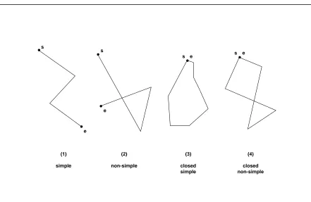
2.2.6 LineString, Line, LinearRing
A LineString is a curve with linear interpolation between points. Each consecutive pair of points defines a line segment.
A Line is a LineString with exactly 2 points.
s e
s e
s
e s
e
(1)
simple
(2)
non-simple
(3)
closed simple
(4)
closed non-simple
Figure 2.6⎯(1) a simple LineString, (2) a non-simple LineString, (3) a simple, closed LineString (a LinearRing), (4) a non-simple closed LineString
2.2.6.1 Methods
Property NumPoints As Long—The number of points in the LineString.
Function Point(index As Long) As IPoint—Returns an indexed point in the LineString. The indexing starts with zero.
2.2.7 MultiCurve
A MultiCurve is a one-dimensional GeometryCollection whose elements are Curves (Figure 2.7).
MultiCurve is a non-instantiable class in this specification, it defines a set of methods for its subclasses and is included for reasons of extensibility.
A MultiCurve is simple if and only if all of its elements are simple and the only intersections between any two elements occur at points that are on the boundaries of both elements.
The boundary of a MultiCurve is obtained by applying the “mod 2” union rule: A point is in the boundary of a MultiCurve if it is in the boundaries of an odd number of elements of the MultiCurve. ([1], section 3.12.3.2).
A MultiCurve is closed if all of its elements are closed. The boundary of a closed multicurve is always empty.
2.2.7.1 Methods
Property IsClosed As Boolean—Returns TRUE if the MultiCurve is closed
Property Length As Double—The Length of this MultiCurve which is equal to the sum of the lengths of the element Curves.
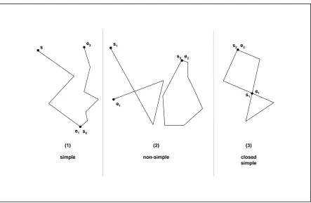
2.2.8 MultiLineString
A MultiLineString is a MultiCurve whose elements are LineStrings.
s2 e2
s1
e1
(2)
non-simple (1)
simple s
s2
e1
e2
(3)
closed simple s2 e2
s1
e1
Figure 2.7⎯(1) a simple MultiLineString, (2) a non-simple MultiLineString with 2 elements, (3) a simple, closed MultiLineString with 2 elements
The boundaries for the MultiLineStrings in Figure 2.7 are (1)⎯{s1, e2}, (2)⎯{s1, e1}, (3)⎯∅
2.2.9 Surface
A Surface is a two-dimensional geometric object.
The OpenGIS Abstract Specification defines a simple surface as consisting of a single ‘patch’ that is associated with one ‘exterior boundary’ and 0 or more ‘interior’ boundaries. Simple surfaces in three-dimensional space are isomorphic to planar surfaces. Polyhedral surfaces are formed by ‘stitching’ together simple surfaces along their boundaries, polyhedral surfaces in three-dimensional space may not be planar as a whole ([1], sections 3.12.9.1, 3.12.9.3).
The only instantiable subclass of surface defined in this specification, Polygon, is a simple surface that is planar.
2.2.9.1 Methods
Property Area As Double—The area of the surface, as measured in its spatial reference system.
Function Centroid() As IPoint—The mathematical centroid for the surface. The result is not guaranteed to be on the surface.
Function PointOnSurface() As IPoint—A point guaranteed to be on the surface.
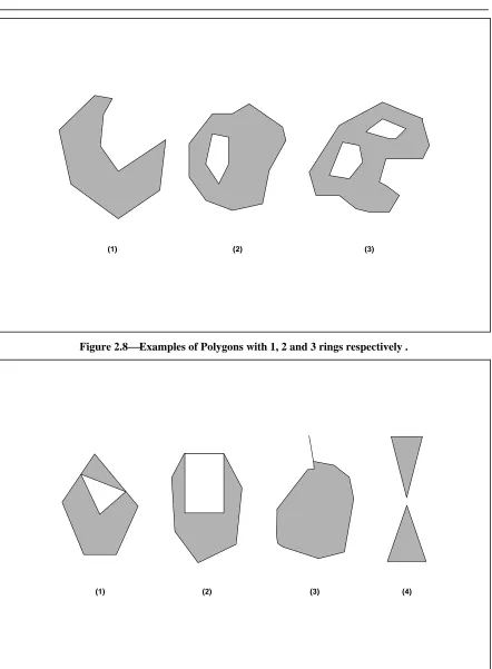
2.2.10 Polygon
A Polygon is a planar surface, defined by 1 exterior boundary and 0 or more interior boundaries. Each interior boundary defines a hole in the polygon.
The assertions for polygons (the rules that define valid polygons) are: 1. Polygons are topologically closed.
2. The boundary of a polygon consists of a set of LinearRings that make up its exterior and interior boundaries.
3. No two rings in the boundary cross, the rings in the boundary of a polygon may intersect at a point but only as a tangent :
∀ P ∈ Polygon, ∀ c1, c2 ∈ P.Boundary(), c1 ≠ c2, ∀ p, q ∈ Point, p, q ∈ c1, p ≠ q, [ p ∈ c2 ⇒ q ∉ c2]
4. A Polygon may not have cut lines, spikes or punctures: ∀ P ∈ Polygon, P = Closure(Interior(P))
5. The Interior of every Polygon is a connected point set.
6. The Exterior of a Polygon with 1 or more holes is not connected. Each hole defines a connected component of the Exterior.
In the above assertions, Interior, Closure and Exterior have the standard topological definitions. The combination of 1 and 3 make a Polygon a Regular Closed point set.
Polygons are simple geometries.
(1) (2) (3)
Figure 2.8⎯Examples of Polygons with 1, 2 and 3 rings respectively .
(1) (2) (3) (4)
2.2.10.1 Methods
Function ExteriorRing() As ILinearRing—Returns the exterior ring of the Polygon. Property NumInteriorRings As Long—Returns the number of interior rings in the Polygon.
Sub InteriorRing(index As Long, InteriorRing As ILinearRing) —Returns an indexed interior ring. The indexing starts at zero.
2.2.11 MultiSurface
A MultiSurface is a two-dimensional geometric collection whose elements are surfaces. The interiors of any two surfaces in a MultiSurface may not intersect. The boundaries of any two elements in a
MultiSurface may intersect at most at a finite number of points.
MultiSurface is a non-instantiable class in this specification, it defines a set of methods for its subclasses and is included for reasons of extensibility. The instantiable subclass of MultiSurface is MultiPolygon, corresponding to a collection of Polygons.
2.2.11.1 Methods
Property Area As Double —The area of the MultiSurface, as measured in its spatial reference system. Function Centroid() As IPoint —The mathematical centroid for the MultiSurface. The result is not guaranteed to be on the MultiSurface.
Function PointOnSurface() As IPoint —A point guaranteed to be on the MultiSurface.
2.2.12 MultiPolygon
A MultiPolygon is a MultiSurface whose elements are Polygons.. The assertions for MultiPolygons are :
1. The interiors of 2 Polygons that are elements of a MultiPolygon may not intersect. ∀ M ∈ MultiPolygon, ∀ Pi, Pj ∈ M.Geometries(), i≠j, Interior(Pi) ∩ Interior(Pj) = ∅
2. The Boundaries of any 2 Polygons that are elements of a MultiPolygon may not ‘cross’ and may touch at only a finite number of points. (Note that crossing is prevented by assertion 1 above).
∀ M ∈ MultiPolygon, ∀ Pi, Pj ∈ M.Geometries(), ∀ ci ∈ Pi.Boundaries(), cj ∈ Pj.Boundaries() ci ∩ cj = {p1, ….., pk | pi ∈ Point, 1 <= i <= k}
3. A MultiPolygon is defined as topologically closed.
4. A MultiPolygon may not have cut lines, spikes or punctures, a MultiPolygon is a Regular, Closed point set:
∀ M ∈ MultiPolygon, M = Closure(Interior(M))
The boundary of a MultiPolygon is a set of closed curves (LineStrings) corresponding to the boundaries of its element Polygons. Each curve in the boundary of the MultiPolygon is in the boundary of exactly 1 element Polygon, and every curve in the boundary of an element Polygon is in the boundary of the MultiPolygon.
The reader is referred to work by Worboys, et. al (7, 8) and Clementini, et. al (5, 6) for work on the definition and specification of MultiPolygons.
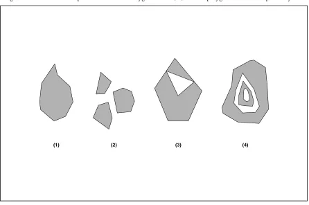
Figure 2.10 shows 4 examples of valid MultiPolygons with 1, 3, 2 and 2 polygon elements respectively.
(3) (2)
(1) (4)
Figure 2.10⎯Examples of MultiPolygons
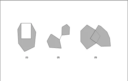
Figure 2.11 shows examples of geometric objects not representable as single instances of MultiPolygons. Note that the subclass of Surface named Polyhedral Surface described in the [1], is a faceted surface whose facets are Polygons. A Polyhedral Surface is not a MultiPolygon because it violates the rule for
(1) (2) (3)
Figure 2.11⎯Geometric objects not representable as a single instance of a MultiPolygon.
2.2.13 Relational Operators
This section provides a more detailed specification of the relational operators on geometries.
2.2.13.1 Background
The Relational Operators are Boolean methods that are used to test for the existence of a specified topological spatial relationship between two geometries. Topological spatial relationships between two geometric objects have been a topic of extensive study in the literature [4,5,6,7,8,9,10]. The basic
approach to comparing two geometries is to make pair-wise tests of the intersections between the Interiors, Boundaries and Exteriors of the two geometries and to classify the relationship between the two geometries based on the entries in the resulting ‘intersection’ matrix.
The concepts of Interior, Boundary and Exterior are well defined in general topology. For a review of these concepts the user is referred to Egenhofer, et al [4]. These concepts can be applied in defining spatial relationships between two-dimensional objects in two-dimensional space (ℜ2). In order to apply the concepts of Interior, Boundary and Exterior to 1 and 0 dimensional objects in ℜ2, a combinatorial topology approach must be applied. ([1], section. 3.12.3.2). This approach is based on the accepted definitions of the boundaries, interiors and exteriors for simplicial complexes [12] and yields the following results:
The domain of geometric objects considered is those that are topologically closed. The interior of a geometry consists of those points that are left when the boundary points are removed. The exterior of a geometry consists of points not in the interior or boundary.
Studies on the relationships between two geometries both of maximal dimension in ℜ1 and ℜ2 considered pair-wise intersections between the Interior and Boundary sets and led to the definition of a 4 Intersection Model [8]. The model was extended to consider the exterior of the input geometries, resulting in a nine intersection model [11] and further extended to include information on the dimension of the results of the pair-wise intersections resulting in a dimensionally extended nine intersection model [5]. These extensions allow the model to express spatial relationships between points, lines and areas, including areas with holes and multi component lines and areas [6].
2.2.13.2 The Dimensionally Extended Nine-Intersection Model
Given a geometry a, let I(a), B(a) and E(a) represent the Interior, Boundary and Exterior of a respectively. The intersection of any two of I(a), B(a) and E(a) can result in a set of geometries, x, of mixed dimension. For example, the intersection of the boundaries of two polygons may consist of a point and a line. Let
dim(x) return the maximum dimension (-1, 0, 1, or 2) of the geometries in x, with a numeric value of -1 corresponding to dim(∅). A dimensionally extended nine-intersection matrix (DE-9IM) then has the form:
Interior Boundary Exterior
Interior dim(I(a)∩I(b)) dim(I(a)∩B(b)) dim(I(a)∩E(b))
Boundary dim(B(a)∩I(b)) dim(B(a)∩B(b)) dim(B(a)∩E(b))
Exterior dim(E(a)∩I(b)) dim(E(a)∩B(b)) dim(E(a)∩E(b))
Table 2.2⎯The DE-9IM
For regular, topologically closed input geometries, computing the dimension of the intersection of the Interior, Boundary and Exterior sets does not have as a prerequisite the explicit computation and representation of these sets. For example to compute if the interiors of two regular closed polygons intersect, and to ascertain the dimension of this intersection, it is not necessary to explicitly represent the interior of the two polygons (which are topologically open sets) as separate geometries. In most cases the dimension of the intersection value at a cell is highly constrained given the type of the two geometries. For example, in the Line-Area case the only possible values for the Interior-Interior cell are drawn from {-1, 1} and in the Area-Area case the only possible values for the Interior-Interior cell are drawn from {-1, 2}. In such cases no work beyond detecting the intersection is required.
Interior Boundary Exterior
Interior 2 1 2
Boundary 1 0 1
Exterior 2 1 2
(a) (b)
Figure 2.12⎯An example instance and its DE-9IM
A spatial relationship predicate can be formulated on two geometries that takes as input a pattern matrix representing the set of acceptable values for the DE-9IM for the two geometries. If the spatial relationship between the two geometries corresponds to one of the acceptable values as represented by the pattern matrix, then the predicate returns TRUE.
The pattern matrix consists of a set of 9 pattern-values, one for each cell in the matrix. The possible pattern-values p are {T, F, *, 0, 1, 2} and their meanings for any cell where x is the intersection set for the cell are as follows:
p = T => dim(x) ∈{0, 1, 2}, i.e. x ≠∅
p = F => dim(x) = -1, i.e. x = ∅
p = * => dim(x) ∈ {-1, 0, 1, 2}, i.e. Don’t Care
p = 0 => dim(x) = 0
p = 1 => dim(x) = 1
p = 2 => dim(x) = 2
The pattern matrix can be represented as an array or list of nine characters in row major order. As an example the following code fragment could be used to test for “Overlap” between two areas:
char * overlapMatrix = “T*T***T**”; Geometry* a, b;
2.2.13.3 Named Spatial Relationship predicates based on the DE-9IM
The Relate predicate based on the pattern matrix has the advantage that clients can test for a large number of spatial relationships and fine tune the particular relationship being tested. It has the disadvantage that it is a lower level building block and does not have a corresponding natural language equivalent. Users of the proposed system include IT developers using the COM API from a language such as Visual Basic, and interactive SQL users who may wish, for example, to select all features ‘spatially within’ a query polygon, in addition to more spatially ‘sophisticated’ GIS developers.
To address the needs of such users a set of named spatial relationship predicates have been defined in [5,6] for the DE-9IM. The five predicates are named Disjoint, Touch, Cross, In and Overlap and have the following properties:
1. They are mutually exclusive.
2. They provide a complete covering of all topological cases.
3. They apply to spatial relationships between two geometries of either the same or different dimension. 4. Each predicate can be expressed in terms of a corresponding set of DE-9IM matrix patterns.
5. Any realizable DE-9IM can be expressed as a boolean expression over the 5 predicates, given the Boundary method on Geometry and the StartPoint and EndPoint method on Curve.
The definition of these predicates [5,6] is given below. In these definitions the term P is used to refer to 0 dimensional geometries (Points and MultiPoints), L is used to refer to one-dimensional geometries (LineStrings and MultiLineStrings) and A is used to refer to two-dimensional geometries (Polygons and MultiPolygons).
Disjoint
Given two (topologically closed) geometries a and b,
a.Disjoint(b) ⇔ a ∩ b = ∅
Expressed in terms of the DE-9IM:
a.Disjoint(b) ⇔ (I(a)∩I(b) = ∅) ∧ (I(a) ∩ B(b) = ∅) ∧ (B(a) ∩I(b) = ∅) ∧ (B(a) ∩ B(b) = ∅)
⇔ a.Relate(b, “FF*FF****”)
Touches
The Touches relation between two geometries a and b applies to the A/A, L/L, L/A, P/A and P/L groups of relationships but not to the P/P group. It is defined as:
a.Touches(b) ⇔ (I(a)∩I(b) = ∅) ∧ (a ∩ b) ≠∅
Expressed in terms of the DE-9IM:
a.Touches(b) ⇔ (I(a)∩I(b) = ∅) ∧ ( (B(a) ∩ I(b) ≠∅) ∨ (I(a) ∩B(b) ≠∅) ∨ (B(a)∩B(b) ≠∅) )
⇔ a.Relate(b, “FT*******”) ∨ a.Relate(b, “F**T*****”) ∨ a.Relate(b, “F***T****”)
Polygon/Polygon
Polygon/LineString
Polygon/Point
LineString/Point LineString/LineString
(a) (b)
1
2 1 2
(a) (b)
Figure 2.13⎯Examples of the Touch relationship
Crosses
The Crosses relation applies to P/L, P/A, L/L and L/A situations. It is defined as:
a.Crosses(b) ⇔ (dim(I(a) ∩ I(b) < max(dim(I(a)), dim(I(b)))) ∧ (a ∩ b ≠a ) ∧ (a ∩ b ≠b)
Expressed in terms of the DE-9IM:
Case a ∈ P, b ∈ L or Case a ∈ P, b ∈ A or Case a ∈ L, b ∈ A:
a.Crosses(b) ⇔ (I(a) ∩ I(b) ≠∅) ∧ (I(a) ∩ E(b) ≠∅) ⇔ a.Relate(b, “T*T******”)
Case a ∈ L, b ∈ L:
a.Crosses(b) ⇔ dim(I(a)∩I(b)) = 0 ⇔ a.Relate(b, “0********”);
Polygon/LineString
LineString/LineString
Figure 2.14⎯Examples of the Cross relationship
In (Within)
The Within relation is defined as:
a.Within(b) ⇔ (a ∩ b = a) ∧ (I(a) ∩E(b) ≠∅)
Expressed in terms of the DE-9IM:
a.Within(b) ⇔ (I(a)∩I(b) ≠∅) ∧ (I(a) ∩E(b) =∅) ∧ (B(a)∩E(b) =∅) ) ⇔ a.Relate(b, “TF*F*****”)
Polygon/Polygon
Polygon/LineString
Polygon/Point LineString/LineString
Figure 2.15⎯Examples of the Within relationship
Overlaps
The Overlaps relation is defined for A/A, L/L and P/P situations. It is defined as:
a.Overlaps(b) ⇔ (dim(I(a)) = dim(I(b)) = dim(I(a) ∩I(b))) ∧ (a ∩ b ≠ a) ∧ (a ∩ b ≠ b)
Expressed in terms of the DE-9IM: Case a ∈ P, b ∈ P or Case a ∈ A, b ∈ A:
a.Overlaps(b) ⇔ (I(a) ∩I(b)≠∅) ∧ (I(a) ∩E(b)≠∅) ∧ (E(a) ∩I(b)≠∅) ⇔ a.Relate(b, “T*T***T**”)
Case a ∈ L, b ∈ L:
a.Overlaps(b) ⇔ (dim(I(a) ∩I(b) = 1) ∧ (I(a) ∩E(b)≠∅) ∧ (E(a) ∩I(b)≠∅) ⇔ a.Relate(b, “1*T***T**”)
Polygon/LineString
LineString/LineString
Figure 2.16⎯Examples of the Overlap relationship
The following additional named predicates are also defined for user convenience: Contains
a.Contains(b) ⇔ b.Within(a)
Intersects
a.Intersects(b) ⇔! a.Disjoint(b)
2.3 Spatial Reference System Object Model
The Spatial Reference System Object Model proposed in this specification is shown in Figure 2.17. This object model is based upon the OpenGIS Abstract Specification and uses the geodetic model for spatial reference systems of the European Petroleum Survey Group (EPSG) and the Petrotechnical Open Software Corp. (POSC). Chapter 3 of this document describes the set of COM Classes and Interfaces that
Datum
HorizontalDatum
Ellipsoid Unit
LinearUnit AngularUnit
GeodeticSpatialReference
GeographicCS ProjectedCS
SpatialReference
Projection
Figure 2.17⎯The Spatial Reference System Object Model
2.4 Summary
The architecture and details contained in this specification satisfy the functional requirements of this specification subject to the detail notes in the narrative. The architecture has the following characteristics:
• Provides a COM OLE implementation consistent with OLE DB
• Easily implemented by multiple vendors
• Designed with performance in mind
• Designed with reliability and data integrity in mind
• Testable implementations
• Extensible in all key areas
2.4.1 Requirement
summary
3 Component
Specifications
3.1 OLEDB and ADO Components
ADO and OLEDB are the facilities by which consumers and providers communicate data and metadata. To achieve a sense of seamless interoperability, standards must be defined to allow GIS consumers and providers to communicate GIS information using these facilities. These standards enable an OLEDB data consumer to determine the GIS capabilities of an OLEDB data provider and retrieve GIS information in a predictable manner.
An OLEDB data consumer that cares nothing about GIS may still utilize data from an OGIS data provider as if it were any other OLEDB data provider. This consumer will simply not take advantage of the GIS information. Similarly, an OGIS data consumer can use the same OLEDB API, without the GIS standards, to utilize data from any OLEDB data provider.
These standards involve:
• OGIS Data Provider Registry Entries—OGIS data providers must register support for the "OGISDataProvider" component category so that consumers can distinguish them from other OLEDB Data Providers.
• GIS Metadata—Required and Optional GIS Metadata and the manner by which the client retrieves it are described. To a great extent, this is the bulk of the proposal—this is how the client knows there is GIS information and how to get it.
• Which tables are considered GIS features
• Which columns contain geometry; what the geometry’s spatial reference is and what type of geometry column it is.
• What the Spatial Reference(s) of the Data Source are.
• What Spatial Operators are supported by the OLEDB Data Provider
• IColumnsRowset—Additional GIS columns are defined for the Rowset returned by the
• Geometry—Methods are described for acquiring geometry from a Column or Field as a
WKBGeometry in OLEDB or a Variant in ADO.
• Spatial Reference Information—Methods are described for acquiring Spatial Reference information from the Session level as well as from the Rowset as a Variant in OLEDB or in ADO.
• Spatial Filter—Standard spatial filter parameters are defined for use with a Command in ADO and in OLEDB. Parameters are spatial filter, spatial operator and Geometry Field/Column name.
Although these standards are needed to allow GIS consumers and providers to communicate GIS
information, there is no strict "level of compliance" scheme for OGIS data servers. Clients are expected to use standard COM and OLE DB techniques for determining if a data server supports a specified type of functionality. It is up to the client to decide what action it will take if a provider does not provide that support.
The minimum level of support that a data server must pass is registering support for the "OGISDataProvider" component category.
Data providers which do not support schema rowsets or IColumnsRowset::GetColumnsRowset are encouraged to name their geometry columns "OGIS_GEOMETRY". Clients are also encouraged to look for columns with this name if the provider does not support the schema methods noted above.
A data provider which wishes to provide additional GIS Metadata and Geometry information to the client, should do so in compliance with the following sections.
3.1.1 OGIS Data Provider Registry Entries
OGIS OLEDB Data Providers must register support for the "OGISDataProvider" component category. Its GUID is CATID_OGISDataProvider1. Consumers can use this to distinguish OGIS OLEDB Data Providers.
3.1.2 GIS
Metadata
When an OLEDB data provider exposes GIS Metadata, the consumer can subsequently access and interpret data in a GIS context. This metadata is three additional SchemaRowsets and an additional
PropertySet.
3.1.3 DBSCHEMA_OGIS_FEATURE_TABLES
Rowset
This rowset indicates those tables that the consumer can query as features. Any entry in the
DBSCHEMA_OGIS_FEATURE_TABLES Rowset also appears as an entry in the standard OLEDB Tables Rowset2
.The columns in the two rowsets are different, but the rows in the standard Tables Rowset should be a superset of the rows in the DBSCHEMA_OGIS_FEATURE_TABLES Rowset.. Although there is a column for FEATURE_TABLE_ALIAS which might be exposed in a Graphical User Interface, this is not what should be used while querying. TABLE_NAME along with TABLE_CATALOG and TABLE_SCHEMA
should be used when performing database queries.
Column_Name Type_Indicator Description
1 The
FEATURE_TABLE_ALIAS DBTYPE_WSTR User Friendly Feature Name—may be NULL
TABLE_CATALOG DBTYPE_WSTR Catalog name in which the table is defined. NULL if
the provider does not support catalogs.
TABLE_SCHEMA DBTYPE_WSTR Schema name in which the Feature Table is defined,
NULL if the provider does not support schemas.
TABLE_NAME DBTYPE_WSTR Feature Table Name
ID_COLUMN_NAME DBTYPE_WSTR Preferred column name to reference rows. OGIS
requires this column to have a name3.
DG_COLUMN_NAME DBTYPE_WSTR Default Geometry column name. OGIS requires this
column to have a name.
This rowset can be accessed in OLEDB from the Session via IDBSchemaRowset::GetRowset, passing the GUID (OGIS_FEATURE_TABLES_GUID) for the DBSCHEMA_OGIS_FEATURE_TABLES Rowset. In ADO this is achieved via Connection.OpenSchema ( enum, [restrictions], [guid]). The
enum value in this case will be a specific ADO enum4 indicating that the last argument is a GUID that must be supplied by the caller and that GUID is what is passed to the OLE-DB provider. In this case it is the
OGIS_FEATURE_TABLES_GUID5.
There are no restrictions defined on the DBSCHEMA_OGIS_FEATURE_TABLES Rowset.
3.1.4 DBSCHEMA_OGIS_GEOMETRY_COLUMNS
Rowset
This rowset identifies the feature columns in the catalog which are geographic geometry. The feature identified by TABLE_CATALOG, TABLE_SCHEMA, and TABLE_NAME must appear in the
DBSCHEMA_OGIS_FEATURE_TABLES Rowset. The geometry type and spatial reference system are specified for the column.
Column_Name Type_Indicator Description
TABLE_CATALOG DBTYPE_WSTR Catalog name in which the Feature’s Table is
defined. NULL if the provider does not support catalogs.
TABLE_SCHEMA DBTYPE_WSTR Schema name in which the Feature’s Table is
defined, NULL if the provider does not support schemas.
TABLE_NAME DBTYPE_WSTR The Feature Table Name.
COLUMN_NAME DBTYPE_WSTR Name of column containing geometry
3 The use of just COLUMN_GUID and COLUMN_PROPID is not sufficient for OGIS. 4 The ADO-supplied enum for this will be available with ADO 1.5.
5
GEOM_TYPE DBTYPE_UI4 Type of geometry column. Values taken from the OGIS_Geometry Enumerated Type.
SPATIAL_REF_SYSTEM_ID DBTYPE_I4 Foreign Key—this is the ID of the Spatial
Reference System of the geometry column. This ID can be used to find the Spatial Reference in the
DBSCHEMA_OGIS_SPATIALREFERENCESYSTEMS Rowset
This rowset can be accessed from the Session via IDBSchemaRowset::GetRowset, passing the GUID (DBSCHEMA_OGIS_GEOMETRY_COLUMNS) for the DBSCHEMA_OGIS_GEOMETRY_COLUMNSRowset. In ADO this is achieved via Connection.OpenSchema (enum, [restrictions], [guid]). The enum
value in this case will be a specific ADO enum indicating that the last argument is a GUID that must be supplied by the caller and that GUID is what is passed to the OLE-DB provider. In this case it is the DBSCHEMA_OGIS_GEOMETRY_COLUMNS_GUID6.
There are no restrictions defined on the DBSCHEMA_OGIS_GEOMETRY_COLUMNS Rowset.
3.1.5 DBSCHEMA_OGIS_SPATIAL_REF_SYSTEMS
Rowset
This Rowset indicates the Spatial Reference Systems supported by the data provider in this Session. There can be more than one row in the Rowset. This Rowset contains the set of all the Spatial Reference Systems encountered for all the columns found in the DBSCHEMA_OGIS_GEOMETRY_COLUMNSRowset.
Column_Name Type_Indicator Description
SPATIAL_REF_SYSTEM_ID DBTYPE_I4 ID of the Spatial Reference System. May be NULL only if SPATIAL_REF_SYSTEM_WKT is
NULL.
AUTHORITY_NAME DBTYPE_WSTR Defining Authority for this Spatial Reference
System, e.g., “POSC”, “USGS”. May be NULL.
AUTHORITY_ID DBTYPE_I4 Authority specific identifier. This is a
Well-known id assigned to the spatial reference system by the authority. May be NULL.
SPATIAL_REF_SYSTEM_WKT DBTYPE_BSTR The Well-known Text Representation of the
Spatial Reference System. May be NULL. This rowset can be accessed from the Session via IDBSchemaRowset::GetRowset, passing the GUID (DBSCHEMA_OGIS_SPATIAL_REFERENCE) for the DBSCHEMA_OGIS_SPATIAL_REF_SYSTEMS Rowset. In ADO this is achieved via Connection.OpenSchema (enum, [restrictions], [guid]). The enum value in this case will be a specific ADO enum indicating that the last argument is a GUID that must be supplied by the caller and that GUID is what is passed to the OLE-DB provider. In this case it is the DBSCHEMA_OGIS_SPATIAL_REFERENCE7.
There are no restrictions defined on the DBSCHEMA_OGIS_SPATIAL_REF_SYSTEMS Rowset.
3.1.6 OGIS Property Set
This is a property set for OGIS specific attributes of a Data Source. This property set has GUID DPPROPSET_OGIS_SPATIAL_OPS
NOTE: Need to add two columns to table. First new column is the short description, second column is READ or READ/WRITE flag.
Property ID8 Type
Indicator
Description
DBPROP_OGIS_TOUCHES VT_BOOL All points in the intersection of geometries of
Data Source and the Spatial Filter lie on a geometry boundary and the interiors of the geometries of the Data Source and the Spatial Filter do not intersect
DBPROP_OGIS_WITHIN VT_BOOL Geometries of the Data Source are wholly
contained by the Spatial Filter.
DBPROP_OGIS_CONTAINS VT_BOOL The Spatial Filter is wholly contained by
geometries of the Data Source.
DBPROP_OGIS_CROSSES VT_BOOL Geometries of the Data Source and the Spatial
Filter intersect, but do not wholly contain each other, and the dimension of the intersection of their interiors is one less than the maximum dimension of their interiors.
DBPROP_OGIS_OVERLAPS VT_BOOL Geometries of the Data Source and the Spatial
Filter intersect and the dimension of the intersection is the same as that of the input geometries but the intersection is different than the input geometries.
DBPROP_OGIS_DISJOINT VT_BOOL Intersection of geometries of the Data Source
and the Spatial Filter is the empty set.
DBPROP_OGIS_INTERSECTS VT_BOOL Intersection of geometries of the Data Source
and the Spatial Filter is not the empty set.
DBPROP_OGIS_ENVELOPE_INTERSECT S
VT_BOOL Intersection of the envelope of geometries of
the Data Source and the envelope of the Spatial Filter is not the empty set.
DBPROP_OGIS_INDEX_INTERSECTS VT_BOOL Intersection of the spatial index entries of the
geometries of the Data Source and the geometry of the Spatial Filter is not the empty set.
3.1.7 IColumnsRowset:GetColumnsRowset
The consumer can access schema rowset information from the Session level via
IDBSchemaRowset::GetRowset. However, given a Rowset, the consumer can get specific information about that Rowset via IColumnsRowset::GetColumnsRowset without reverting to the Session. The standard columns in the IColumnsRowset are as defined by the OLEDB specification.
The OGIS Rowset consumer requires more columns than the standard IColumnsRowset or the
IColumnsInfo interfaces can provide. The IColumnsRowset::GetColumnsRowset must additionally provide all columns from the DBSCHEMA_OGIS_GEOMETRY_COLUMNS Rowset defined earlier except for
TABLE_CATALOG, TABLE_SCHEMA, TABLE_NAME, and COLUMN_NAME. Currently, that includes GEOM_TYPE
and SPATIAL_REF_SYSTEM_ID. In addition, the OGIS OLEDB data provider is obligated to provide the
SPATIAL_REF_SYSTEM_WKT from the DBSCHEMA_OGIS_SPATIALREFERENCESYSTEM Rowset that corresponds to the SPATIAL_REF_SYSTEM_ID if the consumer requests it. The consumer requests this optional column by specifying it in rgOptColumns.
For the rows corresponding to non-geometry columns the values of GEOM_TYPE and
SPATIAL_REF_SYSTEM_ID (and optional SPATIAL_REF_SYSTEM_WKT ) will be NULL.
This information is available to the ADO user by accessing Property objects in the Properties
collection for each Field off of the Recordset. If a Field has a non-NULLProperty with name
GEOM_TYPE, then it contains geometry.
3.1.8 Geometry
The consumer can determine which columns contain geometry by calling
IDBSchemaRowset::GetRowset or IColumnsRowset::GetColumnsRowset. Geometry columns should be accessible by binding to the column as DBTYPE_BYTES or as DBTYTPE_IUNKNOWN. In the latter case the requested IID must be either IID_IStream or IID_ISequentialStream.
The consumer can access geometry in a variety of ways
• C++:
• build an Accessor with a DBBINDING Structure specifying a wType as DBTYPE_BYTES or
DBTYPE_BYTES | DBTYPE_BYREF and use IRowset::GetData to access the geometry as a Well-known Binary Representation of Geometry or WKBGeometry.
• ADO:
• dim a variable as Variant and retrieve the Well-known Binary Representation of Geometry (WKBGeometry) via
variable = Field.GetChunk
In this situation ADO binds to the geometry column as DBTYPE_IUNKNOWN and requests the