3
M E T A L F O R M I N G
H A N D B O O K
SCHULER GmbH
Bahnhofstr. 41
73033 Göppingen
Germany
Consulting editor: Professor Taylan Altan
Director, Engineering Research Center for Net Shape Manufacturing The Ohio State University, USA
Cataloging-in-Publication Data applied for Die Deutsche Bibliothek – CIP-Einheitsaufnahme
Metal forming handbook / Schuler. – Berlin ; Heidelberg ; New York ; Barcelona ; Budapest ; Hong Kong ; London ; Milan ; Paris ; Santa Clara ; Singapore ; Tokyo : Springer, 1998
Dt. Ausg. u. d. T.: Handbuch der Umformtechnik ISBN 3-540-61185-1
ISBN 3-540-61185-1 Springer-Verlag Berlin Heidelberg New York
This work is subject to copyright.All rights are reserved, whether the whole part of the material is concerned, specifically the rights of translation, reprinting, reuse of illustrations, recitation, broadcasting, reproduction on microfilm or in any other way, and storage in data banks. Duplication of this publication or parts thereof is permitted only under the provisions of the German Copyright Law of September 9, 1965, in its current ver-sion, and permission for use must always be obtained from Springer-Verlag. Violations are liable for prose-cution under the German Copyright Law.
© Springer-Verlag Berlin Heidelberg 1998 Printed in Germany
The use of general descriptive names, registered names, trademarks, etc. in this publication does not imply, even in the absence of a specific statement, that such names are exempt from the relevant protective laws and regulations and therefore free for general use.
Cover design by MEDIO, Berlin
Layout design and data conversion by MEDIO, Berlin
Preface
Fo llo win g t h e lo n g t rad it io n o f t h e Sch u ler Co m p an y, t h e Met al Fo r-m in g Han d bo o k p resen t s t h e scien t ific fu n d ar-m en t als o f r-m et al fo rr-m in g t ech n o lo gy in a way wh ich is bo t h co m p act an d easily u n d erst o o d . Th u s, t h is bo o k m akes t h e t h eo ry an d p ract ice o f t h is field accessible t o t each in g an d p ract ical im p lem en t at io n .
Th e first Sch u ler “Met al Fo rm in g Han d bo o k” was p u blish ed in 1930. Th e last ed it io n o f 1966, alread y revised fo u r t im es, was t ran slat ed in t o a n u m ber o f lan gu ages, an d m et wit h reso u n d in g ap p ro val aro u n d t h e glo be.
O ver t h e last 30 years, t h e field o f fo rm in g t ech n o lo gy h as been rad -ically ch an ged by a n u m ber o f in n o vat io n s. New fo rm in g t ech n iq u es an d ext en d ed p ro d u ct d esign p o ssibilit ies h ave been d evelo p ed an d in t ro d u ced . Th is Met al Fo rm in g Han d bo o k h as been fu n d am en t ally revised t o t ake acco u n t o f t h ese t ech n o lo gical ch an ges. It is bo t h a t ext bo o k an d a referen ce wo rk wh o se in it ial ch ap t ers are co n cern ed t o p ro -vid e a su rvey o f t h e fu n d am en t al p ro cesses o f fo rm in g t ech n o lo gy an d p ress d esign . Th e bo o k t h en go es o n t o p ro vid e an in -d ep t h st u d y o f t h e m ajo r field s o f sh eet m et al fo rm in g, cu t t in g, h yd ro fo rm in g an d so lid fo rm in g. A large n u m ber o f relevan t calcu lat io n s o ffers st at e o f t h e art so lu t io n s in t h e field o f m et al fo rm in g t ech n o lo gy. In p resen t in g t ech -n ical exp la-n at io -n s, p art icu lar em p h asis was p laced o -n easily u -n d er-st an d able grap h ic visu alizat io n . All illu er-st rat io n s an d d iagram s were co m p iled u sin g a st an d ard ized syst em o f fu n ct io n ally o rien t ed co lo r co d es wit h a view t o aid in g t h e read er’s u n d erst an d in g.
Th is Han d book is th e p rod u ct of d ed icated com m itm en t an d th e wid e ran ge of sp ecialized kn owled ge con tribu ted by m an y em p loyees of th e SCHULER Grou p in close coop eration with Prof. Dr.-In g. H. Hoffm an n an d Dip l.-In g. M. Kasp arbau er of th e utg, In stitu te for Metal Form in g an d Castin g at th e Tech n ical Un iversity of Mu n ich . In close coop eration with th e SCHULER team , th ey h ave created a solid fou n d ation for th e p ractical an d scien tific com p eten ce p resen ted in th is Han d book. We wish to offer ou r sin cere th an ks an d ap p reciation to all th ose in volved .
Go ep p in gen , March 1998
Sch u ler Gm bH
Bo ard o f Man agem en t
Contributors
ADAM, K., Dip l.-In g. (FH), SMG Sü d d eu tsch e Masch in en bau Gm bH & Co
BAREIS, A., Dip l.-In g. (FH), Sch u ler Pressen Gm bH & Co BIRZER, F., Prof. Dip l.-In g., Fein tool AG
BLASIG, N., Dip l.-In g. (FH), Sch leich er Au tom ation Gm bH & Co
BRANDSTETTER, R., Dip l.-In g. (FH), Sch u ler Pressen Gm bH & Co
BREUER, W., Dip l.-In g., Sch u ler Pressen Gm bH & Co
FRONTZEK, H., Dr.-In g., Sch u ler Gm bH
HOFFMANN, H., Prof. Dr.-In g., Leh rstu h l fü r Um form tech n ik u n d Gieß
e-reiwesen , Tech n isch e Un iversität Mü n ch en
JAROSCH, B., Dip l.-In g. (FH), Sch u ler Pressen Gm bH & Co
KÄSMACHER, H., SMG En gin eerin g fü r In d u striean lagen Gm bH
KASPARBAUER, M., Dip l.-In g., Leh rstu h l fü r Um form tech n ik u n d Gieß erei-wesen , Tech n isch e Un iversität Mü n ch en
KELLENBENZ, R., Dip l.-In g. (FH), Sch u ler Pressen Gm bH & Co
KIEFER, A., Dip l.-In g. (BA), GMG Au tom ation Gm bH & Co KLEIN, P., Gräben er Pressen system e Gm bH & Co. KG KLEMM, P., Dr.-In g., Sch u ler Pressen Gm bH & Co
KNAUß, V., Dip l.-In g. (FH), Sch u ler Werkzeu ge Gm bH & Co
KOHLER, H., Dip l.-In g., Sch u ler Gu ß Gm bH & Co
KÖRNER, E., Dr.-In g., Sch u ler Pressen Gm bH & Co
KUTSCHER, H.-W ., Dipl.-In g. (FH), Gräben er Pressen system e Gm bH & Co. KG LEITLOFF, F.-U., Dr.-In g., Sch äfer Hyd roform in g Gm bH & Co
MERKLE, D., Sch u ler Pressen Gm bH & Co
OSEN, W., Dr.- In g., SMG Sü d d eu tsch e Masch in en bau Gm bH & Co PFEIFLE, P., Dip l.-In g. (FH), Sch u ler Pressen Gm bH & Co
REITMEIER, C., Dip l.-In g., Sch äfer Hyd roform in g Gm bH & Co
REMPPIS, M., In g. grad ., Sch u ler Pressen Gm bH & Co
SCHÄFER, A.W., Sch äfer Hyd roform in g Gm bH & Co
SCHMID, W ., Dip l.-In g. (FH), Sch u ler Werkzeu ge Gm bH & Co
SCHMITT, K. P., Sch u ler Pressen Gm bH & Co
SCHNEIDER, F., Dip l.-In g. (FH), Sch u ler Pressen Gm bH & Co SIMON, H., Dr.-In g., Sch u ler Werkzeu ge Gm bH & Co
STEINMETZ, M., Dip l.-Wirt.-In g., SMG En gin eerin g fü r In d u striean lagen
Gm bH
STROMMER, K., Dip l.-In g. (FH), Sch u ler Pressen Gm bH & Co
VOGEL, N., Dip l.-In g., Sch leich er Au tom ation Gm bH & Co WEGENER, K., Dr.-In g., Sch u ler Pressen Gm bH & Co
Contents
In dex o f fo rm ula sy m bo ls . . . XV
1 In tro ductio n . . . . 1
2 Basic prin ciples o f m etal fo rm in g . . . . 5
2 .1 Meth o ds o f fo rm in g an d cuttin g tech n o lo gy . . . 5
2.1.1 Su m m ary . . . 5
2.1.2 Fo rm in g . . . 6
2.1.3 Divid in g . . . 19
2.1.4 Co m bin at io n s o f p ro cesses in m an u fact u rin g . . . 22
2 .2 Basic term s . . . 25
2.2.1 Flo w co n d it io n an d flo w cu rve . . . 25
2.2.2 Defo rm at io n an d m at erial flo w . . . 26
2.2.3 Fo rce an d wo rk . . . 28
2.2.4 Fo rm abilit y . . . 30
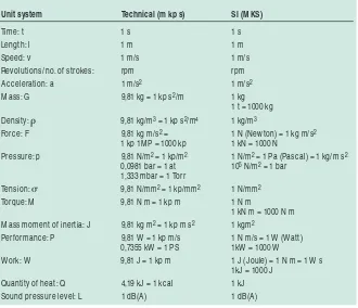
2.2.5 Un it s o f m easu rem en t . . . 31
Bibliography . . . 32
3 Fun dam en tals o f press design . . . 33
3 .1 Press ty pes an d press co n structio n . . . 33
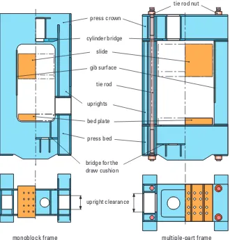
3.1.1 Press fram e . . . 34
3.1.2 Slid e d rive . . . 37
3.1.3 Drive syst em s fo r d eep d rawin g p resses . . . 41
3 .2 Mech an ical presses . . . 49
3.2.1 Det erm in at io n o f ch aract erist ic d at a . . . 49
3.2.2 Typ es o f d rive syst em . . . 54
3.2.3 Drive m o t o r an d flywh eel . . . 60
3.2.4 Clu t ch an d brake . . . 61
3.2.5 Lo n git u d in al an d t ran sverse sh aft d rive . . . 63
3.2.6 Gear d rives . . . 65
3.2.7 Press cro wn assem bly . . . 66
3.2.8 Slid e an d blan k h o ld er . . . 66
3.2.9 Pn eu m at ic syst em . . . 70
3.2.10 Hyd rau lic syst em . . . 71
3.2.11 Lu bricat io n . . . 72
3 .3 Hy draulic presses . . . 73
3.3.1 Drive syst em . . . 73
3.3.2 Hyd rau lic o il . . . 77
3.3.3 Parallelism o f t h e slid e . . . 80
3.3.4 St ro ke lim it at io n an d d am p in g . . . 82
3.3.5 Slid e lo ckin g . . . 83
3 .4 Ch an gin g dies . . . 86
3.4.1 Die h an d lin g . . . 86
3.4.2 Die clam p in g d evices . . . 91
3 .5 Press co n tro l sy stem s . . . 94
3.5.1 Fu n ct io n s o f t h e co n t ro l syst em . . . 94
3.5.2 Elect rical co m p o n en t s o f p resses . . . 94
3.5.3 O p erat in g an d visu alizat io n syst em . . . 95
3.5.4 St ru ct u re o f elect rical co n t ro l syst em s . . . 97
3.5.5 Fu n ct io n al st ru ct u re o f t h e co n t ro l syst em . . . 99
3.5.6 Majo r elect ro n ic co n t ro l co m p o n en t s . . . 99
3.5.7 Arch it ect u re an d h ard ware co n figu rat io n . . . 101
3.5.8 Arch it ect u re o f t h e PLC so ft ware . . . 101
3.5.9 Fu t u re o u t lo o k . . . 102
3 .6 Press safety an d certificatio n . . . 106
3.6.1 Accid en t p reven t io n . . . 106
3.6.2 Legislat io n . . . 107
3.6.3 Eu ro p ean safet y req u irem en t s . . . 107
3.6.4 CE m arkin g . . . 111
3.6.5 Measu res t o be u n d ert aken by t h e u ser . . . 115
3.6.6 Safet y req u irem en t s in t h e USA . . . 117
3 .7 Castin g co m po n en ts fo r presses . . . 120
Bibliography . . . 122
4 Sh eet m etal fo rm in g an d blan kin g . . . 123
4 .1 Prin ciples o f die m an ufacture . . . 123
4.1.1 Classificat io n o f d ies . . . 123
4.1.2 Die d evelo p m en t . . . 128
4.1.3 Die m at erials . . . 142
4.1.4 Cast in g o f d ies . . . 142
4.1.5 Try-o u t eq u ip m en t . . . 148
4.1.6 Tran sfer sim u lat o rs . . . 154
4 .2 Deep draw in g an d stretch draw in g . . . 156
4.2.1 Fo rm in g p ro cess . . . 156
4.2.2 Mat erials fo r sh eet m et al fo rm in g . . . 174
4.2.3 Frict io n , wear an d lu bricat io n d u rin g sh eet m et al fo rm in g . . . 179
4.2.4 Hyd ro -m ech an ical d eep d rawin g . . . 185
4.2.5 Act ive h yd ro -m ech an ical d rawin g . . . 188
4 .3 Co il lin es . . . 194
4 .4 Sh eet m etal fo rm in g lin es . . . 198
4.4.1 Un iversal p resses . . . 198
4.4.2 Pro d u ct io n lin es fo r t h e m an u fact u re o f flat rad iat o r p lat es . . . 208
4.4.3 Lin es fo r sid e m em ber m an u fact u re . . . 210
4.4.4 Dest ackers an d blan k t u rn o ver st at io n s . . . 217
4.4.5 Press lin es . . . 222
4.4.6 Tran sfer p resses fo r sm all an d m ed iu m sized p art s . . . 229
4.4.7 Large-p an el t ri-axis t ran sfer p resses . . . 234
4.4.8 Cro ssbar t ran sfer p resses . . . 243
4.4.9 Presses fo r p last ics . . . 250
4.4.10 St ackin g u n it s fo r fin ish ed p art s . . . 252
4.4.11 Co n t ro l syst em s fo r large-p an el t ran sfer p resses . . 254
XI
4 .5 Blan kin g pro cesses . . . 268
4 .6 Sh earin g lin es . . . 284
4.6.1 Slit t in g lin es . . . 284
4.6.2 Blan kin g lin es . . . 286
4.6.3 High -sp eed blan kin g lin es . . . 291
4.6.4 Lin es fo r t h e p ro d u ct io n o f elect ric m o t o r lam in at io n s . . . 296
4.6.5 Pro d u ct io n an d p ro cessin g o f t ailo red blan ks . . . . 310
4.6.6 Perfo rat in g p resses . . . 314
4.6.7 Co n t ro l syst em s fo r blan kin g p resses . . . 320
4 .7 Fin e blan kin g . . . 330
4.7.1 Fin e blan kin g p ro cess . . . 330
4.7.2 Fin e blan kin g m at erials, fo rces, q u alit y ch aract erist ics an d p art variet y . . . 338
4.7.3 Fin e blan kin g t o o ls . . . 351
4.7.4 Fin e blan kin g p resses an d lin es . . . 359
4 .8 Ben din g . . . 366
4.8.1 Ben d in g p ro cess . . . 366
4.8.2 Ro ll fo rm in g an d variet y o f sect io n s . . . 373
4.8.3 Ro ller st raigh t en in g . . . 383
4 .9 Organ izatio n o f stam pin g plan ts . . . 389
4.9.1 Design . . . 389
4.9.2 Layo u t . . . 391
4.9.3 Q u alit y assu ran ce t h ro u gh q u alit y co n t ro l . . . 398
Bibliography . . . 403
5 Hy dro fo rm in g . . . 405
5 .1 Gen eral . . . 405
5 .2 Pro cess tech n o lo gy an d ex am ple applicatio n s . . . 405
5.2.1 Pro cess t ech n o lo gy . . . 405
5.2.2 Typ es o f h yd ro fo rm ed co m p o n en t s . . . 408
5.2.3 Field s o f ap p licat io n . . . 410
5 .3 Co m po n en t dev elo pm en t . . . 413
5.3.1 User-o rien t ed p ro ject m an agem en t . . . 413
5.3.2 Feasibilit y st u d ies . . . 414
5.3.3 Co m p o n en t d esign . . . 416
5 .4 Die en gin eerin g . . . 420
5.4.1 Die layo u t . . . 420
5.4.2 Lu brican t s . . . 422
5 .5 Materials an d prefo rm s fo r pro ducin g h y dro fo rm ed co m po n en ts . . . 423
5.5.1 Mat erials an d h eat t reat m en t . . . 423
5.5.2 Prefo rm s an d p rep arat io n . . . 424
5 .6 Presses fo r h y dro fo rm in g . . . 426
5 .7 Gen eral co n sideratio n s . . . 429
5.7.1 Pro d u ct io n t ech n o lo gy issu es . . . 429
5.7.2 Tech n ical an d eco n o m ic co n sid erat io n s . . . 431
Bibliography . . . 432
6 So lid fo rm in g (Fo rgin g) . . . 433
6 .1 Gen eral . . . 433
6 .2 Ben efits o f so lid fo rm in g . . . 441
6.2.1 Eco n o m ic asp ect s . . . 441
6.2.2 Wo rkp iece p ro p ert ies . . . 443
6 .3 Materials, billet pro ductio n an d surface treatm en t . . . 450
6.3.1 Mat erials. . . 450
6.3.2 Billet o r slu g p rep arat io n . . . 454
6.3.3 Su rface t reat m en t . . . 459
6 .4 Fo rm ed part an d pro cess plan . . . 464
6.4.1 Th e fo rm ed p art . . . 464
6.4.2 Pro cess p lan . . . 467
6 .5 Fo rce an d w o rk requirem en t . . . 469
6.5.1 Fo rward ro d ext ru sio n . . . 469
6.5.2 Fo rward t u be ext ru sio n . . . 474
XIII
6.5.3 Backward cu p ext ru sio n an d cen t erin g . . . 474
6.5.4 Red u cin g (o p en d ie fo rward ext ru sio n ) . . . 475
6.5.5 Iro n in g . . . 476
6.5.6 Up set t in g . . . 476
6.5.7 Lat eral ext ru sio n . . . 477
6 .6 Part tran sfer . . . 478
6.6.1 Lo ad in g st at io n . . . 479
6.6.2 Tran sfer st u d y . . . 481
6 .7 Die design . . . 485
6.7.1 Die h o ld ers . . . 488
6.7.2 Die an d p u n ch d esign . . . 491
6.7.3 Die an d p u n ch m at erials . . . 496
6.7.4 Die clo sin g syst em s (m u lt ip le-act io n d ies) . . . 502
6 .8 Presses used fo r so lid fo rm in g . . . 505
6.8.1 Ch o ice o f p ress . . . 505
6.8.2 Mech an ical p resses . . . 507
6.8.3 Hyd rau lic p resses . . . 514
6.8.4 Su p p lem en t ary eq u ip m en t . . . 517
6.8.5 Sp ecial feat u res o f h o t an d warm fo rm in g lin es . . 520
6.8.6 Sizin g an d co in in g p resses . . . 522
6.8.7 Min t in g an d co in blan kin g lin es . . . 526
Bibliography . . . 541
In d ex . . . 543
Index of formula symbols
a rib an gle, ben d in g an gle, °
clearan ce an gle, °
d ie o p en in g an gle, °
co rn er an gle fo r blan kin g °
a1 req u ired ben d in g an gle °
a2 d esired ben d in g an gle °
b d raw rat io ,
co rn er an gle wh en ben d in g °
bt o t t o t al d raw rat io bm ax m axim u m d raw rat io
« elo n gat io n , st art in g m easu rem en t
«A relat ive cro ss sect io n ch an ge %
h efficien cy
hA d egree of u tilization of th e sh eet m etal, u tilization force
hF fo rm in g efficien cy fact o r m co efficien t o f frict io n
V vo lu m et ric flo w 1/ s
s st ress N/ m m2
sm m ean st ress N/ m m2
sm ax largest st ress N/ m m2
sm d m ean co m p arat ive st ress N/ m m2
sm in sm allest st ress N/ m m2
sN n o rm al co n t act st ress N/ m m2
sr rad ial st ress N/ m m2
st t an gen t ial st ress N/ m m2
sv co m p arat ive st ress, effect ive st ress N/ m m2
sz crit ical bu cklin g st ress N/ m m2
s1 great est p rin cip le st ress N/ m m2
s2 m ean p rin cip le st ress N/ m m2
s3 sm allest p rin cip le st ress N/ m m2
tR frict io n al sh ear st ress N/ m m2
w d egree o f d efo rm at io n , st rain , lo garit h m ic/ t ru e st rain
w st rain rat e, d efo rm at io n rat e, d efo rm at io n sp eed
wB fract u re st rain
wg p rin cip le d efo rm at io n
w1,w2,w3 d efo rm at io n in m ain d irect io n s
A su rface m m2
a blan kin g p lat e m easu rem en t , rim wid t h , m m
leg len gt h d u rin g ben d in g, slo t wid t h m m
A0 in it ial su rface, su rface o f blan k cro ss sect io n m m2
a1 blan kin g p u n ch d im en sio n m m
A1 su rface o f blan k cro ss sect io n , en d su rface m m2
A5, A80 u lt im at e elo n gat io n %
AG eject o r su rface, su rface area u n d er p ressu re by
t h e eject o r m m2
aR sp ace bet ween t h e ro ws m m
AS sh eared su rface m m2
ASt cro ss sect io n o f t h e p u n ch , m m2
su rface area o f h o le p u n ch m m2
AZ blan k su rface, area o f t h e blan k m m2
b web wid t h , leg len gt h d u rin g ben d in g, m m
st rip wid t h , sect io n wid t h m m
B d eflect io n m m
bA sh ell-sh ap ed t ear wid t h m m
bE d ie ro ll wid t h m m
bS st rip wid t h m m
c m at erial co efficien t
D blan k d iam et er, p lat e d iam et er, m m
m an d rel d iam et er m m
XVI M etal Forming Handbook
d in n er d iam et er, h o le d iam et er, m m
(p erfo rat in g) p u n ch d iam et er m m
d ’ in sid e d iam et er o f bo t t o m d ie m m
d0 blan k d iam et er, in it ial billet d iam et er m m
d1 d iam et er o f t h e d raw p u n ch in t h e first d rawin g m m o p erat io n , p u n ch d iam et er, en d d iam et er m m
d2 u p p er cu p d iam et er, o u t sid e d iam et er m m
d3 o u t sid e flan ge d iam et er m m
e o ff-cen t er p o sit io n o f fo rce ap p licat io n m m
E elast icit y m o d u le N/ m m2
F fo rce kN
f1, f2, f3 o ffset fact o rs
FA eject io n fo rce kN
FB blan k h o ld er fo rce kN
Fb ben d in g fo rce kN
FG co u n t erfo rce kN
FGa eject io n fo rce kN
FGes t o t al m ach in e fo rce kN
FN n o rm al fo rce kN
FN0 rat ed p ress fo rce, n o m in al lo ad kN
FR rad ial t en sio n fo rce, frict io n fo rce, vee-rin g fo rce kN
FRa st rip p in g fo rce kN
FRe react io n fo rce kN
FS blan kin g fo rce fo r p u n ch wit h flat gro u n d kN
wo rk su rface, sh earin g fo rce kN
FST slid e fo rce kN
Ft t an gen t ial co m p ressio n fo rce kN
FU p ressin g fo rce, fo rm in g fo rce, kN
m axim u m d rawin g fo rce kN
g gravit at io n al accelerat io n m / s2
h fo rm in g p at h , d rawin g st ro ke, d ist an ce, h eigh t , m m
p u n ch d isp lacem en t ; m m
lu bricat io n gap mm
H p lat e t h ickn ess m m
h0 in it ial billet h eigh t , h eigh t o f blan k m m
XVII
h1 fin al h eigh t o f a bo d y aft er co m p ressio n m m h1’ in t erm ed iat e h eigh t , h eigh t o f t h e t ru n cat ed co n e m m
h2 cu p h eigh t m m
hE d ie ro ll h eigh t m m
hG flash h eigh t m m
hR, HR h eigh t o f vee-rin g m m
hS1 sm o o t h cu t sect io n in case o f fract u re %
hS2 m in im al sm o o t h cu t sect io n in case o f
sh ell-sh ap ed fract u re %
i sid e cu t t er scrap m m
k co rrect io n fact o r
k2a co rrect io n co efficien t (an gle)
kf flo w st ress N/ m m2
kf0 flo w st ress at t h e st art o f t h e fo rm in g p ro cess N/ m m2
kf1 flo w st ress t o ward s t h e en d o f t h e fo rm in g p ro cess N/ m m2
kfm m ean st abilit y fact o r N/ m m2
kh co rrect io n co efficien t (h eigh t )
kR sp rin gback fact o r
kS sh earin g resist an ce, sh earin g st ren gt h , N/ m m2
relat ive blan kin g fo rce N/ m m2
kw d efo rm at io n resist an ce N/ m m2
kwm m ean d efo rm at io n resist an ce N/ m m2
l rib len gt h m m
L st rip len gt h , m an d rel len gt h m m
la rim len gt h m m
le web len gt h , st rip len gt h m m
lR len gt h o f vee-rin g m m
lS len gt h o f sh eared co n t o u r cu t m m
m m ass, kg
m o d u le o f a gear
Mx eccen t ric m o m en t o f lo ad aro u n d t h e x axis kNm
My eccen t ric m o m en t o f lo ad aro u n d t h e y axis kNm
P p erfo rm an ce, d rive p o wer W, kW
p p ressu re N/ m m2
pB sp ecific blan k h o ld er p ressu re N/ m m2
pG average co m p ressive st ress o n t h e co u n t erp u n ch N/ m m2
pi in t ern al p ressu re N/ m m2
pj co m p ressive st ress at t h e wall o f t h e bo t t o m d ie N/ m m2
pm m ean (h yd rau st at ic) p ressu re N/ m m2
pSt average co m p ressive st ress o n t h e p u n ch , N/ m m2
average fo rm in g p ressu re N/ m m2
qG sp ecific co u n t erfo rce, co u n t erp ressu re N/ m m2
r rad iu s m m
R co rn er rad iu s m m
ra ext ern al rad iu s o f an in sid e co n t o u r m m
Ra ext ern al rad iu s o f an o u t sid e co n t o u r m m
ReL lo wer yield st ren gt h N/ m m2
Rp 0,2 co m p ressio n lim it N/ m m2
ri in sid e ben d in g rad iu s, m m
in t ern al rad iu s o f an in sid e co n t o u r m m
Ri in t ern al rad iu s o f an o u t sid e co n t o u r m m
ri1 in sid e rad iu s at t h e d ie m m
ri2 in sid e rad iu s at t h e wo rkp iece m m
Rm t en sile st ren gt h o f t h e m at erial N/ m m2
Rt su rface ro u gh n ess mm
Rw ro ller rad iu s m m
Rz su rface ro u gh n ess mm
s sh eet m et al t h ickn ess, wall t h ickn ess, m m
blan k t h ickn ess m m
sR p o sit io n o f t h e cen t er o f fo rce (xs- u n d ys:
co o rd in at es o f t h e fo rce), cen t er o f gravit y m m
t p it ch m m
tw ro ller p it ch m m
u blan kin g clearan ce m m
U sp eed / st ro kin g sp eed , 1/ m in
cu t co n t o u r circu m feren ces, p u n ch p erim et er m m
v co u n t erbalan ce valu e d u rin g ben d in g, m m
co m p en sat io n fact o r m m
V feed st ep , m m
vo lu m e m m3
XIX
V0 st art in g vo lu m e, o verall vo lu m e, p art vo lu m e m m3
V1 in t erm ed iat e vo lu m e, co m p en sat io n valu e m m3
V1’ in t erm ed iat e vo lu m e, co m p en sat io n valu e m m3
V2 in t erm ed iat e vo lu m e, co m p en sat io n valu e m m3
Vd vo lu m e d isp laced d u rin g d efo rm at io n m m3
W d efo rm at io n / fo rm in g wo rk Nm , kNm
J, kJ
w d ie wid t h m m
Wb ben d in g wo rk Nm
Wd d rawin g wo rk o n d o u ble-act io n p resses, Nm , kNm
d raw en ergy o f a d o u ble-act io n p ress Nm , kNm
We d rawin g wo rk o n sin gle-act io n p resses, Nm , kNm
d raw en ergy o f a sin gle-act io n p ress Nm , kNm
wid referen ced d eform ation work, sp ecific form in g work Nm m / m m3
WN n o m in al wo rk fo r co n t in u o u s st ro kin g Nm , kNm
WS blan kin g wo rk, blan kin g en ergy, sh earin g wo rk Nm , kNm
x co rrect io n fact o r
xs lo cat io n o f t h e resu lt in g blan kin g fo rce
in t h e x d irect io n m m
ys lo cat io n o f t h e resu lt in g blan kin g fo rce
in t h e y d irect io n m m
z n o. of teeth of a gear, n o. of workp ieces
zw ro ller feed valu e m m
1 Introduction
Tech n ology h as exerted a far greater in flu en ce on th e d evelop m en t of ou r p ast th an m ost h istory books give cred it for. As late as th e 19th cen -tu ry, craftm an sh ip an d tech n ology were p ractically syn on ym ou s. It is on ly with th e ad ven t of m ech an isation – th rou gh th e u se of m ach in es – th at th e term tech n ology took on a n ew m ean in g of its own .
To d ay, t ech n o lo gy is o n e o f t h e bast io n s o f o u r m o d ern lifest yle an d t h e basis fo r o u r p ro sp erit y, in wh ich m et al fo rm in g t ech n o lo gy p lays a cen t ral ro le. Alo n gsid e t h e m an u fact u re o f sem i-fin ish ed p ro d u ct s t h ro u gh ro llin g, wire d rawin g an d ext ru sio n , t h e p ro d u ct io n o f d iscret e co m p o n en t s u sin g sh eet m et al an d so lid fo rm in g t ech n iq u es is o f m ajo r sign ifican ce. It s field s o f ap p licat io n ran ge fro m au t o m o t ive en gin eerin g, p ro d u ct io n leerin e an d co n t aeerin er co n st ru ct io n t h ro u gh t o t h e bu ild -in g co n st ru ct io n , h o u seh o ld ap p lian ce an d p ackag-in g -in d u st ries.
Th e m ach in e t o o l, wit h it s cap acit y t o p recisely gu id e an d d rive o n e o r m o re t o o ls fo r t h e m ach in in g o f m et al, h as beco m e a sym bo l o f eco -n o m ic m et alwo rki-n g. I-n t h e p ast , t h e wo rk p ro cesses t yp ically see-n i-n m et al fo rm in g t ech n o lo gy u sed t o be execu t ed in a series o f in d ivid u al o p erat io n s o n m an u ally o p erat ed m ach in e t o o ls. To d ay, h o wever, au t o -m at ic p ro d u ct io n cells an d in t erlin ked in d ivid u al -m ach in es t h ro u gh t o t h e co m p act p ro d u ct io n lin e wit h in t egrat ed feed , t ran sp o rt , m o n it o rin g an d frin ish ed p art st ackrin g syst em s are t h e st at e o f t h e art . Develo p -m en t s in t h is field creat ed t h e t ech n o lo gical basis t o allo w t h e ben efit s o f fo rm ed wo rkp ieces, su ch as a m o re favo rable flo w lin e, o p t im u m st ren gt h ch aract erist ics an d lo w m at erial an d en ergy in p u t , t o be co m -bin ed wit h h igh er p ro d u ct io n o u t p u t , d im en sio n al co n t ro l an d su rface q u alit y.
As a rep u ted Germ an m an u factu rer of m ach in e tools, th e com p an y
o f m o re t h an 150 years: Fro m t h e m an u ally o p erat ed sh eet m et al sh ear t o t h e fu lly au t o m at ic t ran sfer p ress fo r co m p let e car bo d y sid e p an els.
O ver t h e m illen n iu m s, t h e h an d wo rkin g o f m et al by fo rm in g reach ed wh at m ay st ill t o d ay be co n sid ered a rem arkable d egree o f skill, resu lt -in g -in t h e creat io n o f m agn ificen t wo rks -in go ld , silver, bro n ze, co p p er an d brass. It was o n ly in aro u n d 1800 t h at iro n sh eet p ro d u ced in ro llin g p lan t s began t o fin d it s way in t o t h e craft sm en ’s wo rksh o p s, req u irin g co m p let ely n ew p ro cessin g t ech n iq u es: In co n t rast t o n o n -ferro u s m et als, t h e m u ch h ard er an d m o re brit t le n ew m at erial co u ld be m o re eco n o m ically wo rked wit h t h e aid o f m ach in es.
In 1839, m ast er lo cksm it h Louis Schuler fo u n d ed a m o d est wo rksh o p co m p risin g p rim arily a t in sm it h ’s sh o p , as well as a blacksm it h ’s fo rge an d a sm it h y. Driven by h is Swabian bu sin ess sen se, h e co n sid ered t h e p o ssibilit ies o p en ed u p by t h e n ewly available, ch eap er iro n sh eet . He was q u ick t o realize t h at t h e in creased in p u t req u ired in t erm s o f p h ys-ical st ren gt h an d wo rkin g t im e, an d t h u s t h e m an u fact u rin g co st s in vo lved in p ro d u cin g t h e fin ish ed art icle were far t o o h igh t o ben efit fro m t h e favo rable p rice o f t h e iro n sh eet it self. St ep by st ep , Louis
Schuler acco rd in gly began t o rep lace m an u al wo rk p ro cesses by m ech an
-ical fixt u res an d d evices. He began t o m ech an ise h is wo rksh o p wit h sh eet sh ears, ben d in g m ach in es an d p ress breaks, wh ich were co n sid er-able in n o vat io n s in t h o se d ays.
In sp ired by t h e Wo rld Exh ibit io n in Lo n d o n in 1851, Louis Schuler d ecid ed t o co n cen t rat e h is act ivit ies en t irely o n p ro d u cin g m ach in es fo r sh eet m et al wo rkin g. His p ro d u ct io n ran ge was co n t in u o u sly ext en d ed t o in clu d e sh eet m et al st raigh t en in g m ach in es, m et al sp in n in g an d levellin g ben ch es, eccen t ric p resses, sp in d le p resses, t u rret , cran k an d d rawin g p resses, bo t h m ech an ically an d h yd rau lically p o wered , n o t ch -in g p resses as well as cu t t -in g an d fo rm -in g t o o ls an d d ies. As early as 1859, h e exp o rt ed h is first sh eet m et al fo rm in g m ach in es.
At t h e en d o f t h e 1870s, Schuler regist ered h is first p at en t fo r “In n o -vat io n s in p u n ch in g d ies, sh ears an d sim ilar”. In 1895, h e p at en t ed “Hyd rau lic d rawin g p resses wit h t wo p ist o n s fit t ed in t o each o t h er”, an d in t h e sam e year was also award ed first p rize at t h e Sh eet Met al In d u st ry Trad e Exh ibit io n in Leip zig. Wit h exp an sio n o f t h e p ro d u ct io n p ro gram , t h e wo rkfo rce as well as t h e co m p an y p rem ises h ad u n d er-go n e co n t in u o u s gro wt h (Fig. 1.1). Th e Sch u ler m ach in e t o o l co m p an y
was o n e o f t h e fo resigh t ed en t erp rises o f t h e d ay t o p io n eer t h e p ro cess o f d ifferen t iat io n t akin g p lace in t h e field o f m ach in e t o o l en gin eerin g. As a su p p lier o f m ach in es an d p ro d u ct io n lin es fo r in d u st rial m an -u fact -u re – in p art ic-u lar series p ro d -u ct io n – t h e co m p an y’s rep -u t at io n in creased rap id ly.
Th e in creasin g exp o rt vo lu m e an d a co n sist en t p ro cess o f d iversifica-t io n in iversifica-t h e field o f fo rm in g iversifica-t ech n o lo gy led iversifica-t o an early p ro cess o f glo b-alisat io n an d t o t h e d evelo p m en t o f t h e in t ern at io n alSCHULERGro u p o f Co m p an ies.
Th e SCHULERGro u p ’s p ro cess o f glo balisat io n go t u n d er way at t h e begin n in g o f t h e sixt ies wit h t h e fo u n d in g o f fo reign su bsid iaries. To -d ay, SCHULERru n s n o t o n ly eigh t m an u fact u rin g p lan t s in Germ an y bu t also ad d it io n al five p ro d u ct io n facilit ies in Fran ce, t h e US, Brazil an d Ch in a. Alo n gsid e it s wo rld -wid e n et wo rk o f sales agen cies, SCHULERh as also set u p it s o wn sales an d service cen t ers in Sp ain , In d ia, Malaysia an d Th ailan d .
An in t ern at io n allybased n et wo rk o f p ro d u ct io n facilit ies co o rd in at -ed fro m t h e p aren t p lan t in Go ep p in gen p erm it s rap id resp o n se t o t h e ch an ges t akin g p lace in t h e t arget ed m arket s. Pro d u ct io n in o verseas lo cat io n s brin gs abo u t n o t o n ly a red u ct io n in co st s bu t also creat es
3
Introduction
m ajo r st rat egic ben efit s by in creasin g “lo cal co n t en t ” an d so en su rin g an im p ro ved m arket p o sit io n .
Th e No rt h an d So u t h Am erican m arket s are su p p lied lo cally. Th e NAFTA area is co o rd in at ed by Sch u ler In c. in O h io , wh ile So u t h Am eri-ca’s co m m o n m arket , t h e Merco su l, is su p ervised fro m Brazil. Th e h igh st an d ard o f q u alit y ach ieved by t h e SCHULERp lan t in Brazil h as o p en ed u p even t h e m o st d em an d in g m arket s.
In t h e gro win g m arket o f Ch in a, t h e SCHULERGro u p ru n s t wo jo in t ven t u re co rp o rat io n s in co o p erat io n wit h Ch in ese p art n ers fo r t h e m an -u fact -u re o f m ech an ical p resses an d h yd ra-u lic p resses.
To d ay, we st an d o n t h e t h resh o ld t o a n ew m illen n iu m m arked by in creasin g m arket glo balisat io n an d rap id ly ch an gin g o rgan izat io n al an d p ro d u cin g st ru ct u res. Un d er t h ese rap id ly ch an gin g co n d it io n s, it is SCHULER’swo rkfo rce wh ich rem ain s t h e sin gle m o st im p o rt an t d et er-m in in g fact o r bet ween su ccess an d failu re. Th e t ech n o lo gical o rien t a-t io n o f a-t h e sa-t aff p ro vid es a-t h e in n o vaa-t ive im p ea-t u s wh ich will secu re a-t h e co m p an y’s d evelo p m en t as it m o ves in t o t h e 21st cen t u ry.
Th is Met al Fo rm in g Han d bo o k reflect s t h e t ech n ical co m p et en ce, t h e rich so u rce o f id eas an d t h e creat ivit y o f t h e SCHULERGro u p ’s wo rkfo rce. Th e bo o k t akes an in -d ep t h lo o k at t h e p io n eerin g st age o f d evelo p m en t reach ed by t o d ay’s p resses an d fo rm in g lin es, an d at relat ed p ro d u ct io n p ro cesses, wit h p art icu lar em p h asis o n t h e d evelo p m en t o f co n t ro l en gin eerin g an d au t o m at io n . Develo p m en t s in t h e classical field s o f d esign , m ech an ical en gin eerin g, d yn am ics an d h yd rau lics are n o w bein g in flu en ced t o an ever great er d egree by m o re recen t ly d evelo p ed t ech n o lo gies su ch as CAD, CAM, CIM, m ech at ro n ics, p ro cess sim u la-t io n an d co m p u la-t er-aid ed m easu rem en la-t an d p ro cess co n la-t ro l la-t ech n o lo gy. In t o d ay’s en viro n m en t , t h e m ain o bject ive o f ach ievin g en h an ced p ro d u ct q u alit y an d p ro d u ct ivit y is co u p led wit h lo wer in vest m en t an d o p erat in g co st s. In ad d it io n , q u est io n s o f reliabilit y, u p t im e, accid en t p reven t io n , p ro cess acco u n t in g, eco n o m ical u se o f reso u rces an d en vi-ro n m en t al co n servat io n p lay also a cen t ral vi-ro le.
In view o f t h e fu n d am en t al im p o rt an ce o f m et al fo rm in g t ech n o lo gy t o d ay, t h is Han d bo o k o ffers t h e read er a referen ce wo rk wh o se u sefu l-n ess st ret ch es t o p ract ically every bral-n ch o f il-n d u st ry. Th e bo o k p ro vid es an in d ep t h an alysis o f m o st o f t h e im p o rt an t m an u fact u rin g t ech -n o lo gies as a syst em co m p risi-n g t h e t h ree elem e-n t s: p ro cess, p ro d u ct io -n lin e an d p ro d u ct .
2 Basic principles of metal forming
2.1 M ethods of forming and cutting technology
2.1.1 Summary
As d escribed in DIN 8580, m an u fact u rin g p ro cesses are classified in t o six m ain gro u p s: p rim ary sh ap in g, m at erial fo rm in g, d ivid in g, jo in in g, m o d ifyin g m at erial p ro p ert y an d co atin g (Fig. 2.1.1).
Prim ary shaping is th e creation of an in itial sh ap e from th e m olten ,
gaseou s or form less solid state. Divid in g is th e local sep aration of m ate-rial. Join in g is th e assem bly of in d ivid u al workp ieces to create su b-assem blies an d also th e fillin g an d satu ration of p orou s workp ieces. Coatin g m ean s th e ap p lication of th in layers on com p on en ts, for exam -p le by galvan ization , -p ain tin g an d foil wra-p -p in g. Th e -p u r-p ose of m od i-fyin g m aterial p rop erty is to alter m aterial ch aracteristics of a workp iece
coating dividing
joining
modifying material property
primary shaping
forming
Fig. 2.1.1
to ach ieve certain u sefu l p rop erties. Su ch p rocesses in clu d e h eat treat-m en t p rocesses su ch as h ard en in g or recrystallization an n ealin g.
Form ing – as t h e t ech n o lo gy fo rm in g t h e cen t ral su bject m at t er o f t h is
bo o k – is d efin ed by DIN 8580 as m an u fact u rin g t h ro u gh t h e t h ree-d im en sio n al o r p last ic m o ree-d ificat io n o f a sh ap e wh ile ret ain in g it s m ass an d m at erial co h esio n . In co n t rast t o d efo rm at io n , fo rm in g is t h e m o d -ificat io n o f a sh ap e wit h co n t ro lled geo m et ry. Fo rm in g p ro cesses are cat ego rized as ch ip less o r n o n -m at erial rem o val p ro cesses.
In p ract ice, t h e field o f “fo rm in g t ech n o lo gy” in clu d es n o t o n ly t h e m ain cat ego ry o f fo rm in g bu t also su bt o p ics, t h e m o st im p o rt an t o f wh ich are dividing an d joining through form ing (Fig. 2.1.2). Co m bin at io n s wit h o t h er m an u fact u rin g p ro cesses su ch as laser m ach in in g o r cast in g are also u sed .
2.1.2 Forming
Fo rm in g t ech n iq u es are classified in acco rd an ce wit h DIN 8582 d ep en d in g o n t h e m ain d irect io n o f ap p lied st ress (Fig. 2.1.3):
– fo rm in g u n d er co m p ressive co n d it io n s,
– fo rm in g u n d er co m bin ed t en sile an d co m p ressive co n d it io n s, – fo rm in g u n d er t en sile co n d it io n s,
– fo rm in g by ben d in g,
– fo rm in g u n d er sh ear co n d it io n s.
6 Basic principles of metal forming
fo rm in g un de r c om pr es si ve co nd iti on s fo rm in g un de r s he ar c on di tio ns fo rm in g un de r c om pr es si ve an d te ns ile c on di tio ns fo rm in g un de r t en si le c on di tio ns
forming parting joining
Th e DIN st an d ard d ifferen t iat es bet ween 17 d ist in ct fo rm in g p ro cesses acco rd in g t o t h e relat ive m o vem en t bet ween d ie an d wo rkp iece, d ie geo m et ry an d wo rkp iece geo m et ry (Fig. 2.1.3).
Form ing under com pressive conditions
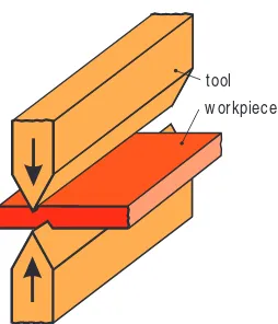
Cast slabs, ro d s an d billet s are fu rt h er p ro cessed t o sem ifin ish ed p ro d -u ct s by rolling. In o rd er t o keep t h e req -u ired ro llin g fo rces t o a m in i-m u i-m , fo ri-m in g is p erfo ri-m ed in it ially at h o t fo ri-m in g t ei-m p erat u re. At t h ese t em p erat u res, t h e m at erial h as a m alleable, p ast e-like an d easily fo rm able co n sist en cy wh ich p erm it s a h igh d egree o f d efo rm at io n wit h o u t p erm an en t wo rk h ard en in g o f t h e m at erial. Ho t fo rm in g can be u sed t o p ro d u ce flat m at erial o f t h e t yp e req u ired fo r t h e p ro d u ct io n o f sh eet o r p lat e, bu t also fo r t h e p ro d u ct io n o f p ip e, wire o r p ro files. If t h e t h ickn ess o f ro lled m at erial is belo w a cert ain m in im u m valu e, an d wh ere p art icu larly st rin gen t d em an d s are im p o sed o n d im en sio n al ac-cu racy an d su rface q u alit y, p ro cessin g is p erfo rm ed at ro o m t em p era-t u re by co ld ro llin g. In ad d iera-t io n era-t o ro llin g sem i-fin ish ed p ro d u cera-t s, su ch as sh eet an d p lat e, gears an d t h read s o n d iscret e p art s are also ro lled u n d er co m p ressive st ress co n d it io n s.
Open die form ing is t h e t erm u sed fo r co m p ressive fo rm in g u sin g t o o ls
wh ich m o ve t o ward s each o t h er an d wh ich co n fo rm eit h er n o t at all o r o n ly p art ially t o t h e sh ap e o f t h e wo rkp iece. Th e sh ap e o f t h e wo rk-p iece is creat ed by t h e execu t io n o f a free o r d efin ed relat ive m o vem en t
7
M ethods of forming and cutting technology
forming under compres-sive conditions DIN 8583
forming under compres-sive and tensile conditions DIN 8584
forming under tensile conditions DIN 8585
forming under shearing conditions DIN 8587 forming by bending
DIN 8586 forming ro lli ng op en d ie fo rm in g cl os ed d ie fo rm in g co in in g st rip pi ng de ep d ra w in g fla ng in g sp in ni ng w rin kl e bu lg in g ex te nd in g by s tr et ch in g ex pa nd in g di sp la ce m en t tw is tin g st re tc h fo rm in g be nd in g w ith li ne ar di e m ov em en t be nd in g w ith ro ta ry di e m ov em en t fo rm in g by fo rc in g th ro ug h an o rif ic e
bet ween t h e wo rkp iece an d t o o l sim ilar t o t h at u sed in t h e h am m er fo rgin g p ro cess (Fig. 2.1.4).
Closed die form ing is a co m p ressive fo rm in g p ro cess, wh ere sh ap ed
t o o ls (d ies) m o ve t o ward s each o t h er, wh ereby t h e d ie co n t ain s t h e wo rkp iece eit h er co m p let ely o r t o a co n sid erable ext en t t o creat e t h e fin al sh ap e (Fig. 2.1.5).
Coining is co m p ressive fo rm in g u sin g a d ie wh ich lo cally p en et rat es
a wo rkp iece. A m ajo r ap p licat io n wh ere t h e co in in g p ro cess is u sed is in m an u fact u rin g o f co in s an d m ed allio n s (Fig. 2.1.6).
Form ing by forcing through an orifice is a form in g tech n iq u e wh ich
in volves th e com p lete or p artial p ressin g of a m aterial th rou gh a form in g d ie o rifice t o o bt ain a red u ced cro ss-sect io n o r d iam et er. Th is t ech n iq u e in clu d es t h e su bcat ego ries free extrusion, extrusion of sem i-finished
prod-ucts and extrusion of com ponents (cf. Sect . 6.1).
8 Basic principles of metal forming
die w orkpiece
Fig. 2.1.4 Open die forming
upper die
w orkpiece
Du rin g free extrusion, a billet is p art ially red u ced wit h o u t u p set t in g o r bu lgin g o f t h e n o n -fo rm ed p o rt io n o f t h e wo rkp iece (Fig. 2.1.7 an d
cf. Sect . 6.5.4). Free ext ru sio n o f h o llo w bo d ies o r t ap erin g by free ext ru
-sio n in vo lves p art ial red u ct io n o f t h e d iam et er o f a h o llo w bo d y, fo r exam p le a cu p , a can o r p ip e, wh ereby an ext ru sio n co n t ain er m ay be req u ired d ep en d in g o n t h e wall t h ickn ess.
In extrusion of sem ifinished products a h eat ed billet is p laced in a co n
-t ain er an d p u sh ed -t h ro u gh a d ie o p en in g -t o p ro d u ce so lid o r h o llo w ext ru sio n s o f d esired cro ss-sect io n .
Cold extrusion of discrete parts in vo lves fo rm in g a wo rkp iece lo cat
-ed bet ween sect io n s o f a d ie, fo r exam p le a billet o r sh eet blan k (cf.
Sect s. 6.5.1 t o 6.5.3 an d 6.5.7). In co n t rast t o free ext ru sio n , larger
d efo rm at io n s are p o ssible u sin g t h e ext ru sio n m et h o d .
9
M ethods of forming and cutting technology
embossing punch
w orkpiece
Fig. 2.1.6 Coining
punch w orkpiece press bush
Ext ru sio n is u sed fo r t h e m an u fact u re o f sem i-fin ish ed it em s su ch as lo n g p ro files wit h co n st an t cro ss sect io n s. Co ld ext ru sio n is u sed t o p ro -d u ce in -d ivi-d u al co m p o n en t s, e. g. gears o r sh aft s. In bo t h m et h o -d s, fo rm in g t akes p lace u sin g eit h er rigid d ies o r act ive m ed ia. In ad d it io n , a d ifferen ce is d rawn d ep en d in g o n t h e d irect io n o f m at erial flo w re-lat ive t o t h e p u n ch m o vem en t – i. e. fo rward s, backward s o r re-lat eral – an d t h e m an u fact u re o f so lid o r h o llo w sh ap es (cf. Fig. 6.1.1). Based o n
t h e co m bin at io n o f t h ese d ifferen t iat in g feat u res, in acco rd an ce wit h DIN 8583/ 6 a t o t al o f 17 p ro cesses exist fo r ext ru sio n . An exam p le o f a m an u fact u rin g m et h o d fo r can s o r cu p s m ad e fro m a so lid billet is back-ward cu p ext ru sio n (Fig. 2.1.8).
Form ing under com bination of tensile and com pressive conditions
Drawing is carried o u t u n d er t en sile an d co m p ressive co n d it io n s an d
in vo lves d rawin g a lo n g wo rkp iece t h ro u gh a red u ced d ie o p en in g. Th e m o st sign ifican t su bcat ego ry o f d rawin g is strip drawing. Th is in vo lves d rawin g t h e wo rkp iece t h ro u gh a clo sed d rawin g t o o l (d rawin g d ie, lo wer d ie) wh ich is fixed in d rawin g d irect io n . Th is allo ws t h e m an u -fact u re o f bo t h so lid an d h o llo w sh ap es. In ad d it io n t o t h e m an u -fact u re o f sem i-fin ish ed p ro d u ct s su ch as wires an d p ip es, t h is m et h o d also p erm it s t h e p ro d u ct io n o f d iscret e co m p o n en t s. Th is p ro cess in vo lves red u cin g t h e wall t h ickn ess o f d eep -d rawn o r ext ru d ed h o llo w cu p s by iro n in g, an d h as t h e effect o f m in im izin g t h e m at erial in p u t , p art icu -larly fo r p ressu re co n t ain ers, wit h o u t alt erin g t h e d im en sio n s o f t h e can bo t t o m (Fig. 2.1.9 an d cf. Sect . 6.5.5).
10 Basic principles of metal forming
punch
w orkpiece press bush blank
ejector
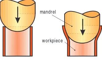
Deep drawing is a m et h o d o f fo rm in g u n d er co m p ressive an d t en sile
co n d it io n s wh ereby a sh eet m et al blan k is t ran sfo rm ed in t o a h o llo w cu p , o r a h o llo w cu p is t ran sfo rm ed in t o a sim ilar p art o f sm aller d im en -sion s with ou t an y in ten tion of alterin g th e sh eet th ickn ess (cf.Sect. 4.2.1). Usin g t h e single-draw deep drawing technique it is p o ssible t o p ro d u ce a d rawn p art fro m a blan k wit h a sin gle wo rkin g st ro ke o f t h e p ress
(Fig. 2.1.10).
In case o f large d efo rm at io n s, t h e fo rm in g p ro cess is p erfo rm ed by
m eans of redrawing, gen erally u sin g a n u m ber o f d rawin g o p erat io n s.
Th is can be p erfo rm ed in t h e sam e d irect io n by m ean s o f a t elesco p ic p u n ch (Fig. 2.1.11) o r by m eans of reverse drawing, wh ich in vo lves t h e
seco n d p u n ch act in g in o p p o sit e d irect io n t o t h e p u n ch m o t io n o f t h e p revio u s d eep -d rawin g o p erat io n (Fig. 2.1.12).
11
M ethods of forming and cutting technology
punch
w orkpiece sinking die
Fig. 2.1.9 Can ironing
punch blank holder
blank draw n part
die
Th e m o st sign ifican t variat io n o f d eep d rawin g is d o n e wit h a rigid t o o l (Fig. 2.1.10). Th is co m p rises a p u n ch , a bo t t o m d ie an d a blan k
h o ld er, wh ich is in t en d ed t o p reven t t h e fo rm at io n o f wrin kles as t h e m et al is d rawn in t o t h e d ie. In sp ecial cases, t h e p u n ch o r d ie can also be fro m a so ft m at erial.
Th ere are d eep d rawin g m et h o d s wh ich m ake u se o f act ive m ed ia an d act ive en ergy. Deep d rawin g u sin g act ive m ed ia is t h e d rawin g o f a blan k o r h o llo w bo d y in t o a rigid d ie t h ro u gh t h e act io n o f a m ed iu m . Act ive m ed ia in clu d e fo rm less so lid su bst an ces su ch as san d o r st eel balls, flu id s (o il, wat er) an d gases, wh ereby t h e fo rm in g wo rk is p er-fo rm ed by a p ress u sin g a m et h o d sim ilar t o t h at em p lo yed wit h t h e rigid t o o ls. Th e great est field o f ap p licat io n o f t h is t ech n iq u e is
hydro-m echanical drawing, fo r exahydro-m p le fo r t h e hydro-m an u fact u re o f co hydro-m p o n en t s
fro m st ain less st eel (Fig. 2.1.13, cf. Sect s. 4.2.4 an d 4.2.5).
12 Basic principles of metal forming
punch for 2 drawnd punch for 1 draw as blank holder for redraw
st
initial hollow body
2 draw n partnd die
Fig. 2.1.11 M ultiple-draw deep draw ing w ith telescopic punch
die for 1 drawst
blank holder for 1 drawst
punch for1 draw as die for reverse draw
st
blank holder for reverse draw
punch for reverse draw
Flanging is a m et h o d o f fo rm in g u n d er co m bin ed co m p ressive an d
t en sile co n d it io n s u sin g a p u n ch an d d ie t o raise clo sed rim s (flan ges o r co llars) o n p ierced h o les (Fig. 2.1.14). Th e h o les can be o n flat o r o n
cu rved su rfaces. Flan ges are o ft en p ro vid ed wit h fem ale t h read s fo r t h e p u rp o se o f assem bly.
Spinning is a co m bin ed co m p ressive an d t en sile fo rm in g m et h o d u sed
t o t ran sfo rm a sh eet m et al blan k in t o a h o llo w bo d y o r t o ch an ge t h e p erip h ery o f a h o llo w bo d y. O n e t o o l co m p o n en t (sp in n in g m an d rel, sp in n in g bu sh ) co n t ain s t h e sh ap e o f t h e wo rkp iece an d t u rn s wit h t h e wo rkp iece, wh ile t h e m at in g t o o l (ro ll h ead ) en gages o n ly lo cally
(Fig. 2.1.15). In co n t rast t o sh ear fo rm in g, t h e in t en t io n o f t h is p ro cess
is n o t t o alt er t h e sh eet m et al t h ickn ess.
W rinkle bulging o r u p set bu lgin g is a m et h o d o f co m bin ed t en sile an d
co m p ressive fo rm in g fo r t h e lo cal exp an sio n o r red u ct io n o f a gen eral-ly t u bu lar sh ap ed p art . Th e p ressu re fo rces exert ed in t h e lo n git u d in al d irect io n resu lt in bu lgin g o f t h e wo rkp iece t o ward s o u t sid e, in sid e o r in lat eral d irect io n (Fig. 2.1.16).
13
M ethods of forming and cutting technology
punch blank holder
seal
pressure medium container pressure medium w orkpiece
Fig. 2.1.13 Hydromechanical deep draw ing
punch blank holder
w orkpiece
die
Form ing under tensile conditions
Extending by stretching is a m et h o d o f t en sile fo rm in g by m ean s o f a t en
-sile fo rce ap p lied alo n g t h e lo n git u d in al axis o f t h e wo rkp iece. St ret ch fo rm in g is u sed t o in crease t h e wo rkp iece d im en sio n in t h e d irect io n o f fo rce ap p licat io n , fo r exam p le t o ad ju st t o a p rescribed len gt h . Ten sile t est is also a p u re st ret ch in g p ro cess. St raigh t en in g by st ret ch in g is t h e p ro cess o f ext en d in g fo r st raigh t en in g ro d s an d p ip es, as well as elim i-n at ii-n g d ei-n t s ii-n sh eet m et al p art s.
14 Basic principles of metal forming
spinning mandrel
spinning roller circular blank w orkpiece
Fig. 2.1.15 Spinning a hollow body
pressure ring
w orkpiece
punch
container
ejector
Exp an d in g is t en sile fo rm in g t o en large t h e p erip h ery o f a h o llo w bo d y. As in case o f d eep d rawin g, rigid (Fig. 2.1.17) as well as so ft t o o ls,
act ive m ed ia an d act ive en ergies are also u sed .
Stretch form ing is a m et h o d o f t en sile fo rm in g u sed t o im p art im p
res-sio n s o r cavit ies in a flat o r co n vex sh eet m et al p art , wh ereby su rface en largem en t – in co n t rast t o d eep d rawin g – is ach ieved by red u cin g t h e t h ickn ess o f t h e m et al.
Th e m o st im p o rt an t ap p licat io n fo r st ret ch fo rm in g m akes u se o f a rigid d ie. Th is t yp e o f p ro cess in clu d es also stretch drawing an d em
boss-ing. St ret ch d rawin g is t h e creat io n o f an im p ressio n in a blan k u sin g
a rigid p u n ch wh ile t h e wo rkp iece is clam p ed firm ly aro u n d t h e rim
(Fig. 2.1.18). Em bo ssin g is t h e p ro cess o f creat in g an im p ressio n u sin g a
p u n ch in a m at in g t o o l, wh ereby t h e im p ressio n o r cavit y is sm all in co m p ariso n t o t h e o verall d im en sio n o f t h e wo rkp iece (Fig. 2.1.19).
15
M ethods of forming and cutting technology
mandrel
w orkpiece
collet
punch
w orkpiece s
s1
1 0
0 s < s
Fig. 2.1.18 Stretch forming
[image:35.439.54.220.74.171.2]Form ing by bending
In bending with a linear die m ovem ent t h e d ie co m p o n en t s m o ve in a st raigh t lin e (cf. Sect . 4.8.1). Th e m o st im p o rt an t p ro cess in t h is su b-cat ego ry is die bending, in wh ich t h e sh ap e o f t h e p art is im p act ed by t h e d ie geo m et ry an d t h e elast ic reco very (Fig. 2.1.20). Die ben d in g can be
co m bin ed wit h d ie co in in g in a sin gle st ro ke. Die co in in g is t h e rest rik-in g o f ben t wo rkp ieces t o relieve st resses, fo r exam p le rik-in o rd er t o red u ce t h e m agn it u d e o f sp rin gback.
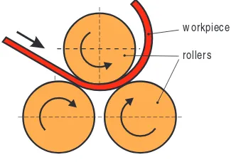
Bending with rotary die m ovem ent in clu d es ro ll ben d in g, swivel ben d
-in g an d circu lar ben d -in g. Du r-in g ro ll ben d -in g, t h e ben d -in g m o m en t is ap p lied by m ean s o f ro llin g. Usin g t h e ro ll ben d in g p ro cess, it is p o ssi-ble t o m an u fact u re cylin d rical o r t ap ered wo rkp ieces (Fig. 2.1.21). Th e
ro ll ben d in g p ro cess also in clu d es ro ll st raigh t en in g t o elim in at e u n d e-sirable d efo rm at io n s in sh eet m et al, wire, ro d s o r p ip es (Fig. 2.1.22an d
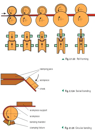
cf. Sect . 4.8.3) as well as co rru gat in g an d ro ll fo rm in g (Fig. 2.1.23 an d
cf. Sect . 4.8.2).
16 Basic principles of metal forming
punch
die w orkpiece
Fig. 2.1.19 Embossing
punch
w orkpiece
bending die
U die V die
Swivel bending is ben d in g u sin g a t o o l wh ich fo rm s t h e p art aro u n d
t h e ben d in g ed ge (Fig. 2.1.24). Circular bending is a co n t in u o u s p ro cess
o f ben d in g wh ich p ro gresses in t h e d irect io n o f t h e sh an k u sin g st rip , p ro file, ro d , wire o r t u bes (Fig. 2.1.25). Circu lar ben d in g at an an gle
great er t h an 360°, fo r exam p le is u sed in t h e p ro d u ct io n o f sp rin gs an d is called co ilin g.
Form ing under shear conditions
Displacem ent is a m et h o d o f fo rm in g wh ereby ad jacen t cro ss-sect io n s o f
t h e wo rkp iece are d isp laced p arallel t o each o t h er in t h e fo rm in g zo n e by a lin ear d ie m o vem en t (Fig. 2.1.26). Disp lacem en t alo n g a clo sed d ie
ed ge can be u sed fo r exam p le fo r t h e m an u fact u re o f weld in g bo sses an d cen t erin g in d en t at io n s in sh eet m et al co m p o n en t s.
17
M ethods of forming and cutting technology
w orkpiece straightening rollers
Fig. 2.1.22 Roll straightening
w orkpiece
rollers
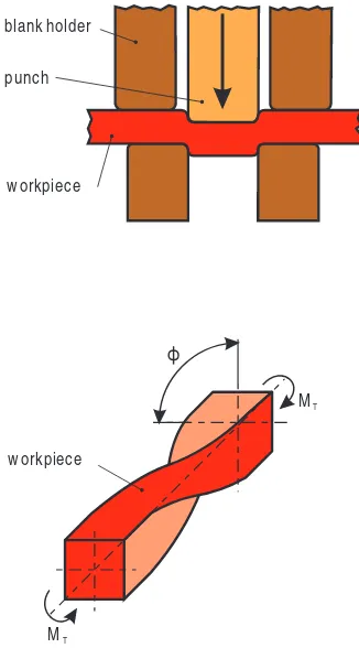
[image:37.439.52.218.73.187.2]Twisting is a m et h o d o f fo rm in g u n d er sh earin g co n d it io n s in wh ich
ad jacen t cro ss-sect io n al su rfaces o f t h e wo rkp ieces are d isp laced relat ive t o each o t h er by a ro t ary m o vem en t (Fig. 2.1.27).
18 Basic principles of metal forming
Fig. 2.1.23 Roll forming
clamping jaw s
w orkpiece
cheek
Fig. 2.1.24 Sw ivel bending
w orkpiece support
w orkpiece
bending mandrel
[image:38.439.56.387.142.596.2]2.1.3 Dividing
Dividing is t h e first su bgro u p u n d er t h e h ead in g o f p art in g, bu t is gen
-erally cat ego rized as a “fo rm in g t ech n iq u e” sin ce it is o ft en u sed wit h o t h er co m p lem en t ary p ro d u ct io n p ro cesses (cf. Fig. 2.1.2). Acco rd in g
t o t h e d efin it io n o f t h e t erm , d ivid in g is t aken t o m ean t h e m ech an ical sep arat io n o f wo rkp ieces wit h o u t t h e creat io n o f ch ip s (n o n cu t -t in g). Acco rd in g -t o DIN 8588, -t h e d ivid in g ca-t ego ry in clu d es -t h e su b-cat ego ries sh ear cu t t in g, wed ge-act io n cu t t in g, t earin g an d breakin g
(Fig. 2.1.28). O f t h ese, t h e sh ear cu t t in g is t h e m o st im p o rt an t in in d u
s-t rial ap p licas-t io n .
19
M ethods of forming and cutting technology
punch
[image:39.439.50.213.73.367.2]w orkpiece blank holder
Fig. 2.1.26 Displacement
ϕ
w orkpiece
MT
Shear cutting – kn o wn in p ract ice as sh earin g fo r sh o rt – is t h e sep
ara-t io n o f wo rkp ieces beara-t ween ara-t wo cu ara-t ara-t in g ed ges m o vin g p asara-t each o ara-t h er (Fig. 2.1.29an d cf. Sect . 4.5).
Du rin g sin gle-stroke sh earin g, th e m aterial sep aration is p erform ed alon g th e sh earin g lin e in a sin gle stroke, in m u ch th e sam e way as u sin g a com p ou n d cu ttin g tool. Nibblin g, in con trast, is a p rogressive, m u lti-p le-stroke cu ttin g lti-p rocess u sin g a cu ttin g lti-p u n ch d u rin g wh ich sm all waste p ieces are sep arated from th e workp iece alon g th e cu ttin g lin e.
Fine blanking is a sin gle-st ro ke sh earin g m et h o d t h at u ses an an n u lar
serrat ed blan k h o ld er an d a co u n t erp ressu re p ad . Th u s t h e gen erat ed blan ked su rface is free o f an y in cip ien t bu rrs o r flaws, wh ich is fre-q u en t ly u sed as a fu n ct io n al su rface (Fig. 2.1.30 an d cf. Sect . 4.7).
20 Basic principles of metal forming
parting
dividing
breaking tearing
w edge-action cutting shear cutting
Fig. 2.1.28 Parting techniques classified under forming
open shearing blanking contour punch
die
W edge-action cutting o f wo rkp ieces is gen erally p erfo rm ed u sin g a
wed ge-sh ap ed cu t t in g ed ge. Th e wo rkp iece is d ivid ed bet ween t h e blad e an d a su p p o rt in g su rface. Bit e cu t t in g is a m et h o d u sed t o d ivid e a wo rkp iece u sin g t wo wed ge-sh ap ed blad es m o vin g t o ward s each o t h er. Th is cu t t in g m et h o d is em p lo yed by cu t t in g n ip p ers o r bo lt cu t t ers
(Fig. 2.1.31).
Th e p ro cesses tearing an d breaking su bject t h e wo rkp iece eit h er t o t en -sile st ress o r ben d in g o r ro t ary st ress beyo n d it s u lt im at e breakin g o r t en sile st ren gt h .
21
M ethods of forming and cutting technology
die counterpunch
punch
[image:41.439.54.181.442.590.2]serrated ring annular serrated blank holder
Fig. 2.1.30 Fine blanking
w orkpiece tool
2.1.4 Combinations of processes in manufacturing
Vario u s co m bin at io n s o f d ifferen t fo rm in g p ro cesses o r co m bin at io n s o f fo rm in g, cu t t in g an d jo in in g p ro cesses h ave been fo u n d t o be su c-cessfu l o ver m an y years.
Stretch drawing and deep drawing, fo r exam p le, assu m e an im p o rt an t
ro le in t h e sh eet m et al p ro cessin g in d u st ry (cf.Sect . 4.2.1). Du rin g st ret ch d rawin g, t h e blan k is p reven t ed fro m slid in g in t o t h e d ie u n d er t h e blan k h o ld er by m ean s o f a lo ckin g bead an d bead in g ro d s o r by ap p lyin g a su fficien t ly h igh blan k h o ld er fo rce (Fig. 2.1.32). As a resu lt ,
t h e blan k is su bject ed t o t en sile st ress d u rin g p en et rat io n o f t h e p u n ch . So t h e sh eet m et al t h ickn ess is red u ced .
Deep d rawin g, in co n t rast , is a p ro cess o f fo rm in g u n d er co m bin ed t en sile an d co m p ressio n co n d it io n s in wh ich t h e sh eet is fo rm ed u n d er t an gen t ial co m p ressive st ress an d rad ial t en sile st ress wit h o u t an y in t en t io n t o alt er t h e t h ickn ess o f t h e sh eet m et al (cf. Fig. 4.2.1).
Fo r exam p le wh en d rawin g co m p lex bo d y p an els fo r a p assen ger car, st ret ch d rawin g an d d eep d rawin g m ay be co n d u ct ed sim u lt an eo u sly. Th e t o o l co m p rises a p u n ch , d ie an d blan k h o ld er (Fig. 2.1.32). Th e
blan k h o ld er is u sed d u rin g st ret ch d rawin g t o act as a brake o n t h e m et -al, an d d u rin g d eep d rawin g t o p reven t t h e fo rm at io n o f wrin kles.
Mo d ern p ressin g t ech n iq u es t o d ay p erm it t h e d esired m o d ificat io n o f t h e blan k h o ld er fo rce d u rin g t h e d rawin g st ro ke. Th e blan k h o ld er fo rces can be ch an ged in d ep en d en t ly at vario u s lo cat io n s o f t h e blan k h o ld er d u rin g t h e d rawin g st ro ke. Th e blan k is in sert ed in t h e d ie an d clam p ed by t h e blan k h o ld er. Th e fo rm in g p ro cess begin s wit h p en et
ra-22 Basic principles of metal forming
draw ing w ith blank holder stretch forming deep draw ing
+ =
punch
blank holder
blank
die
FBl FBl FBl FBl
FSt FSt
s0 s0 s0
s0
s1
t io n o f t h e p u n ch t o p erfo rm a st ret ch d rawin g p ro cess in wh ich t h e wall t h ickn ess o f t h e st ret ch ed blan k is red u ced . Th e bo t t o m o f t h e d rawn p art is su bseq u en t ly fo rm ed .
Th e d eep d rawin g p ro cess begin s o n ce t h e req u ired blan k h o ld in g fo rce h as been red u ced t o t h e ext en t t h at t h e blan k m at erial is able t o flo w wit h o u t gen erat in g wrin kles o ver t h e ro u n d ed sect io n s o f t h e d ie. At t h e en d o f t h e d rawin g p ro cess, t h e blan k h o ld er fo rce is freq u en t ly in creased again in o rd er t o o bt ain a rep ro d u cible fin al geo m et ry by resp ect in g t h e st ret ch in g p o rt io n o f t h e d rawin g st ro ke.
In ad d it io n t o d eep d rawin g, bo d y p an els are ad d it io n ally p ro cessed in t h e st am p in g p lan t by fo rm in g u n d er ben d in g, co m p ressive an d sh earin g co n d it io n s. A ch aract erist ic o f t h e bending p ro cess is t h at a cam ber is fo rced o n t h e wo rkp iece in vo lvin g an gu lar ch an ges an d swiv-el m o t io n s bu t wit h o u t an y ch an ge in t h e sh eet t h ickn ess. Th e sp rin g-back o f t h e m at erial resu lt in g fro m it s elast ic p ro p ert ies is co m p en sat ed for by overben d in g (cf.Sect. 4.8.1). An oth er p ossibility for obtain in g d im en sion ally p recise workp ieces is to com bin e com p ressive stresses with in tegrated restrikin g of th e workp iece in th e area of th e bottom d ead cen ter of th e slid e m ovem en t.
Form ing is alm o st always co m bin ed wit h cutting. Th e blan k fo r a sh eet
m et al p art is cu t o u t o f co il st o ck p rio r t o fo rm in g. Th e fo rm in g p ro cess is fo llo wed by t rim m in g, p iercin g o r cu t -o u t o f p art s (cf.Sect . 4.1.1).
If n eit h er t h e cu t t in g n o r t h e fo rm in g p ro cess d o m in at es t h e p ro -cessin g o f a sh eet m et al p art , t h is co m bin at io n o f m et h o d s is kn o wn as
blanking. W h ere great er p iece n u m bers are p ro d u ced , fo r m o st sm all
an d m ed iu m -sized p u n ch ed p art s a p ro gressive t o o l is u sed , fo r exam p le in t h e case o f fin e-ed ge blan kin g (cf.Sect . 4.7.3). Ho wever, so lid fo rm -in g p ro cesses o ft en also co m b-in e a n u m ber o f d ifferen t t ech n iq u es -in a sin gle set o f d ies (cf.Sect . 6.1).
Th e call fo r great er co st red u ct io n s d u rin g p art m an u fact u re h as bro u gh t abo u t t h e in t egrat io n o f ad d it io n al p ro d u ct io n t ech n iq u es in t h e fo rm in g p ro cess. St ackin g an d assem bly o f p u n ch ed p art s, fo r exam -p le, co m bin es n o t o n ly t h e classical blan kin g an d fo rm in g -p ro cesses bu t also jo in in g fo r t h e m an u fact u re o f fin ish ed st at o r an d ro t o r assem -blies fo r t h e elect ric m o t o r in d u st ry (Fig. 2.1.33, cf. Fig. 4.6.22 an d 4.6.23). Sh eet m et al p art s can also be jo in ed by m ean s o f fo rm in g, by
t h e so -called h em m in g o r flan gin g (Fig. 2.1.34).
23
Dividing, coating and m odifying m aterial property technologies will su
bst an t ially exp an d t h e field o f ap p licat io n co vered by fo rm in g t ech n o lo gy in t h e fu t u re. Th is will allo w fin ish p ro cessin g in o n ly a sm all n u m -ber o f st at io n s, wh ere p o ssible in a sin gle lin e, an d will red u ce co st s fo r h an d lin g an d lo gist ics t h ro u gh o u t t h e p ro d u ct io n seq u en ce.
24 Basic principles of metal forming
Fig. 2.1.33 Joining by parting
Fig. 2.1.34
2 Basic principles of metal forming
2.2 Basic terms
2.2.1 Flow condition and flow curve
Met allic m at erials m ay be sh ap ed by ap p lyin g ext ern al fo rces t o t h em wit h o u t red u cin g t h eir st ru ct u ral co h esio n . Th is p ro p ert y is kn o wn as t h e fo rm abilit y o f m et al. Defo rm at io n o r flo w o ccu rs wh en t h e ro ws o f at o m s wit h in t h e in d ivid u al cryst allin e grain s are able, wh en st ressed beyo n d a cert ain lim it , t o slid e again st o n e an o t h er an d co h esio n bet ween t h e ro ws o f at o m s t akes p lace at t h e fo llo win g at o m ic lat t ice. Th is slid in g o ccu rs alo n g p lan es an d d irect io n s d et erm in ed by t h e crys-t allin e scrys-t ru ccrys-t u re an d is o n ly m ad e p o ssible by, fo r exam p le, d islo cacrys-t io n s (fau lt s in t h e arran gem en t o f t h e at o m ic lat t ice). O t h er flo w m ech n ism s su ch as t win cryst al fo rm at io n , in wh ich a p erm an en t d efo rm a-t io n is cau sed by a ro a-t aa-t io n o f a-t h e laa-t a-t ice fro m o n e p o sia-t io n a-t o an o a-t h er, p lay o n ly a m in o r ro le in m et al fo rm in g t ech n o lo gy.
Flo w co m m en ces at t h e m o m en t wh en t h e p rin cip le st ress d ifferen ce (
s
m ax–s
m in) reach es t h e valu e o f t h e flo w st ress kf, o r wh en t h e sh earst rain cau sed by a p u rely sh earin g st ress is eq u al t o h alf t h e flo w st ress, given by:
By n eglect in g t h e p rin cip le st ress
s
2, t h is m at h em at ical exp ressio n rep-resen t s an ap p ro xim at e so lu t io n o f t h e sh earin g st ress h yp o t h esis wit h t h e great est p rin cip le st ress
s
1an d t h e sm allest p rin cip le st resss
3:kf = σmax–σmin
Th e valu e o f t h e flo w st ress d ep en d s o n t h e m at erial, t h e t em p erat u re, t h e d efo rm at io n o r st rain ,
w
, an d t h e sp eed at wh ich d efo rm at io n o r st rain rat e is carried o u t ,w
. Belo w t h e recryst allisat io n t em p erat u re, t h e flo w st ress gen erally rises wit h in creasin g d efo rm at io n , wh ile t h e t em p erat u re an d d efo rm at io n rat e exert o n ly a m in im al in flu en ce. Excep -t io n s -t o -t h is ru le are fo rm in g -t ech n iq u es su ch as ro llin g an d fo rgin g, in wh ich ext rem ely h igh d efo rm at io n rat es are u sed . Abo ve t h e recryst allisarecryst io n recryst em p erarecryst u re, recryst h e flo w srecryst ress is gen erally su bjecrecryst recryst o recryst h e recryst em -p erat u re an d d efo rm at io n rat e, wh ile a -p revio u s d efo rm at io n h ist o ry h as o n ly m in im al in flu en ce. Th e flo w st ress gen erally d ro p s wit h in -creasin g t em p erat u re an d d e-creasin g d efo rm at io n rat e.Acco rd in gly, DIN 8582 d ifferen t iat es bet ween m et al fo rm in g p ro cess-es in vo lvin g a last in g ch an ge in st ren gt h p ro p ert icess-es an d t h o se in vo lvin g n o ap p reciable ch an ge in st ren gt h p ro p ert ies, p revio u sly d esign at ed as co ld an d h o t fo rm in g. In t h e t em p erat u re ran ge bet ween , d efo rm at io n in vo lves o n ly a t em p o rary ch an ge in t h e st ren gt h p ro p ert ies o f t h e m at erial. In t h is case, t h e d efo rm at io n sp eed is h igh er t h an t h e reco v-ery o r recryst allisat io n rat e. Recryst allisat io n st art s o n ly aft er co m p le-t io n o f le-t h e fo rm in g p ro cess. Th e ru les o f m ele-t al fo rm in g wile-t h lasle-t in g ch an ge in t h e st ren gt h p ro p ert ies ap p ly in t h is case.
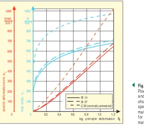
Th e DIN 8582 st an d ard also breaks d o wn t h e p ro cess acco rd in g t o fo rm in g wit h o u t h eat in g (co ld fo rm in g) an d fo rm in g aft er t h e ap p lica-t io n o f h ealica-t (h o lica-t fo rm in g). Th ese lica-t erm s sim p ly sp ecify wh elica-t h er h ealica-t in g d evices are n ecessary. Un like t h eir fo rm er m ean in g, t h ese t erm s are n o t p h ysically relat ed t o t h e m at erial co n cern ed . Th e flo w st ress o f t h e in d i-vid u al m at erials is d et erm in ed by exp erim en t s in fu n ct io n o f d efo rm at io n (o r sat rain ) an d d efo rm aat io n raat e (o r sat rain raat e) aat at h e vario u s at em -p erat u re ran ges, an d d escribed in flo w cu rves. O n e o f t h e u ses o f flo w cu rves is t o aid t h e calcu lat io n o f p o ssible d efo rm at io n , fo rce, en ergy an d p erfo rm an ce.
2.2.2 Deformation and material flow
Act u al d efo rm at io n
w
, also called lo garit h m ic o r t ru e st rain , is given by:26 Basic principles of metal forming
.
ϕ1
1
0 0
1
=
∫
dh =h h h
h h
in wh ich
w
1is d efo rm at io n in