Journal of Physics: Conference Series
PAPER • OPEN ACCESS
A numerical study on combustion process in a
small compression ignition engine run dual-fuel
mode (diesel-biogas)
To cite this article: H Ambarita et al 2017 J. Phys.: Conf. Ser.801 012095
View the article online for updates and enhancements.
Related content
Performance and Emissions of a Small Compression Ignition Engine Run on Dual-fuel Mode (Diesel-Raw biogas)
H Ambarita, E P Sinulingga, M KM Nasution et al.
-Effect of engine load and biogas flow rate to the performance of a compression ignition engine fueled with a mix of DME and diesel
Effect of engine load and biogas flow rate to the performance of a compression is a potential solution to meet Indonesia emission target
Himsar Ambarita
A numerical study on combustion process in a small
compression ignition engine run dual-fuel mode (diesel-biogas)
H Ambarita, T.I Widodo, and D.M Nasution
Sustainable Energy Research Centre, Faculty of Engineering University of Sumatera Utara, Jl. Almamater Kampus USU Medan 20155, Indonesia
Email: [email protected]
Abstract. In order to reduce the consumption of fossil fuel of a compression ignition (CI) engines which is usually used in transportation and heavy machineries, it can be operated in dual-fuel mode (diesel-biogas). However, the literature reviews show that the thermal efficiency is lower due to incomplete combustion process. In order to increase the efficiency, the combustion process in the combustion chamber need to be explored. Here, a commercial CFD code is used to explore the combustion process of a small CI engine run on dual fuel mode (diesel-biogas). The turbulent governing equations are solved based on finite volume method. A simulation of compression and expansions strokes at an engine speed and load of 1000 rpm and 2500W, respectively has been carried out. The pressure and temperature distributions and streamlines are plotted. The simulation results show that at engine power of 732.27 Watt the thermal efficiency is 9.05%. The experiment and simulation results show a good agreement. The method developed in this study can be used to investigate the combustion process of CI engine run on dual-fuel mode.
1. Introduction
Green Houses Gases (GHGs) emissions can cause global warming and it can make the earth in dangerous. The main sources of GHGs emissions are deforestation and burning fossil fuel. Indonesia is one of the main GHGs emitter in the world. The Government of Indonesia (GoI) has released its target on reduction GHGs emissions [1]. The burning of fossil fuel includes activities that using engines to produce power. As a note, the main consumption of fossil fuel is diesel which is used in Compression Ignition (CI) engines. Thus, reducing diesel oil consumption will reduce GHGs emissions significantly. Due to thermodynamic principle of combustion engines and the Carnot cycle limit, the emission target can only be achieved with fuel change or blending with biofuel. Here biogas is promoted to replace the biodiesel. Biogas is produced from anaerobic biodegradation of organic material. It consists of methane typically ranges from 40 - 70% and its low heating value is between 15 and 30 MJ/Nm3. There are two
methodologies that can be used to run CI engines with biogas. The first methodology is converting the CI engine into pure biogas engine and the second one is dual-fuel mode (diesel-biogas). In the CI engine with dual-fuel mode, after compression of the charge comprised of biogas and air, a small amount of diesel, called the pilot is injected. This injected pilot fuel gets self-ignited and then becomes the ignition source for the inducted biogas. The main advantage of dual-fuel CI engines is that they can work with a wide variety of gaseous fuels without engine modifications [2]. This study focuses on CI engine run on dual-fuel mode.
Several studies on CI engine run on dual-fuel mode have been found in literature. Bedoya et al [3] reported a study on the effect of mixing system and pilot fuel quality on diesel-biogas dual-fuel engine performance. Cacua et al [4] studied experimentally the effects of oxygen enriched air on the operation and performance of a diesel-biogas dual-fuel engine. Tippayong et al [5] carried out a study on electricity production for on-farm using a small CI dual-fuel diesel-biogas. Their main objective was to evaluate the effect of long-term operation on performance and wear of the dual-fuel engine. The CI engine was tested for 2000 hours of operation. Makareviciene et al [6] explored the impacts of CH4 compositions
in a big CI four stoke and four-cylinders engine when operated under dual-fuel biogas-diesel mode. The impact of exhaust gas recirculation (EGR) was also explored. Tonkunya and Wongwuttanasatian [7] reported a study on the utilization of biogas-diesel mixture as fuel in a fertilizer pelletizing machine for reduction of GHG emission in small farms. The results showed that by using biogas as dual-fuel mode in the CI engine, a reduction in diesel fuel of 63% was achieved. This result was equivalent to 13 ton CO2eq/year/farm in Thailand case. Nathan et al [8] performed an experimental study on the
biogas-biodiesel HCCI mode of engine operation. The objective was to investigate the potential of the HCCI concept to utilize biogas effectively. Recently, Ambarita et al [9] reported an experimental study on the performance of small CI engine run on raw biogas. Mainly the studies of CI engine run on dual-fuel uses experimental method and only several studies use numerical method [10,11]. Yousefi et al [11] used CFD method to investigate effect of premixed fuel on the performance and emissions of dual-fuel pilot diesel engine.
The above literatures show that study on CI engine run on dual-fuel mode in order to decrease the fossil fuel has come under scrutiny. However, when it is operated on dual-fuel (diesel-biogas), thermal efficiency is relatively lower. In order to improve the thermal efficiency, several modifications have been proposed by researchers. Numerical simulation can be used to explore the combustion process on diesel engine run on dual-fuel mode. The better understanding of the combustion process in the CI engine run on dual-fuel mode is needed to improve the thermal efficiency. In this study, a numerical method is developed to investigate the combustion process in the CI engine run on dual-fuel mode. The main objective is to provide an alternative method in exploring the combustion process in the CI engine run on dual-fuel mode. The results are expected to supply the necessary information on development of alternative solutions for increasing thermal efficiency of CI engine run on dual-fuel mode.
2. Method
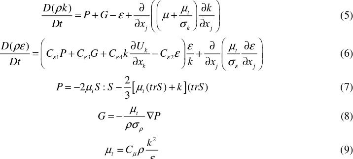
In the simulation, the governing equations are solved numerically. In order to simulate the combustion process in the chamber a set of governing equations have been developed. The governing equations consist of Navier-Stokes and energy equations, turbulent equations, and chemical kinetics equations [12]. The Navier-Stokes and energy equations are explained below.
(
U)
0density, pressure, viscosity, specific enthalpy, conductivity, mass concentration of species, and diffusivity coefficient.
2
In order to simulate the turbulent flow in the combustion chamber, the two-equations of k-epsilon model is employed. The governing equations and the source terms are calculated using the following equations:
Where k[m/s2], ε[kg/ms3], and r[kg/s] are turbulent kinetic energy, weighted turbulence dissipation
rate, and species source production. To determine the necessary sources terms in the momentum and energy equations in each time step, the following general form of reaction is used.
, ,
The reaction rate (RR) will be calculated using
[
]
[ ]
,[ ]
,In this equation, K is the reaction rate which is calculated using Arrhenius equation formulated below.
exp
In each time step production or destruction rate (ωi) of each species is determined by using:
(
, ,)
All of those governings equations are converted into linier equations by employing finite volume method. The system of liner equations for all fields are coupled using SIMPLE algorith. The commercial code of ANSYS FLUENT is used to carry out the simulation. In the simulation the used biogas has methane percentage of volume is 60%. In this study a CI engine which is originally used in a small tractor for agricultural will be tested in the experimental apparatus. The specifications of the CI engine are presented in Table 1.
Table 1. Specification of the CI engine
No Parameter Value
1 Commercial name/model Tiger Diesel Engine R175 AN
2 Number of cylinder/stroke Single-cylinder/4 strokes and Horizontal 4 Bore × Stroke 75 mm × 80 mm
5 Maximum output 4.86 kW
In order to validate the numerical results, experiments are performed. An experimental apparatus has been designed and developed. It consists of a unit of CI engine, generator, series of lamps, biogas tank, gas mixer, and measurements apparatus. In single fuel mode (pure diesel oil only) the CI engine will be tested without modification. In dual-fuel mode, a gas mixer has been designed and developed in order to mix the fresh air with biogas. The mixture of the fresh air and biogas will be injected into the CI engine. To simulate the load, the CI engine will be coupled with a single phase synchronous generator using pulley.
3. Results and Discussions
3.1. The model
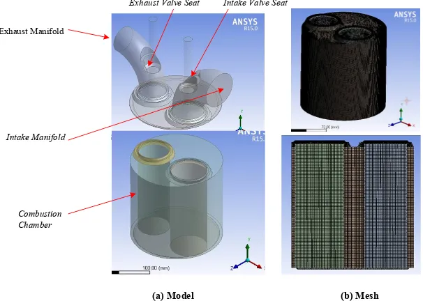
In this simulation, three-dimensional model of the combustion chamber was developed using CAD software. The developed CAD model and mesh of the combustion chamber are shown in Figure 1. The model is divided into several sub-models in order to make the analysis.
Figure 1. The developed CAD model (a) and mesh of the combustion chamber
3.2. Numerical Validation
In order to validate the numerical method, a numerical validation has been carried out by comparing the experimental results and numerical one. The comparisons were made for engine speed of 1000 rpm and biogas injection rate of 2L/minute. The engine was loaded with a load of 2500 Watt. The output power, torque and thermal efficiency are compared as shown in Table 2. The table shows that the experimental and numerical results do agree well. Based on these validation, the numerical method will be used to simulate the combustion process in combustion chamber.
Table 2. Numerical and Experimental results at load 2500 W and 1000 rpm Parameter Experimental result Numerical result Difference [%] Power [W] 736.44 732.27 0.55 Torque [Nm] 7.04 6.996 0.65 Efficiency [%] 9.10 9.05 0.54
4
3.3. Pressure distribution
Pressure distributions inside the combustion chamber are shown in Figure 2. The figure shows pressure distributions at 270o, 360o, 450o, and 540o, respectively. In the figure, the position of piston at the
mentioned crank angle is also shown. It can be seen clearly that at angle of 270o, 360o, and 450o pressure
distributions inside the combustion chamber are almost homogenous. The values of the pressure are 6 MPa, 49.89 MPa, 1.172 MPa, respectively. On the other hand, when the crank angle at position 540o
pressure difference is present in the combustion chamber. Even though, the difference is very small. It varies between 1.72 MPa and 1.73 MPa. This is because, the volume of the combustion chamber is in the maximum value.
θ
Figure 2. Pressure distributions in combustion chamber
3.4. Averaged pressure and Temperature
Averaged pressure and temperature inside the combustion chamber are shown in Figure 3a and 3b, respectively. The pressure history shows that in the compression stage (from 270º to 360º) the pressure increases as angle increases. When the combustion occurs (from 326º to 360º) the pressure is constant at 49.89 MPa. This suggest that the combustion is an isobaric process. The temperature history is shown in Figure 3b.
3.5. Streamlines
In this simulation, the streamlines in the combustion chamber are shown in Figure 4. The figure clearly shows the streamlines when the compression and expansion stages occur in the combustion chamber. It can be seen in the figure that more lines were captured at crank angle of 540o. As expected, this is
because volume of the chamber is at maximum value. It can be said that the simulation can describe the streamline clearly.
Figure 3. Averaged Pressure and Temperature
Figure 4. Streamlines in the combustion chamber
6
4. Conclusions
In this study, the combustion process in the combustion chamber of a small compression ignition engine run on dual-fuel mode (diesel-biogas) has been studied numerically. Three sets of governing equations (Navier-Stokes, Turbulent equations, and Chemical Kinetic) have been solved using commercial code ANSYS FLUENT. At the tested fuels and engine, simulation and numerical results show a good agreement. The simulation method can be used to show the temperature and pressure distributions, averaged temperature and pressure history, vector velocities, and streamlines. Based on the results it can be concluded that the present numerical method can be used to provide an alternative method in exploring the combustion process in the CI engine run on dual-fuel mode in order to increase the efficiency.
Acknowledgments
The authors gratefully acknowledge that the present research is supported by Ministry of Research and Technology and Higher Education Republic of Indonesia. The support is under the research grant BP-PTN USU of Year 2016.
References
[1]
Government of Indonesia Presidential Decree No No 61 Year 2011, National Action Plan For ReducingGreenhouse Gas Emissions.[2]
Henham A, Makkar MK, 1998 Energy Conversion Management39, 2001-2009.[3]
Bedoya ID, Saxena S, Cadavid FJ, Dibble RW, Wissink M 2012 Applied Energy 618-629.[4]
Cacua K, Amell A, Cadavid F 2012 Biomass and Bioenergy45 (2) 159-167.[5]
Tippayawong N, Promwungkwa P, Rerkkriangkrai 2007 Biosystem Engineering98 26-32.[6]
Makareviciene V, Sendzikiene E., Pukalskas S, Rimkus A, Vegneris R 2013 Energy Conversion and Management75 224 – 233.[7]
Tonkunya N, Wongwuttanasatian T 2013 Energy for Sustainable Development17 240 – 244.[8]
Nathan SS, Mallikarjuna JM, Ramesh A 2010 Energy Conversion and Management51 1347 – 1353.[9]
Ambarita H, Sinulingga EP, Nasution MKM, Kawai H 2016 IOP Journal Conference series(Accepted for pubilcation)