OFF-THE-SHELF VIDEOGRAMMETRY - A SUCCESS STORY
Ewelina Rupnika∗, Josef Jansab
a
3D Optical Metrology (3DOM) Unit, Bruno Kessler Foundation (FBK), Trento, Italy - [email protected] bResearch Group of Photogrammetry and Remote Sensing,
Department of Geodesy and Geoinformation, Vienna University of Technology - [email protected]
KEY WORDS:Close Range, Orientation, Calibration, Sequences, Video, Industry
ABSTRACT:
Since the time Brown introduced the concept ofself-calibration, it was known that there was no impediment in using consumer grade devices for metric purposes. Today, dSLR cameras are knowingly the standard photogrammetric tool in applications when time is not an issue, thus images can be taken sequentially. Nonetheless, albeit available with standard video signal, there has been little interest in applying them to observe dynamic scenes. In this paper we present a methodology to use dSLR cameras for shape and motion reconstruction at frequency of 30Hz. Particular focus is put on calibration and orientation issues, in static and dynamic cases i.e. cameras also undergoing a change in position during the measurement. Performance of the system was validated with results obtained by a system of superior quality.
1 INTRODUCTION
Image engineering, or in other words, close range photogramme-try for custom-made solutions has seen a line of development in recent years (Maas, 2008). As the sensors do not get in contact with the measured object, operate in a rapid fashion, for a desired period, and at a desired scale, photogrammetric practices find en-thusiasts across many application fields. Thanks to redundant ac-quisitions, the applied methods are backed by precision estimates and reliability measures, and hence become a target when quan-titative (geometric) evaluation is of interest.
The trend that brings photogrammetry close to novel and indi-vidual approaches is clearly reflected in the range of publications covering many domains. Typical examples are: close-range map-ping with unmanned aerial vehicles (UAV) (Remondino et al., 2013, Schneider et al., 2013), mobile mapping (van den Heuvel et al., n.d.), recording of cultural heritage (El-Hakim et al., 2007), human motion analyses and a long array of industrial applica-tions. For instance, development and testing in aerospace in-dustry (Shortis and Johnston, 1996, Pappa et al., 2002, Meyer, 2005), quality inspections in automotive manufacturing and re-newable technologies (B¨osemann, 1996, Shortis and Johnston, 1996, Mostofi et al., 2012), in ship industry for reverse engi-neering (Menna and Troisi, 2010) and in construction (Lin et al., 2008) for online quality control, robot guidance, as-built moni-toring surveys, or material testing (Maas and Hampel, 2006). The spectrum of applications is wide, and so is the spectrum of approaches. As a general rule,on-line systems, a.k.areal-time, are preferred to observe dynamic events, and when immediate re-sults are expected. Employed sensors include smart or machine vision cameras. According to (Maas, 2008), the latter are de-fined as cameras accompanied by a host computer whereto the data-streams are directly written, e.g. Proscilia GE, PCO Dimax, GOM ARGUS 5M, AICON MoveInspect HR. On the contrary, smart cameras are stand-alone devices (as well as dSLRs), inte-grate on-chip processing units and often return only dimensional coordinates rather than raw images, e.g. Optotrak Certus, Qual-isys Oqus. In either case, the market offers a good selection of on-line systemsin terms of varying spatial and temporal resolu-tions. The technology is mature and automated to the degree that no expert knowledge is necessary to operate it. Unfortunately, the prices are correspondingly higher in comparison to systems that
∗Corresponding author.
will be discussed in the following paragraph, while the accuracies worse due to limited redundancy.
Off-line systems are the appropriate choice when the scene is static or almost-static, with the rate of change smaller than that of subsequent image acquisitions, and the immediate results are not required e.g. monitoring of a dam, reconstruction of a cul-tural monument. The principal tool ofoff-line systemsare profes-sional stand-alone digital single-lens reflex (dSLR) cameras (e.g. Nikon D3x, Canon EOS-1Ds), available from the consumer mar-ket (B¨osemann, 2011). dSLR cameras are valued for flexibility and reasonable price but because the devices are not inherently built for metric purposes, they lack mechanical stability, be it the fixing of the sensor plane w.r.t. the housing of the camera. Still, recognizing the caveats, understanding their physical cause and consequence is the key to a successful i.e. high precision, mea-surement. The great ally ofofflineapplications is the time. It allows for careful survey planning and capturing the scene with a favourable network of images thus ensuring fine point distri-bution, decent intersections, and recovery of instantaneous cam-era calibration parameters. When combined with coded targets, the reconstruction process can be reduced to a few mouse clicks. Consequently the need for repetitive retrieval of camera interior orientation thru self-calibrating is nowadays viewed as a routine background task rather than an additional effort (Fraser, 2012). (Maas, 2008, Luhmann, 2010, B¨osemann, 2011) unanimously claim dSLRs not to be the right devices for dynamic observations. It is a fair conclusion considering the above limitations, and the fact that direct interfacing is impossible. Nonetheless, few scien-tists have struggled to prove it empirically. Most of the reported cases use consumer grade cameras in multi-exposure acquisitions at frequencies less than1Hz (Benning et al., 2004, Koschitzki et al., 2011, Detchev et al., 2013). Much lesser interest is found in applying the cameras at higher frame rates, that is substituting single images for videos. (Nocerino et al., 2011).
Presented work is an outcome of a collaboration undertaken be-tween the GEO Department, IET and ILSB institutes of Vienna University of Technology. Low-cost videogrammetry was used as an experimental method to understand dynamic behaviour of a structure floating on the water surface. The challenge faced was (i) that the measurement took place in a professional ship model basin imposing harsh workplace constraints, (ii) quality of the captured video data was diminished due to lossly compression of the standard video format, (iii) cameras were not internally
nally, the paper will close with conclusions and future works.
2 METHODS
In essence theonlineandofflinedata processing chains do not differ. They follow the same sequence of system calibration (inte-rior and relative orientation), exte(inte-rior orientation (if anticipated), and point intersection. The distinct feature ofonlinesystems is the number of employed cameras (ranging from two to tens) that work in sync, and thus the large number of frames to process. If cameras are assumed static throughout the measurement, it is a common practice to calibrate the system once, prior to the ac-tual measurement, and treat the parameters constant during the measurement. Provided no interframe dependencies exist (point in current frame is independent of its position in former frame), the reconstruction task becomes largely inexpensive because only XYZof the points in current frame are considered unknowns.
2.1 Imaging system
The imaging setup comprised of three dSLR cameras (Canon 60D, 20mm focal length) and three continuous illumination sourc-es (1250 Watt). Spatial rsourc-esolution of the videos matched the full HD (1920x1080), acquiring at maximum of 30 fps in progressive mode. The cameras were rigidly mounted on a mobile platform (cf. Figure 1), and connected with each other, as well as with a PC, via USB cables to allow for (i) remote triggering, and (ii) coarse synchronization. Nonetheless, the videos were stored on the memory cards. No spatial reference field was embedded in vicinity of the system, instead, the calibration and orientation was carried out with themoved reference barmethod. Additionally, six scale bars were arranged along the model basin.
2.2 System calibration
Bysystem calibrationthe authors refer to (i) interior orientation and lens distortion parameters as well as (ii) relative orientation of cameras in a multi-ocular configuration. Interior orientation comprises of principal point, principal distance, additional pa-rameters (xp,yp,c, ∆x, ∆y), whereas the relative orientation performs rotation and translation of points from camera with em-bedded coordinate origin at the perspective center and the axes aligned with the sensor axes, to remaining cameras (RT,T). See collinearity equation for better understanding:
Metric quality of photogrammetric reconstruction is strongly de-pendent on the quality of the recovered calibration parameters. The main developments in camera calibration formulated in terms of collinearity equation (1) happened in the 1970s and 1980s. Brown was the first one to show how radial and decentring lens distortion can be effectively modelled within the bundle adjust-ment, later known as self-calibration. Already in 1956 he said that there was no impediment in using suitable commercial lenses
are necessary, instead, inner or minimum constraints are enforced to remove the datum defect. In close-range photogrammetry the measured object often cannot serve as a calibration field capable of recovering reliable camera parameters, hence a temporary field is established to perform the on-the-job calibration. The strategy may however be cumbersome in multi-ocularonlineapplications. Moved reference barmethod is then much more optimal because it avoids the laborious acquisition of multiple images, adopting varying roll angles, with every single camera. Themoved refer-ence barmethod uses a calibrated bar, signalised with targets on both ends (cf. Figure 2a). The bar is randomly moved around the observation volume while the camera system tracks and records the positions of the two points in image space. Ultimately the system calibration is calculated in the bundle adjustment, prefer-ably withfree network, including the image measurements and length of the bar as observations. The merit of the approach is that (i) interior parameters of all cameras and relative orientation are restored in one procedure, and (ii) the complexity of find-ing correspondences between particular views is significantly re-duced (Maas, 1998, T.Luhmann et al., 2011).
2.3 Target motion model
Point signalising in videogrammetric applications commonly em-ploy circular, retro-reflective (active) or white (passive) targets, surrounded by black, matte rings. Passive targets are more sus-ceptible to ambient lighting and attention should be paid that there is enough of contrast to separate the points from the back-ground. The advantage of retro-reflective material is that when illuminated, it gives off a strong signal in the direction of the light source, which should also be the direction of the camera. Local-izing the targets is then a trivial task as they are highly contrasted against the remaining image content. Once the points are local-ized, their centers are typically found with centroiding methods, ellipse fitting or correlation (Shortis et al., 1995, Otepka, 2004, Wiora et al., 2004, Burgess et al., 2011).
In tracking applications, physical environment often precludes a complete detection and localization of points. Firstly, freedom in applying targets and camera arrangement is hindered by work-place constraints. Secondly, as the observed object is dynamic, points may be occluded by other passing-by objects, or move be-yond the field of view and be lost. Besides this, low-cost sen-sors are characterized by (i) lower resolution and (ii) diminished image quality as a result of lower pixel sensitivity and applied compression. From the standpoint of mensuration algorithms, it translates into a loss of image measurement accuracy or even a loss of a tracked point.
Our experience showed that the latter is not a rare scenario. At a distance of 10m from the camera, with the decreasing imaging angle (but within the accepted angle range given by the retrore-flective sheet manufacturer), cross-correlation tracking was inter-rupted every few frames, whereas tracking based on thresholding techniques turned too unreliable in face of the poor targets’ re-sponse. The situation could probably be amended if the lights were deposited closer to the object of interest, however, work-place constraints would not allow for that.
To overcome the notorious loss of tracked points, we have mod-elled the motion of points in image space and implemented Kalman
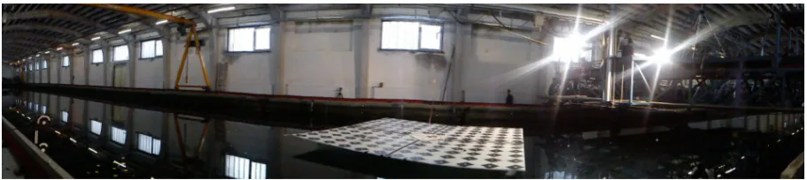
Figure 1: Vienna Model Basin. The central part is occupied by the observed platform. Camera system is placed next to the lamps.
Filter (KF) to detect their anomalous behaviour. The anomalous behaviour meaning: (i) wrong centroiding due to glittering effect, (ii) loss of points due to temporary lack of illumination (point facing away the camera, (iii) loss of points due to temporary oc-clusions (cf. Fig. 2).
Since the arrival of the KF in 1960, it has found applications in many fields, most notably in process control, navigation and tracking. KF is a data processing algorithm that recursively es-timates a time-controlled model. Put differently, it is a weighted least squares estimate of the actual model, estimated upon a vec-tor of real measurementsZ(direct,indirect) with their uncertain-ties and a vector of measurements predicted by the current model state (3), also including its uncertainties. In mathematical terms there is atime-updateequation (2) that projects the current state
ˆ
X(k−1)and error covarianceP(k−1)forward to ana priori esti-mate, and ameasurement-updateequations that serve as feedback to upgrade thea proriestimate to ana posteriorione (6), (7) . In thispredictor-corrector mode of operation, the filter is said to produce a result that is the maximum likelihood estimate. The scope of the paper does not cover detailed mathematics of the Kalman filter, for that the reader is refered to (Maybeck, 1979, Welch and Bishop, 1995, Mehrotra and Mahapatra, 1997). KF describes the model’s state process with a descret linear dif-ference equation (time-update):
ˆ
X−(k)=AXˆ(k−1)+BU(k−1)+W(k−1) (2)
p(W)∼N(0,Q)
predicts the future measurement on its basis:
Z− (k)=HXˆ
−
(k)+V(k−1) (3)
p(V)∼N(0,R)
and projects the error covariance forward:
P−
k =AP(k−1)A T
+Q (4)
whereAis the transfer matrix,Hthe measurement matrix. The
wkandvkare assumed uncorrelated, normally distributed. The most optimal model estimate (7) is a linear combination of the predicted state and the difference between a real observation and its model prediction (innovation) weighted by the Kalman gain (5). The gain minimizes a posteriori error covariance.
Kk=P−
Since we allow our image points to (i) manoeuvre freely, (ii) ac-celerate and (iii) deac-celerate, the motion is described using a jerk model. The state vector consists of 2D position, velocity, accel-eration and jerk:
To use KF as a remedy for spotting bad data, we inspect the innovationvalues. When the discrepancy between the model pre-diction and actual measurement is above a certain threshold, the measurement is either discarded, or replaced with the prediction for continuation purposes. Since KF works as an interpolator, we use it exclusively for detection of erroneous behaviour. We do not ”correct” our measurements with the computed estimates.
a) b) c) d)
Figure 2: Reasons for lost tracking; a) temporary occlusions, b-d) point’s normal moving away from camera’s Line of Sight.
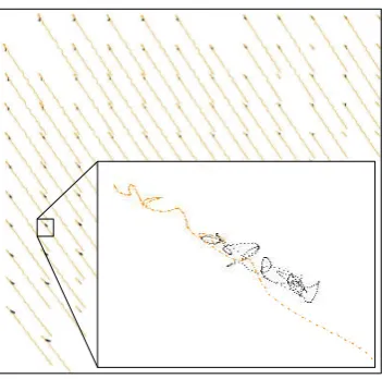
Figure 3: A set of reconstructed points (4D), inorangebefore and in black after the motion correction, cameras moving away from the object. The close-up figure: trajectory before motion subtraction overlaid with the corrected one; trajectories split up when cameras moved.
2.4 Dynamic referencing
At times the constancy of orientation elements is violated and cameras must be dynamically referenced to be able to align mea-surements from different epochs. Typical circumstances are (i) when the measurement volume must be enlarged during the mea-surement to compensate for the movement of the measured ob-ject, or (ii) when the working environment conditions such as vibration affect the camera system position (image-variant inte-rior orientation not reviewed hereafter). Rotations and transla-tions of the cameras are then considered unknowns, or observed unknowns. Their continuous restoration is possible when (i) a reference body is placed in the object scene, (ii) any static well-identifiable objects are present in the object scene, (iii) parame-ters’ differences are observed by external sensors. The beauty of bundle adjustment permits then to combine all this information and output most optimal estimates of current camera positions. When a reference body or external reference frame is available, transforming the measurements to the same datum can be com-puted via (i) 2D-3D resectioning in monocular measurements, or in the multi-ocular case as (ii) sequential 3D-3D spatial similar-ity transformation and (iii) 2D-2D-...-3D simultaneous bundle ad-justment. In either scenario the prerequisite is that the minimum of 3 static points can be observed (Kager, 2000, Wrobel, 2001, B¨osemann, 2011).
In analysing image sequences from multi-ocular systems, the num-ber of unknowns is desired to be kept small. Also, designing a reference frame is often not feasible due to working conditions,
(i) possibilities to include control information in proximity of water were limited,
(ii) one of the cameras could not see any control information (cf. Figure 2),
(iii) the system of cameras was regarded rigid,
we resolved the motion of cameras as a series of sequential 3D-3D orientations. The following workflow was adopted:
xy- image space;
xyz- local frame (before motion correction); XYZ- global frame (after motion correction);
GCP- control information;
input : images, self-calibration output: 4D points (XYZin time)
fori= 1inall frames:
if motion==1:
xyzi=
ADJUST(xyi)
modeli=MODEL(xyzi,EORi−1model)
XYZi=ADJUST(GCP,EORimodel,xyz i
) else:
XYZi=ADJUST(xyi)
Algorithm 1:Pseudocode of dynamic referencing.
Self-calibration parameters and images extracted from videos con-stitute the input to the algorithm. Whenever a change in control information in image space is recorded, and later confirmed by sufficient cues, points intersected at this instant are regarded lo-cal, and are attributed to a 3D local coordinate system -MODEL (cf. Figure 4 b). AMODELis related to the global frame by a spa-tial similarity transformation (Equation (1) withc=−z,λ= 1, ∆x= 0,∆y= 0), hence it stores respective reference parame-ters and a collection of 3D observations. To ”subtract” the camera motion from the total motion, and obtain the global object points, least square adjustment is carried out (cf. Figure 4c). The basis for the transformation is the static, control information registered in both systems. Figure 3 illustrates the principle on real data.
a) b) c)
Figure 4: Dynamic referencing, a) camera motion and object motion occured, b) point reconstruction in the local camera frame, c) points after the spatial similarity camera motion correction
Figure 5: Evaluation of the results with static camera system; inredlow-cost system, in black motion capture system a) definition of ship motions, b-c) rotational part, d-f) translational part of the motion.
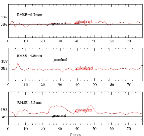
Figure 6: Evaluation of the results with dynamic referenc-ing. The diagrams show discrepancies of three scale bars (top,middle,bottom) between theirreconstructedand their nomi-nal values, over duration of 70 frames. The lengths are given in mm.
3 EVALUATION
The measured object was a 4m x 4m leightweight platform, mark-ed with 144 retroreflective targets. It was suspendmark-ed above the water surface thanks to four submerged air cushions. The ex-periments were performed in two series when (i) regular and (ii) irregular waves were induced. Dynamic referencing was adopted only in irregular wave conditions. Ultimate object precision amou-nted to 4mm (mean value), corresponding to a relative accuracy of 1:2500, at average image scale of 1:500.
In parallel to the operation of the low-cost system, the platform was observed by an online motion capture system, of superior spatial and doubled temporal resolution. The two systems used independent targeting impeding their direct comparison. In ship hydromechanics, analysing dynamics of bodies and fluids in regular waves is usually described in terms ofship motions. The motions can be split into three mutually perpendicular trans-lations around a COG, and three rotations around respective axes (rendered in Figure 5a). The axes convention is:Xaxis in the di-rection of wave propagation,Zpointing upwards, perpendicular to still water surface (Journe and Pinkster, 2002).
With this in mind, the accuracy of the results (i) in regular wave conditions (static) were validated using the calculatedship mo-tions(cf. Figure 5), and (ii) in the irregular spectrum (dynamic) the reconstructed scale bars were compared with their nominal values (cf. Figure 6).
As a preprocessing step in comparing theship motions, the low-cost signals were upsampled to match the frequency of the mo-tion capture system, and cross correlated for fine synchronisamo-tion. The evaluated translational part agrees to a high degree. The sway values come the closest to each other, while the others two dif-fer more significantly, nonetheless within the range of precision given by the adjustment output. The reason for this happening is unfavourable imaging configurations: cameras disposed along theY axis, with little offsets alongXandZ. Roll and pitch (no
With respect to the dynamic referencing, the accuracy evaluation is also optimistic, and within the range of adjustment precision. The constant trend suggests that the system does not drift as the motion proceeds.
4 CONCLUSIONS
The work demonstrates a complete workflow to use off-the-shelf videogrammetry in industrial optical metrology. The outcome proves that the cameras have the potential to become measuring devices, yet their shortcomings must be realized. The portabil-ity of the system, as well as flexibilportabil-ity in targetting and the form of the delivered results were appreciated by the project partners. Noteworthy, if the system was to be set up to be operational for non-expert users, the flexibility would be in large part reduced. Adopting the method of moved reference bar to calibrate the system at once, ousted the laborious image acquisition involved in individual calibrations. Random bar arrangements within the measurement volume proved feasible of recovering instantaneous interior orientation and distortion parameters.
The diminished image quality resulting from lossy compression (H.264) of standard video format turned to be an obstacle in con-tinuous tracking in image space. To mitigate the problem, the target motion model was introduced and modelled in time with the Kalman Filter. Due to the recursive nature of the filter, the additional computations involved did not slow down the tracking process.
In evaluating the reliability of the obtained results, accuracy, rather than precision, was of primary interest. The static and dynamic referencing using spatial similarity transformation gave viable re-sults. In the latter case, the trend of evaluated scale bar lengths indicates that no drift of the camera system exists as the motion proceeds. It is essential to note that appropriate distribution of control information, at best encompassing the object volume, is a prerequisite in obtaining reliable outcomes.
Future works involve more in-depth investigations of the achieved results, as well as forming best practices to handle off-the-shelf videogrammetry in optical metrology, keeping the accuracy as the highest priority.
ACKNOWLEDGEMENTS
This research was funded by FFG Austrian Research Promotion Agency Project no. 832011 and the doctoral college Energy Sys-tems 2030 (ENSYS2030) of Vienna University of Technology.
REFERENCES
Benning, W., Lange, J., Schwermann, R., Effkemann, C. and Grtz, S., 2004. Monitoring crack origin and evolution at con-crete elements using photogrammetry. In: International Archives of the Photogrammetry, Remote Sensing and Spatial Information Sciences 35 (W5), pp. 678–683.
B¨osemann, W., 1996. The optical tube measurement system OLM - photogrammetric methods used for industrial and pro-cess control. In: International Archives of the Photogrammetry,
Clarke, T. and Fryer, J., 1998. The development of camera cal-ibration methods and models. Photogrammetric Record 16(91), pp. 51–66.
Detchev, I., Habib, A. and Elbadry, M., 2013. Dynamic beam de-formation measurements with off-the-shelf digital cameras. Jour-nal of Applied Geodesy 7, pp. 147–157.
El-Hakim, S., Gonzo, L., Voltolini, F., Girardi, S., Rizzi, A., Re-mondino, F. and Whiting, E., 2007. Detailed 3d modelling of castles. International Journal of Architectural Computing 5(2), pp. 199–220.
Fraser, C., 2012. Automatic camera calibration in close-range photogrammetry. In: Proc. ASPRS, Sacramento, CA, USA.
Journe, J. and Pinkster, J., 2002. Introduction in ship hydrome-chanics. Available online athttp://www.shipmotions.nl/ DUT/LectureNotes; visited on Dec 2013.
Kager, H., 2000. Orient User Manual. Institute of Photogramme-try and Remote Sensing, Vienna University of Technology, Aus-tria.
Koschitzki, R., Schacht, G., Schneider, D., Marx, S. and Maas, H. G., 2011. Integration of photogrammetry and acoustic emis-sion analysis for assessing concrete structures during loading test-ing. In: Proc. SPIE, Videometrics, Range Imaging, and Applica-tions XI, Vol. 8085, pp. 0I–I8.
Kraus, K., 1997. Photogrammetry - Advanced Methods and Ap-plications. Vol. 2, D¨ummler Verlag, Germany.
Lin, S.-Y., Mills, J. and Gosling, P., 2008. Videogrammetric mon-itoring of as-built membrane roof structures. Photogrammetric Record 23(122), pp. 128–147.
Luhmann, T., 2010. Close range photogrammetry for industrial applications. ISPRS Journal of Photogrammetry and Remote Sensing 64(3), pp. 558–569.
Maas, H.-G., 1998. Image sequence based automatic multi-camera system calibration techniques. In: International Archives of Photogrammetry and Remote Sensing, Vol. 32(5).
Maas, H.-G., 2008. Close range photogrammetry sensors. Ad-vances in Photogrammetry, Remote Sensing and Spatial Infor-mation Science: 2008 ISPRS Congress Book, CRC Press, Boca Raton, FL, USA.
Maas, H.-G. and Hampel, U., 2006. Photogrammetric tech-niques in civil engineering material testing and structure moni-toring. Photogrammetric Engineering and Remote Sensing 72(1), pp. 39–45.
Maybeck, P., 1979. Stochastic Models, Estimation, and Control. Vol. 1, Academic Press Inc.
Mehrotra, K. and Mahapatra, P., 1997. A Jerk Model for tracking highly maneuvering targets. IEEE Transactions on Aerospace and Electronic Systems 33(4), pp. 1094–1105.
Menna, F. and Troisi, S., 2010. Low cost reverse engineering techniques for 3D modelling of propellers. In: International Archives of the Photogrammetry, Remote Sensing and Spatial In-formation Sciences 38 (Part B5), pp. 452–457.
Meyer, C. G., 2005. In-vacuum photogrammetry of a 10-meter solar sail. American Institute of Aeronautics and Astronautics Paper 2005-1889.
Mostofi, N., Samadzadegan, F., Roohy, S. and Nozari, M., 2012. Using vision metrology system for quality control in automotive industries. In: International Archives of the Photogrammetry, Remote Sensing and Spatial Information Sciences 39 (Part B5), pp. 33–37.
Nocerino, E., Ackermann, S., Pizzo, D., Menna, F. and Troisi, S., 2011. Low-cost human motion capture system for postural analysis onboard ships. In: Proc. SPIE, Videometrics, Range Imaging, and Applications XI, Vol. 8085.
Otepka, J., 2004. Precision Target Mensuration in Vision Metrol-ogy. PhD thesis, Technische Universti¨at Wien.
Pappa, R. S., Jones, T. W., Black, J. T., Walford, A., Robson, S. and Shortis, M. R., 2002. Photogrammetry methodology devel-opment for gossamer spacecraft structures. American Institute of Aeronautics and Astronautics Paper 2002-1375.
Remondino, F. and Fraser, C., 2006. Digital camera calibra-tion methods: consideracalibra-tions and comparisons. In: Internacalibra-tional Archives of the Photogrammetry, Remote Sensing and Spatial In-formation Sciences 36 (Part 5), pp. 266–272.
Remondino, F., Barazzetti, L., Nex, F., Scaioni, M. and Sarazzi, D., 2013. UAV photogrammetry for mapping and 3D modeling -current status and future perspectives. In: International Archives of the Photogrammetry, Remote Sensing and Spatial Information Sciences 38 (1/C22).
Schneider, J., L¨abe, T. and F¨orstner, W., 2013. Incremental real-time bundle adjustment for multi-camera systems with points at infinity. In: International Archives of the Photogrammetry, Re-mote Sensing and Spatial Information Sciences XL-1 (W2).
Shortis, M., Clarke, T. and Robson, S., 1995. Practical testing of the precision and accuracy of target image centring algorithms. In: Proc. SPIE, Videometrics IV, Vol. 2598, pp. 65–76.
Shortis, M. R. and Johnston, G. H. G., 1996. Photogrammetry: An available surface characterization tool for solar concentrators, part I: Measurement of surfaces. ASME Journal of Solar Energy 118, pp. 146–150.
T.Luhmann, S.Robson, S.Kyle and I.Harley, 2011. Close Range Photogrammetry and Machine Vision. Whittles Publishing, UK.
van den Heuvel, F., Verwaal, R. and Beers, B., n.d. Calibration of fisheye camera systems and the reduction of chromatic aberra-tion. In: International Archives of the Photogrammetry, Remote Sensing and Spatial Information Sciences XXXVI/5.
Welch, G. and Bishop, G., 1995. An introduction to the kalman filter.
Wiora, G., Babrou, P. and Manner, R., 2004. Real time high speed measurement of photogrammetric targets. In: Lecture notes in Computer Science, pp. 562–569.
Wrobel, B., 2001. Minimum solutions for orientation. In: Calibration and Orientation of Cameras in Computer Vision, Springer, pp. 7–62.