77 PHYWE Systeme GmbH &Co. KG · D - 37070 Göttingen Laboratory Experiments Physics
Principle:
A partial packet of radiation passes directly from a fixed ultrasonic transmitter to a fixed ultrasonic re-ceiver. A further partial packet hits against a metal screen that is posi-tioned parallel to the connecting line between the transmitter and receiv-er, and is reflected in the direction of the receiver. The two packets of radi-ation interfere with each other at the receiver. When the reflector is moved parallel to itself, the differ-ence in the path lengths of the two packets changes. According to this difference, either constructive or de-structive interference occurs.
The received signal as a function of the reflector distance d.
Tasks:
1. The sliding device is to be used to move the reflector screen posi-tioned parallel to the connecting line between the transmitter and receiver parallel to itself in steps of d = (0.5-1) mm. The reflector
voltage U is to be recorded at each step.
2. The d values of the various maxi-ma and minimaxi-ma are to be deter-mined from the U= U(d) graph
and compared with the theoreti-cally expected values.
What you can learn about …
Longitudinal waves
Power supply f. ultrasonic unit, 5 VDC, 12 W 13900.99 1 Ultrasonic transmitter on stem 13901.00 1 Ultrasonic receiver on stem 13902.00 1
Digital multimeter 07134.00 1
Optical profile-bench, l= 60 cm 08283.00 1
Base f. opt. profile-bench, adjust. 08284.00 2 Slide mount f. opt. profile-bench, h= 80 mm 08286.02 2
Slide mount f. opt. profile-bench 08286.00 1 Sliding device, horizontal 08713.00 1
Swinging arm 08256.00 1
Screen metal, 30⫻30 cm 08062.00 1
Measuring tape, 2 m 09936.00 1
Connecting cord, l= 50 cm, red 07361.01 1
Connecting cord, l= 50 cm, blue 07361.04 1
What you need:
Complete Equipment Set, Manual on CD-ROM included
Interference of ultrasonic waves
Related topics
Longitudinal waves, superposition of waves, reflection of lon-gitudinal waves, interference.
Principle
A partial packet of radiation passes directly from a fixed ultra-sonic transmitter to a fixed ultraultra-sonic receiver. A further partial packet hits against a metal screen that is positioned parallel to the connecting line between the transmitter and receiver, and is reflected in the direction of the receiver. The two packets of radiation interfere with each other at the receiver. When the reflector is moved parallel to itself, the difference in the path lengths of the two packets changes. According to this differ-ence, either constructive or destructive interference occurs.
Equipment
Ultrasonic unit 13900.00 1
Power supply f. ultrasonic unit, 5 VDC, 12 W 13900.99 1 Ultrasonic transmitter on stem 13901.00 1
Ultrasonic receiver on stem 13902.00 1
Digital multimeter 07134.00 1
Optical profile-bench, l= 60 cm 08283.00 1 Base f. opt. profile-bench, adjust. 08284.00 2 Slide mount f. opt. profile-bench, h= 80 mm 08286.02 2 Slide mount f. opt. profile-bench 08286.00 1
Sliding device, horizontal 08713.00 1
Swinging arm 08256.00 1
Screen metal, 30x30 cm 08062.00 1
Measuring tape, 2 m 09936.00 1
Connecting cord, l = 50 cm, red 07361.01 1 Connecting cord, l = 50 cm, blue 07361.04 1
Tasks
1. The sliding device is to be used to move the reflector screen positioned parallel to the connecting line between the transmitter and receiver parallel to itself in steps of d= (0.5-1) mm. The reflector voltage U is to be recorded at each step.
2. The dvalues of the various maxima and minima are to be determined from the U = U(d) graph and compared with the theoretically expected values
Set-up and procedure
Set up the experiment as shown in Fig. 1, referring to the dia-gram in Fig. 2 for more clarity.
Mount the ultrasonic transmitter and the ultrasonic receiver in their slide mounts (h= 80 mm). Set them at the same height, then orient them on the optical bench so that their middle axes are concordant and in alignment with the optical bench. Use the swinging arm to mount the reflector screen on the sliding device (horizontal) and ensure that the slide of this is initially situated at the start of the scale
At the start of the experiment the reflector screen must be aligned parallel to the optical bench and at a distance of 2 cm from the middle axis of the transmitter and receiver. Carry out this adjustment by turning the swinging arm, keeping the reflector parallel to the optical bench while doing so.
21520-00 PHYWE series of publications • Laboratory Experiments • Physics • © PHYWE SYSTEME GMBH & Co. KG • D-37070 Göttingen 2
Finally move the transmitter and receiver so that their front edges are symmetrical to the sides of the screen and at a dis-tance of 29.4 cm apart (see Fig. 2). As the active parts of the ultrasonic elements are approx. 3 cm behind their protective grids, their effective distance apart is now 30 cm.
Connect the transmitter to the TR1 diode socket of the ultra-sonic unit and operate it in continuous mode “Con“. Connect the receiver to the left BNC socket (prior to the amplifier). Connect the signal received to the analog output of the digital multimeter to have it displayed subsequent to amplification and rectification. To ensure proportionality between the input signal and the analog output signal, avoid operating the
ampli-fier in the saturation range. Should such a case occur and the “OVL“ diode light up, reduce either the transmitter amplitude or the input amplification. To start with, for control and avoid-ance of overloading, use the sliding device to bring the screen to the area of the 1st maximum of the measurement curve. To now record the measurement curve, use the sliding device to move the screen away from the middle axis of the system in steps of ∆d = (0.5 – 1) mm, measuring the appropriate receiver voltage U at each step. The results of such a mea-surement series are shown in Fig. 3.
Theory and evaluation
Fig. 4 shows the paths of the partial packets from the sound wave emitted by the transmitter which interfere with each other at the receiver. Part of the wave reaches the receiver directly, whereas a second part is first reflected by a metal screen. According to the difference in the path lengths of the two packets either constructive or destructive interference occurs. With a constant distance between transmitter and receiver, the difference in the paths lengths ∆(and with this the interference conditions) is a function of the distance dof the reflector from the middle axis (see Fig. 4).
The following is valid:
(1)
Constructive interferences (maxima) are given, when ∆ corre-sponds to a whole-numbered wavelength of the ultrasonic wave:
(2)
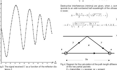
Destructive interferences (minima) are given, when ∆ corre-sponds to an odd-numbered half-wavelength of the ultrason-ic wave:
Fig.3: The signal received Uas a function of the reflector dis-tance d.
Fig.4: Diagram for the calculation of the path length difference of the two partial packets
(t = transmitter, r = receiver, sc = screen) Fig. 2: Diagram of the experimental set-up
Table 1 lists the dvalues for the maxima and minima in Fig. 4, and also, for comparison purposes, the d values calculated using equations (2) and (3)..
Table 1: dvalues at the maxima and minima
The following values were used to calculate d: x= 15.0 cm and l= 0.86 cm.
As the transmitter emits at a frequency of f= 40 Hz, it follows from c= l · f (c= 343.4 ms-1at T= 20°C) that the ultrasound
wavelength is: l= 0.858 cm 0.86 cm.
As only the dvalues of the extremes are determined in this experiment and not their absolute intensity, factors such as absorption by air and the type of wave (plane or spherical) need not be considered here.
⬵
Maxima Minima
n dexp./cm dtheor./cm dexp./cm dtheor./cm
0 0 2.50 2.55
1 3.55 3.62 4.35 4.44
2 5.00 5.15 5.60 5.78
3 6.15 6.35 6.65 6.88