Software Architecture Patterns
Understanding Common Architecture Patterns and When to UseThem
Software Architecture Patterns
by Mark Richards
Copyright © 2015 O’Reilly Media, Inc. All rights reserved. Printed in the United States of America.
Published by O’Reilly Media, Inc., 1005 Gravenstein Highway North, Sebastopol, CA 95472.
O’Reilly books may be purchased for educational, business, or sales promotional use. Online editions are also available for most titles (http://oreilly.com/safari). For more information, contact our corporate/institutional sales department: 800-998-9938 or [email protected].
Editor: Heather Scherer
Production Editor: Colleen Lobner
Copyeditor: Amanda Kersey
Interior Designer: David Futato
Cover Designer: Ellie Volckhausen
Illustrator: Rebecca Demarest
Revision History for the First Edition
2015-02-24: First Release
2015-03-30: Second Release
2017-06-22: Third Release
The O’Reilly logo is a registered trademark of O’Reilly Media, Inc. Software Architecture Patterns, the cover image, and related trade dress are trademarks of O’Reilly Media, Inc.
While the publisher and the author have used good faith efforts to ensure that the information and instructions contained in this work are accurate, the publisher and the author disclaim all responsibility for errors or omissions, including without limitation responsibility for damages resulting from the use of or reliance on this work. Use of the information and instructions contained in this work is at your own risk. If any code samples or other technology this work contains or describes is subject to open source licenses or the
intellectual property rights of others, it is your responsibility to ensure that your use thereof complies with such licenses and/or rights.
Introduction
It’s all too common for developers to start coding an application without a formal architecture in place. Without a clear and well-defined architecture, most developers and architects will resort to the de facto standard traditional layered architecture pattern (also called the n-tier architecture), creating implicit layers by separating source-code modules into packages.
Unfortunately, what often results from this practice is a collection of
unorganized source-code modules that lack clear roles, responsibilities, and relationships to one another. This is commonly referred to as the big ball of mud architecture anti-pattern.
Applications lacking a formal architecture are generally tightly coupled, brittle, difficult to change, and without a clear vision or direction. As a result, it is very difficult to determine the architectural characteristics of the
application without fully understanding the inner-workings of every
component and module in the system. Basic questions about deployment and maintenance are hard to answer: Does the architecture scale? What are the performance characteristics of the application? How easily does the
application respond to change? What are the deployment characteristics of the application? How responsive is the architecture?
Architecture patterns help define the basic characteristics and behavior of an application. For example, some architecture patterns naturally lend
themselves toward highly scalable applications, whereas other architecture patterns naturally lend themselves toward applications that are highly agile. Knowing the characteristics, strengths, and weaknesses of each architecture pattern is necessary in order to choose the one that meets your specific business needs and goals.
Chapter 1. Layered Architecture
The most common architecture pattern is the layered architecture
pattern, otherwise known as the n-tier architecture pattern. This pattern is the de facto standard for most Java EE applications and therefore is widely
known by most architects, designers, and developers. The layered
Pattern Description
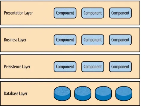
Components within the layered architecture pattern are organized into horizontal layers, each layer performing a specific role within the
application (e.g., presentation logic or business logic). Although the layered architecture pattern does not specify the number and types of layers that must exist in the pattern, most layered architectures consist of four standard layers: presentation, business, persistence, and database (Figure 1-1). In some cases, the business layer and persistence layer are combined into a single business layer, particularly when the persistence logic (e.g., SQL or HSQL) is
embedded within the business layer components. Thus, smaller applications may have only three layers, whereas larger and more complex business applications may contain five or more layers.
Each layer of the layered architecture pattern has a specific role and
responsibility within the application. For example, a presentation layer would be responsible for handling all user interface and browser communication logic, whereas a business layer would be responsible for executing specific business rules associated with the request. Each layer in the architecture forms an abstraction around the work that needs to be done to satisfy a
Figure 1-1. Layered architecture pattern
One of the powerful features of the layered architecture pattern is the
separation of concerns among components. Components within a specific layer deal only with logic that pertains to that layer. For example,
Key Concepts
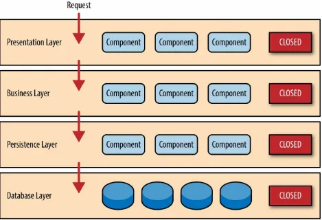
Figure 1-2. Closed layers and request access
So why not allow the presentation layer direct access to either the persistence layer or database layer? After all, direct database access from the presentation layer is much faster than going through a bunch of unnecessary layers just to retrieve or save database information. The answer to this question lies in a key concept known as layers of isolation.
The layers of isolation concept also means that each layer is independent of the other layers, thereby having little or no knowledge of the inner workings of other layers in the architecture. To understand the power and importance of this concept, consider a large refactoring effort to convert the presentation framework from JSP (Java Server Pages) to JSF (Java Server Faces).
Assuming that the contracts (e.g., model) used between the presentation layer and the business layer remain the same, the business layer is not affected by the refactoring and remains completely independent of the type of user-interface framework used by the presentation layer.
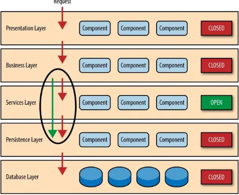
While closed layers facilitate layers of isolation and therefore help isolate change within the architecture, there are times when it makes sense for certain layers to be open. For example, suppose you want to add a shared-services layer to an architecture containing common service components accessed by components within the business layer (e.g., data and string utility classes or auditing and logging classes). Creating a services layer is usually a good idea in this case because architecturally it restricts access to the shared services to the business layer (and not the presentation layer). Without a separate layer, there is nothing architecturally that restricts the presentation layer from accessing these common services, making it difficult to govern this access restriction.
In this example, the new services layer would likely reside below the business layer to indicate that components in this services layer are not accessible from the presentation layer. However, this presents a problem in that the business layer is now required to go through the services layer to get to the persistence layer, which makes no sense at all. This is an age-old problem with the
layered architecture, and is solved by creating open layers within the architecture.
Figure 1-3. Open layers and request flow
Leveraging the concept of open and closed layers helps define the
Pattern Example
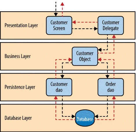
To illustrate how the layered architecture works, consider a request from a business user to retrieve customer information for a particular individual as illustrated in Figure 1-4. The black arrows show the request flowing down to the database to retrieve the customer data, and the red arrows show the
response flowing back up to the screen to display the data. In this example, the customer information consists of both customer data and order data (orders placed by the customer).
The customer screen is responsible for accepting the request and displaying the customer information. It does not know where the data is, how it is
retrieved, or how many database tables must be queries to get the data. Once the customer screen receives a request to get customer information for a particular individual, it then forwards that request onto the customer delegate
module. This module is responsible for knowing which modules in the
Figure 1-4. Layered architecture example
Considerations
The layered architecture pattern is a solid general-purpose pattern, making it a good starting point for most applications, particularly when you are not sure what architecture pattern is best suited for your application. However, there are a couple of things to consider from an architecture standpoint when choosing this pattern.
The first thing to watch out for is what is known as the architecture sinkhole anti-pattern. This anti-pattern describes the situation where requests flow through multiple layers of the architecture as simple pass-through processing with little or no logic performed within each layer. For example, assume the presentation layer responds to a request from the user to retrieve customer data. The presentation layer passes the request to the business layer, which simply passes the request to the persistence layer, which then makes a simple SQL call to the database layer to retrieve the customer data. The data is then passed all the way back up the stack with no additional processing or logic to aggregate, calculate, or transform the data.
Every layered architecture will have at least some scenarios that fall into the architecture sinkhole anti-pattern. The key, however, is to analyze the
percentage of requests that fall into this category. The 80-20 rule is usually a good practice to follow to determine whether or not you are experiencing the architecture sinkhole anti-pattern. It is typical to have around 20 percent of the requests as simple pass-through processing and 80 percent of the requests having some business logic associated with the request. However, if you find that this ratio is reversed and a majority of your requests are simple pass-through processing, you might want to consider making some of the architecture layers open, keeping in mind that it will be more difficult to control change due to the lack of layer isolation.
Pattern Analysis
The following table contains a rating and analysis of the common architecture characteristics for the layered architecture pattern. The rating for each
characteristic is based on the natural tendency for that characteristic as a capability based on a typical implementation of the pattern, as well as what the pattern is generally known for. For a side-by-side comparison of how this pattern relates to other patterns in this report, please refer to Appendix A at the end of this report.
Overall agility
Rating: Low
Analysis: Overall agility is the ability to respond quickly to a constantly changing environment. While change can be isolated through the layers of isolation feature of this pattern, it is still cumbersome and time-consuming to make changes in this architecture pattern because of the monolithic nature of most implementations as well as the tight coupling of components usually found with this pattern.
Ease of deployment
Rating: Low
Analysis: Depending on how you implement this pattern, deployment can become an issue, particularly for larger applications. One small change to a component can require a redeployment of the entire application (or a large portion of the application), resulting in
deployments that need to be planned, scheduled, and executed during off-hours or on weekends. As such, this pattern does not easily lend itself toward a continuous delivery pipeline, further reducing the overall rating for deployment.
Testability
Rating: High
Analysis: Because components belong to specific layers in the
is relatively easy to test. A developer can mock a presentation
component or screen to isolate testing within a business component, as well as mock the business layer to test certain screen functionality. Performance
Rating: Low
Analysis: While it is true some layered architectures can perform well, the pattern does not lend itself to high-performance applications due to the inefficiencies of having to go through multiple layers of the
architecture to fulfill a business request. Scalability
Rating: Low
Analysis: Because of the trend toward tightly coupled and monolithic implementations of this pattern, applications build using this architecture pattern are generally difficult to scale. You can scale a layered
architecture by splitting the layers into separate physical deployments or replicating the entire application into multiple nodes, but overall the granularity is too broad, making it expensive to scale.
Ease of development
Rating: High
Analysis: Ease of development gets a relatively high score, mostly because this pattern is so well known and is not overly complex to
implement. Because most companies develop applications by separating skill sets by layers (presentation, business, database), this pattern
becomes a natural choice for most business-application development. The connection between a company’s communication and organization structure and the way it develops software is outlined is what is
Chapter 2. Event-Driven
Architecture
The event-driven architecture pattern is a popular distributed asynchronous architecture pattern used to produce highly scalable applications. It is also highly adaptable and can be used for small applications and as well as large, complex ones. The event-driven architecture is made up of highly decoupled, single-purpose event processing components that asynchronously receive and process events.
The event-driven architecture pattern consists of two main topologies, the mediator and the broker. The mediator topology is commonly used when you need to orchestrate multiple steps within an event through a central mediator, whereas the broker topology is used when you want to chain events together without the use of a central mediator. Because the architecture characteristics and implementation strategies differ between these two topologies, it is
Mediator Topology
The mediator topology is useful for events that have multiple steps and require some level of orchestration to process the event. For example, a
single event to place a stock trade might require you to first validate the trade, then check the compliance of that stock trade against various compliance rules, assign the trade to a broker, calculate the commission, and finally place the trade with that broker. All of these steps would require some level of orchestration to determine the order of the steps and which ones can be done serially and in parallel.
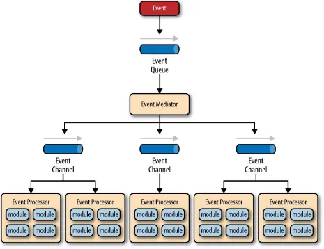
Figure 2-1. Event-driven architecture mediator topology
It is common to have anywhere from a dozen to several hundred event queues in an event-driven architecture. The pattern does not specify the
implementation of the event queue component; it can be a message queue, a web service endpoint, or any combination thereof.
There are two types of events within this pattern: an initial event and a
processing event. The initial event is the original event received by the mediator, whereas the processing events are ones that are generated by the mediator and received by the event-processing components.
that the event mediator doesn’t actually perform the business logic necessary to process the initial event; rather, it knows of the steps required to process the initial event.
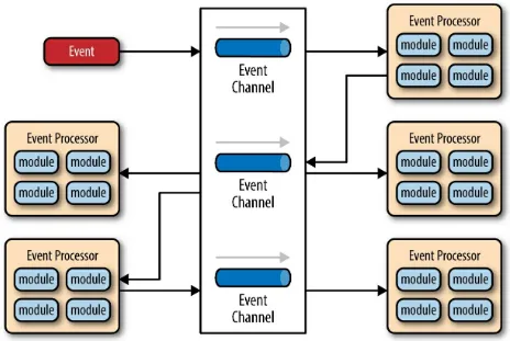
Event channels are used by the event mediator to asynchronously pass
specific processing events related to each step in the initial event to the event processors. The event channels can be either message queues or message topics, although message topics are most widely used with the mediator topology so that processing events can be processed by multiple event processors (each performing a different task based on the processing event received).
The event processor components contain the application business logic necessary to process the processing event. Event processors are self-contained, independent, highly decoupled architecture components that perform a specific task in the application or system. While the granularity of the event-processor component can vary from fine-grained (e.g., calculate sales tax on an order) to coarse-grained (e.g., process an insurance claim), it is important to keep in mind that in general, each event-processor component should perform a single business task and not rely on other event processors to complete its specific task.
The event mediator can be implemented in a variety of ways. As an architect, you should understand each of these implementation options to ensure that the solution you choose for the event mediator matches your needs and requirements.
The simplest and most common implementation of the event mediator is through open source integration hubs such as Spring Integration, Apache Camel, or Mule ESB. Event flows in these open source integration hubs are typically implemented through Java code or a DSL (domain-specific
language). For more sophisticated mediation and orchestration, you can use BPEL (business process execution language) coupled with a BPEL engine such as the open source Apache ODE. BPEL is a standard XML-like
language that describes the data and steps required for processing an initial event. For very large applications requiring much more sophisticated
implement the event mediator using a business process manager (BPM) such as jBPM.
Understanding your needs and matching them to the correct event mediator implementation is critical to the success of any event-driven architecture using this topology. Using an open source integration hub to do very complex business process management orchestration is a recipe for failure, just as is implementing a BPM solution to perform simple routing logic.
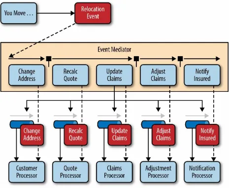
To illustrate how the mediator topology works, suppose you are insured through an insurance company and you decide to move. In this case, the initial event might be called something like relocation event. The steps involved in processing a relocation event are contained within the event mediator as shown in Figure 2-2. For each initial event step, the event
Broker Topology
The broker topology differs from the mediator topology in that there is no central event mediator; rather, the message flow is distributed across the event processor components in a chain-like fashion through a lightweight message broker (e.g., ActiveMQ, HornetQ, etc.). This topology is useful when you have a relatively simple event processing flow and you do not want (or need) central event orchestration.
There are two main types of architecture components within the broker
topology: a broker component and an event processor component. The broker component can be centralized or federated and contains all of the event
Figure 2-2. Mediator topology example
application or providing for future functionality and extensions.
Figure 2-3. Event-driven architecture broker topology
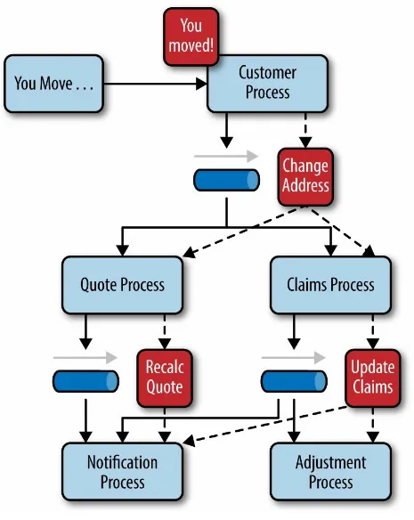
To illustrate how the broker topology works, we’ll use the same example as in the mediator topology (an insured person moves). Since there is no central event mediator to receive the initial event in the broker topology, the
Figure 2-4. Broker topology example
Considerations
The event-driven architecture pattern is a relatively complex pattern to implement, primarily due to its asynchronous distributed nature. When implementing this pattern, you must address various distributed architecture issues, such as remote process availability, lack of responsiveness, and broker reconnection logic in the event of a broker or mediator failure.
One consideration to take into account when choosing this architecture pattern is the lack of atomic transactions for a single business process.
Because event processor components are highly decoupled and distributed, it is very difficult to maintain a transactional unit of work across them. For this reason, when designing your application using this pattern, you must
Pattern Analysis
The following table contains a rating and analysis of the common architecture characteristics for the event-driven architecture pattern. The rating for each characteristic is based on the natural tendency for that characteristic as a capability based on a typical implementation of the pattern, as well as what the pattern is generally known for. For a side-by-side comparison of how this pattern relates to other patterns in this report, please refer to Appendix A at the end of this report.
Overall agility
Rating: High
Analysis: Overall agility is the ability to respond quickly to a constantly changing environment. Since event-processor components are single-purpose and completely decoupled from other event processor
components, changes are generally isolated to one or a few event processors and can be made quickly without impacting other components.
Ease of deployment
Rating: High
Analysis: Overall this pattern is relatively easy to deploy due to the decoupled nature of the event-processor components. The broker topology tends to be easier to deploy than the mediator topology, primarily because the event mediator component is somewhat tightly coupled to the event processors: a change in an event processor
component might also require a change in the event mediator, requiring both to be deployed for any given change.
Testability
Rating: Low
pattern. Performance
Rating: High
Analysis: While it is certainly possible to implement an event-driven architecture that does not perform well due to all the messaging infrastructure involved, in general, the pattern achieves high
performance through its asynchronous capabilities; in other words, the ability to perform decoupled, parallel asynchronous operations
outweighs the cost of queuing and dequeuing messages. Scalability
Rating: High
Analysis: Scalability is naturally achieved in this pattern through highly independent and decoupled event processors. Each event processor can be scaled separately, allowing for fine-grained scalability.
Ease of development
Rating: Low
Chapter 3. Microkernel
Architecture
The microkernel architecture pattern (sometimes referred to as the plug-in architecture pattern) is a natural pattern for implementing product-based applications. A product-based application is one that is packaged and made available for download in versions as a typical third-party product. However, many companies also develop and release their internal business applications like software products, complete with versions, release notes, and pluggable features. These are also a natural fit for this pattern. The microkernel
architecture pattern allows you to add additional application features as plug-ins to the core application, providing extensibility as well as feature
Pattern Description
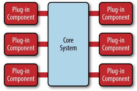
The microkernel architecture pattern consists of two types of architecture components: a core system and plug-in modules. Application logic is divided between independent plug-in modules and the basic core system, providing extensibility, flexibility, and isolation of application features and custom processing logic. Figure 3-1 illustrates the basic microkernel architecture pattern.
Figure 3-1. Microkernel architecture pattern
The plug-in modules are stand-alone, independent components that contain specialized processing, additional features, and custom code that is meant to enhance or extend the core system to produce additional business capabilities. Generally, plug-in modules should be independent of other plug-in modules, but you can certainly design plug-ins that require other plug-ins to be present. Either way, it is important to keep the communication between plug-ins to a minimum to avoid dependency issues.
(AuditChecker), the data contract (input data and output data), and the contract format (XML). It might also contain a WSDL (Web Services Definition Language) if the plug-in is accessed through SOAP.
Plug-in modules can be connected to the core system through a variety of ways, including OSGi (open service gateway initiative), messaging, web services, or even direct point-to-point binding (i.e., object instantiation). The type of connection you use depends on the type of application you are
building (small product or large business application) and your specific needs (e.g., single deploy or distributed deployment). The architecture pattern itself does not specify any of these implementation details, only that the plug-in modules must remain independent from one another.
The contracts between the plug-in modules and the core system can range anywhere from standard contracts to custom ones. Custom contracts are typically found in situations where plug-in components are developed by a third party where you have no control over the contract used by the plug-in. In such cases, it is common to create an adapter between the plug-in contact and your standard contract so that the core system doesn’t need specialized code for each plug-in. When creating standard contracts (usually
Pattern Examples
Perhaps the best example of the microkernel architecture is the Eclipse IDE. Downloading the basic Eclipse product provides you little more than a fancy editor. However, once you start adding plug-ins, it becomes a highly
customizable and useful product. Internet browsers are another common product example using the microkernel architecture: viewers and other plug-ins add additional capabilities that are not otherwise found in the basic
browser (i.e., core system).
The examples are endless for product-based software, but what about large business applications? The microkernel architecture applies to these
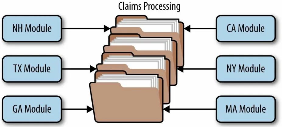
situations as well. To illustrate this point, let’s use another insurance
company example, but this time one involving insurance claims processing. Claims processing is a very complicated process. Each state has different rules and regulations for what is and isn’t allowed in an insurance claim. For example, some states allow free windshield replacement if your windshield is damaged by a rock, whereas other states do not. This creates an almost
infinite set of conditions for a standard claims process.
Not surprisingly, most insurance claims applications leverage large and complex rules engines to handle much of this complexity. However, these rules engines can grow into a complex big ball of mud where changing one rule impacts other rules, or making a simple rule change requires an army of analysts, developers, and testers. Using the microkernel architecture pattern can solve many of these issues.
The stack of folders you see in Figure 3-2 represents the core system for claims processing. It contains the basic business logic required by the insurance company to process a claim, except without any custom
effect on the rest of the core system or other plug-in modules.
Considerations
One great thing about the microkernel architecture pattern is that it can be embedded or used as part of another architecture pattern. For example, if this pattern solves a particular problem you have with a specific volatile area of the application, you might find that you can’t implement the entire
architecture using this pattern. In this case, you can embed the microservices architecture pattern in another pattern you are using (e.g., layered
architecture). Similarly, the event-processor components described in the previous section on event-driven architecture could be implemented using the microservices architecture pattern.
The microservices architecture pattern provides great support for
evolutionary design and incremental development. You can first produce a solid core system, and as the application evolves incrementally, add features and functionality without having to make significant changes to the core system.
Pattern Analysis
The following table contains a rating and analysis of the common architecture characteristics for the microkernel architecture pattern. The rating for each characteristic is based on the natural tendency for that characteristic as a capability based on a typical implementation of the pattern, as well as what the pattern is generally known for. For a side-by-side comparison of how this pattern relates to other patterns in this report, please refer to Appendix A at the end of this report.
Overall agility
Rating: High
Analysis: Overall agility is the ability to respond quickly to a constantly changing environment. Changes can largely be isolated and
implemented quickly through loosely coupled plug-in modules. In general, the core system of most microkernel architectures tends to become stable quickly, and as such is fairly robust and requires few changes over time.
Ease of deployment
Rating: High
Analysis: Depending on how the pattern is implemented, the plug-in modules can be dynamically added to the core system at runtime (e.g., hot-deployed), minimizing downtime during deployment.
Testability
Rating: High
Analysis: Plug-in modules can be tested in isolation and can be easily mocked by the core system to demonstrate or prototype a particular feature with little or no change to the core system.
Performance
Rating: High
high-performance applications, in general, most applications built using the microkernel architecture pattern perform well because you can
customize and streamline applications to only include those features you need. The JBoss Application Server is a good example of this: with its plug-in architecture, you can trim down the application server to only those features you need, removing expensive non-used features such as remote access, messaging, and caching that consume memory, CPU, and threads and slow down the app server.
Scalability
Rating: Low
Analysis: Because most microkernel architecture implementations are product based and are generally smaller in size, they are implemented as single units and hence not highly scalable. Depending on how you
implement the plug-in modules, you can sometimes provide scalability at the plug-in feature level, but overall this pattern is not known for producing highly scalable applications.
Ease of development
Rating: Low
Analysis: The microkernel architecture requires thoughtful design and contract governance, making it rather complex to implement. Contract versioning, internal plug-in registries, plug-in granularity, and the wide choices available for plug-in connectivity all contribute to the
Chapter 4. Microservices
Architecture Pattern
Pattern Description
Regardless of the topology or implementation style you chose, there are several common core concepts that apply to the general architecture pattern. The first of these concepts is the notion of separately deployed units. As illustrated in Figure 4-1, each component of the microservices architecture is deployed as a separate unit, allowing for easier deployment through an
effective and streamlined delivery pipeline, increased scalability, and a high degree of application and component decoupling within your application. Perhaps the most important concept to understand with this pattern is the notion of a service component. Rather than think about services within a microservices architecture, it is better to think about service components, which can vary in granularity from a single module to a large portion of the application. Service components contain one or more modules (e.g., Java classes) that represent either a single-purpose function (e.g., providing the weather for a specific city or town) or an independent portion of a large business application (e.g., stock trade placement or determining
auto-insurance rates). Designing the right level of service component granularity is one of the biggest challenges within a microservices architecture. This
Figure 4-1. Basic Microservices architecture pattern
Another key concept within the microservices architecture pattern is that it is a distributed architecture, meaning that all the components within the
architecture are fully decoupled from one other and accessed through some sort of remote access protocol (e.g., JMS, AMQP, REST, SOAP, RMI, etc.). The distributed nature of this architecture pattern is how it achieves some of its superior scalability and deployment characteristics.
One of the exciting things about the microservices architecture is that it evolved from issues associated with other common architecture patterns, rather than being created as a solution waiting for a problem to occur. The microservices architecture style naturally evolved from two main
sources: monolithic applications developed using the layered architecture pattern and distributed applications developed through the service-oriented architecture pattern.
continuous delivery, the notion of a continuous deployment pipeline from development to production which streamlines the deployment of applications. Monolithic applications typically consist of tightly coupled components that are part of a single deployable unit, making it cumbersome and difficult to change, test, and deploy the application (hence the rise of the common
“monthly deployment” cycles typically found in most large IT shops). These factors commonly lead to brittle applications that break every time something new is deployed. The microservices architecture pattern addresses these
issues by separating the application into multiple deployable units (service components) that can be individually developed, tested, and deployed independent of other service components.
Pattern Topologies
While there are literally dozens of ways to implement a microservices
architecture pattern, three main topologies stand out as the most common and popular: the API REST-based topology, application REST-based topology, and the centralized messaging topology.
The API REST-based topology is useful for websites that expose small, self-contained individual services through some sort of API (application
programming interface). This topology, which is illustrated in Figure 4-2, consists of very fine-grained service components (hence the name
microservices) that contain one or two modules that perform specific
Figure 4-2. API REST-based topology
The application REST-based topology differs from the API REST-based approach in that client requests are received through traditional web-based or fat-client business application screens rather than through a simple API layer. As illustrated in Figure 4-3, the user-interface layer of the application is
deployed as a separate web application that remotely accesses separately deployed service components (business functionality) through simple REST-based interfaces. The service components in this topology differ from those in the API-REST-based topology in that these service components tend to be larger, more coarse-grained, and represent a small portion of the overall business application rather than fine-grained, single-action services. This topology is common for small to medium-sized business applications that have a relatively low degree of complexity.
Figure 4-3. Application REST-based topology
the centralized messaging topology. This topology (illustrated in Figure 4-4) is similar to the previous application REST-based topology except that
instead of using REST for remote access, this topology uses a lightweight centralized message broker (e.g., ActiveMQ, HornetQ, etc.). It is vitally important when looking at this topology not to confuse it with the service-oriented architecture pattern or consider it “SOA-Lite." The lightweight message broker found in this topology does not perform any orchestration, transformation, or complex routing; rather, it is just a lightweight transport to access remote service components.
The centralized messaging topology is typically found in larger business applications or applications requiring more sophisticated control over the transport layer between the user interface and the service components. The benefits of this topology over the simple REST-based topology discussed previously are advanced queuing mechanisms, asynchronous messaging, monitoring, error handling, and better overall load balancing and scalability. The single point of failure and architectural bottleneck issues usually
Avoid Dependencies and Orchestration
One of the main challenges of the microservices architecture pattern is determining the correct level of granularity for the service components. If service components are too coarse-grained you may not realize the benefits that come with this architecture pattern (deployment, scalability, testability, and loose coupling). However, service components that are too fine-grained will lead to service orchestration requirements, which will quickly turn your lean microservices architecture into a heavyweight service-orientedarchitecture, complete with all the complexity, confusion, expense, and fluff typically found with SOA-based applications.
If you find you need to orchestrate your service components from within the user interface or API layer of the application, then chances are your service components are too fine-grained. Similarly, if you find you need to perform inter-service communication between service components to process a single request, chances are your service components are either too fine-grained or they are not partitioned correctly from a business functionality standpoint. Inter-service communication, which could force undesired couplings between components, can be handled instead through a shared database. For example, if a service component handing Internet orders needs customer information, it can go to the database to retrieve the necessary data as opposed to invoking functionality within the customer-service component.
The shared database can handle information needs, but what about shared functionality? If a service component needs functionality contained within another service component or common to all service components, you can sometimes copy the shared functionality across service components (thereby violating the DRY principle: don’t repeat yourself). This is a fairly common practice in most business applications implementing the microservices
Considerations
The microservices architecture pattern solves many of the common issues found in both monolithic applications as well as service-oriented
architectures. Since major application components are split up into smaller, separately deployed units, applications built using the microservices
architecture pattern are generally more robust, provide better scalability, and can more easily support continuous delivery.
Another advantage of this pattern is that it provides the capability to do real-time production deployments, thereby significantly reducing the need for the traditional monthly or weekend “big bang” production deployments. Since change is generally isolated to specific service components, only the service components that change need to be deployed. If you only have a single instance of a service component, you can write specialized code in the user interface application to detect an active hot-deployment and redirect users to an error page or waiting page. Alternatively, you can swap multiple instances of a service component in and out during a real-time deployment, allowing for continuous availability during deployment cycles (something that is very difficult to do with the layered architecture pattern).
Pattern Analysis
The following table contains a rating and analysis of the common architecture characteristics for the microservices architecture pattern. The rating for each characteristic is based on the natural tendency for that characteristic as a capability based on a typical implementation of the pattern, as well as what the pattern is generally known for. For a side-by-side comparison of how this pattern relates to other patterns in this report, please refer to Appendix A at the end of this report.
Overall agility
Rating: High
Analysis: Overall agility is the ability to respond quickly to a constantly changing environment. Due to the notion of separately deployed units, change is generally isolated to individual service components, which allows for fast and easy deployment. Also, applications build using this pattern tend to be very loosely coupled, which also helps facilitate change.
Ease of deployment
Rating: High
Analysis: The deployment characteristics of the microservices pattern rate very high due to the fine-grained and independent nature of the remote services. Services are generally deployed as separate units of software, resulting in the ability to do “hot deployments” any time during the day or night. Overall deployment risk is also significantly reduced, in that failed deployments are able to be restored more quickly and only impact the operations on the service being deployed, resulting in continued operations for all other operations.
Testability
Rating: High
targeted testing efforts. Regression testing for a particular service
component is much easier and more feasible than regression testing for an entire monolithic application. Also, since the service components in this pattern are loosely coupled, there is much less of a chance from a development perspective of making a change that breaks another part of the application, easing the testing burden of having to test the entire application for one small change.
Performance
Rating: Low
Analysis: While you can create applications implemented from this pattern that perform very well, overall this pattern does not naturally lend itself to high-performance applications due to the distributed nature of the microservices architecture pattern.
Scalability
Rating: High
Analysis: Because the application is split into separately deployed units, each service component can be individually scaled, allowing for fine-tuned scaling of the application. For example, the admin area of a stock-trading application may not need to scale due to the low user volumes for that functionality, but the trade-placement service component may need to scale due to the high throughput needed by most trading
applications for this functionality. Ease of development
Rating: High
Analysis: Because functionality is isolated into separate and distinct service components, development becomes easier due to the smaller and isolated scope. There is much less chance a developer will make a
Chapter 5. Space-Based
Architecture
Most web-based business applications follow the same general request
flow: a request from a browser hits the web server, then an application server, then finally the database server. While this pattern works great for a small set of users, bottlenecks start appearing as the user load increases, first at the web-server layer, then at the application-server layer, and finally at the
database-server layer. The usual response to bottlenecks based on an increase in user load is to scale out the web servers. This is relatively easy and
inexpensive, and sometimes works to address the bottleneck issues. However, in most cases of high user load, scaling out the web-server layer just moves the bottleneck down to the application server. Scaling application servers can be more complex and expensive than web servers and usually just moves the bottleneck down to the database server, which is even more difficult and expensive to scale. Even if you can scale the database, what you eventually end up with is a triangle-shaped topology, with the widest part of the triangle being the web servers (easiest to scale) and the smallest part being the
database (hardest to scale).
In any high-volume application with an extremely large concurrent user load, the database will usually be the final limiting factor in how many transactions you can process concurrently. While various caching technologies and
database scaling products help to address these issues, the fact remains that scaling out a normal application for extreme loads is a very difficult
proposition.
Pattern Description
The space-based pattern (also sometimes referred to as the cloud architecture pattern) minimizes the factors that limit application scaling. This pattern gets its name from the concept of tuple space, the idea of distributed shared
memory. High scalability is achieved by removing the central database constraint and using replicated in-memory data grids instead. Application data is kept in-memory and replicated among all the active processing units. Processing units can be dynamically started up and shut down as user load increases and decreases, thereby addressing variable scalability. Because there is no central database, the database bottleneck is removed, providing near-infinite scalability within the application.
Most applications that fit into this pattern are standard websites that receive a request from a browser and perform some sort of action. A bidding auction site is a good example of this. The site continually receives bids from internet users through a browser request. The application would receive a bid for a particular item, record that bid with a timestamp, and update the latest bid information for the item, and send the information back to the browser. There are two primary components within this architecture pattern: a
processing unit and virtualized middleware. Figure 5-1 illustrates the basic space-based architecture pattern and its primary architecture components. The processing-unit component contains the application components (or portions of the application components). This includes web-based
components as well as backend business logic. The contents of the processing unit varies based on the type of application — smaller web-based
applications would likely be deployed into a single processing unit, whereas larger applications may split the application functionality into multiple processing units based on the functional areas of the application. The
processing unit typically contains the application modules, along with an in-memory data grid and an optional asynchronous persistent store for
active processing units.
Figure 5-1. Space-based architecture pattern
The virtualized-middleware component handles housekeeping and
Pattern Dynamics
The magic of the space-based architecture pattern lies in the virtualized middleware components and the in-memory data grid contained within each processing unit. Figure 5-2 shows the typical processing unit architecture containing the application modules, in-memory data grid, optional
asynchronous persistence store for failover, and the data-replication engine. The virtualized middleware is essentially the controller for the architecture and manages requests, sessions, data replication, distributed request
Messaging Grid
The messaging grid, shown in Figure 5-3, manages input request and session information. When a request comes into the virtualized-middleware
component, the messaging-grid component determines which active
Data Grid
The data-grid component is perhaps the most important and crucial
component in this pattern. The data grid interacts with the data-replication engine in each processing unit to manage the data replication between processing units when data updates occur. Since the messaging grid can forward a request to any of the processing units available, it is essential that each processing unit contains exactly the same data in its in-memory data grid. Although Figure 5-4 shows a synchronous data replication between processing units, in reality this is done in parallel asynchronously and very quickly, sometimes completing the data synchronization in a matter of microseconds (one millionth of a second).
Processing Grid
The processing grid, illustrated in Figure 5-5, is an optional component
within the virtualized middleware that manages distributed request processing when there are multiple processing units, each handling a portion of the
application. If a request comes in that requires coordination between processing unit types (e.g., an order processing unit and a customer
processing unit), it is the processing grid that mediates and orchestrates the request between those two processing units.
Deployment Manager
The deployment-manager component manages the dynamic startup and shutdown of processing units based on load conditions. This component continually monitors response times and user loads, and starts up new
Considerations
The space-based architecture pattern is a complex and expensive pattern to implement. It is a good architecture choice for smaller web-based
applications with variable load (e.g., social media sites, bidding and auction sites). However, it is not well suited for traditional large-scale relational database applications with large amounts of operational data.
Although the space-based architecture pattern does not require a centralized datastore, one is commonly included to perform the initial in-memory data grid load and asynchronously persist data updates made by the processing units. It is also a common practice to create separate partitions that isolate volatile and widely used transactional data from non-active data, in order to reduce the memory footprint of the in-memory data grid within each
processing unit.
It is important to note that while the alternative name of this pattern is the cloud-based architecture, the processing units (as well as the virtualized middleware) do not have to reside on cloud-based hosted services or PaaS (platform as a service). It can just as easily reside on local servers, which is one of the reasons I prefer the name “space-based architecture.”
Pattern Analysis
The following table contains a rating and analysis of the common architecture characteristics for the space-based architecture pattern. The rating for each characteristic is based on the natural tendency for that characteristic as a capability based on a typical implementation of the pattern, as well as what the pattern is generally known for. For a side-by-side comparison of how this pattern relates to other patterns in this report, please refer to Appendix A at the end of this report.
Overall agility
Rating: High
Analysis: Overall agility is the ability to respond quickly to a constantly changing environment. Because processing units (deployed instances of the application) can be brought up and down quickly, applications
respond well to changes related to an increase or decrease in user load (environment changes). Architectures created using this pattern
generally respond well to coding changes due to the small application size and dynamic nature of the pattern.
Ease of deployment
Rating: High
Analysis: Although space-based architectures are generally not
decoupled and distributed, they are dynamic, and sophisticated cloud-based tools allow for applications to easily be “pushed” out to servers, simplifying deployment.
Testability
Rating: Low
Analysis: Achieving very high user loads in a test environment is both expensive and time consuming, making it difficult to test the scalability aspects of the application.
Rating: High
Analysis: High performance is achieved through the in-memory data access and caching mechanisms build into this pattern.
Scalability
Rating: High
Analysis: High scalability come from the fact that there is little or no dependency on a centralized database, therefore essentially removing this limiting bottleneck from the scalability equation.
Ease of development
Rating: Low
Analysis: Sophisticated caching and in-memory data grid products make this pattern relatively complex to develop, mostly because of the lack of familiarity with the tools and products used to create this type of
Appendix A. Pattern Analysis
Summary
Figure A-1 summarizes the pattern-analysis scoring for each of the
Figure A-1. Pattern-analysis summary
About the Author
Mark Richards is an experienced, hands-on software architect involved in the architecture, design, and implementation of microservices architectures, service-oriented architectures, and distributed systems in J2EE and other technologies. He has been in the software industry since 1983 and has
Considerations
Pattern Analysis
5. Space-Based Architecture Pattern Description
Pattern Dynamics Messaging Grid
Data Grid
Processing Grid
Deployment Manager
Considerations
Pattern Analysis