Fuzzy Control for Optimizing Ship Tracking
in Karang Jamuang
–
Tanjung Perak
Aulia Siti Aisjah
1, A. A. Masroeri
2, Mohamad Aries Efendi
1, Eko Budi Djatmiko
3,
Wasis Dwi Ariyawan
4, and Fitri Adi Iskandarianto
1Abstract Karang Jamuang West Track - Tanjung Perak is one of the busiest routes for sea transportation in Indonesia. This paper proposes an attempt to optimize the ship’s trajectory by designing a track keeping control along that track line. Control system is designed based on fuzzy logic (FLC). FLC design intended to control the speed and the bow of the ship in order to keep the track. FLC 1 control the speed of the input changing by the distance, while the FLC 2 control the prow with yaw angle and yawrate error input. As an object for autopilot is Brotojoyo MT tanker. The research was done by simulation, and generate the ability of FLC which able to keep the track with small error.
Keywordsautopilot, bow, FLC, speed, track keeping
AbstrakKarang Jamuang, Jalur Barat Tanjung Perak adalah salah satu dari jalur transportasi laut yang paling sibuk di Indonesia. Makalah ini menyarankan sebuah usaha untuk mengoptimalkan lintasan kapal dengan mendesain sebuah jalur yang menjaga kontrol sepanjang garis jalur. Sistem control didesain dengan fuzzy logic (FLC). Desain FLC dimaksudkan untuk mengontrol kecepatan dan haluan kapal untuk menjaga jalur. FLC 1 mengontrol kecepatan dari perubahan input jarak, sedangkan FLC mengontrol haluan dengan sudut penyimpangan dan memasukkan rata-rata sudut penyimpangan. Sebagaimana dalam sebuah objek untuk autopilot dari tanker Brotojoyo MT. Penelitian ini diselesaikan dengan simulasi dan membangkitkan kemampuan dari FLC yang dapat menjada jalur dengan eror yang kecil.
Kata Kunciautopilot, haluan, FLC, kecepatan, menjaga jalur
I.INTRODUCTION1
ea transport as the primary commercial transportation in Indonesia, because the effect of generosity (economics of scale) compared to air transport. On the other hand, The high frequent of marine accidents are: ship sinking, ship collision, fire, problems in the engine and ship leaks. The cause of the accident by JICA, since 1982 to 2000 marine accident occurs once every 2 days, and decreasing began 1989 occurs once every 5 days [1]. Stramindo study has recommended the master plan "Development of Marine Transport Year 2024". In the master plan was prepared coherent shipping modernization effort, which consists of improvements in domestic shipping systems based on traffic demand, shipping regulatory policies and safety, shipping finance institutions, shipping business management modernization, and related maritime industry development.
As an universities effort to solve the problems associated with marine transportation management, has conducted several studies to design the control system of
1 Aulia Siti, Mohamd Aries Efendi, and Fitri Adi Iskandariantoare with
Department of Physics Engineering, Institut Teknologi Sepuluh Nopember (ITS), Surabaya, Indonesia, 60111. Email: [email protected].
2 A. A. Masroeri is with Department of Ship Design Engineering,
Institut Teknologi Sepuluh Nopember (ITS), Surabaya, Indonesia, 60111.
3 Eko Budi Djatmiko is with Department of Ocean Engineering, Institut
Teknologi Sepuluh Nopember (ITS), Surabaya, Indonesia, 60111.
4 Wasis Dwi Ariyawanis with Department of Naval Engineering,
Institut Teknologi Sepuluh Nopember (ITS), Surabaya, Indonesia, 60111.
ship movements / dynamics of both vessels with modern methods and expertise-based [2]. The conventional method began to develop since 1911 of close loop system. Then Minorsky develop it into a PID control system, known as first autopilot, where the control system designed using SISO (Single Input Single Output), with input from the compass and the output is the deflection / rudder movement. Further development is linear steering was derived by Davidson and Schiff, Nomoto, and nonlinier steering by Abkowitz, Norrbin. Design mechanism of the proposed research is a design based on mathematical models of ship dynamics. This way caused some weakness, such as control systems are unable to work when out of range error control inputs, and required gain control justification.
This paper developed an expertise-based control system using fuzzy logic to keep the trajectory target (keeping track) on the Sailing Ship Track Karang Jamuang - Tanjung Perak. As the object of research is the Brotojoyo MT Tanker. Controlled variable is the yaw / heading ships with actuator / driver is the rudder angle.
II.SUPPORTING THEORY A. Ship Dinamic Model
The ship is a sea vehicle with 6 degrees of freedom (DOF). These six displacement components are: surge, sway, heave, roll, pitch and yaw. For ship maneuver dynamics, the variables that influence is expressed in 3 degrees of freedom (dof) and approximated by model 1 dof for yaw motion only, with the assumption that the motion experimentally surge, sway, pitch, roll and heave did not affect ship manuvering [3].
The general form of ship dynamics equations expressed in the form:
L
D
M
(2.1)with
v
[
u
,
v
,
r
]
is the velocity vector. M and D is the inertia matrix and damping which obtained from the linearized equation of forces and moments on the surge, sway and yaw. Speed Equation and steering system of ship will fit based on several assumptions, namely: 1. Mass distribution is homogenuous and xz area is symmetric (Ixy = Iyz = 0)2. heave, roll dan pitch mode ignored (ω = p = q =
=p
=q
= 0 )Based on that assumption, so the surge dinamics, sway dan yaw can be wriiten :
Surge : m(
u
–νr – xGr2) =X (2.3)Sway:m(
+ur+x
Gr
)=Y (2.4) Yaw : Izr
+ mxG(
+ ur) =N (2.5)B. Ship Movement Disturbance Equation
Existence of disturbance factors cause changing the sway velocity ν, yaw velocity changes r and small changes in rudder angle δ. This event may imply that the surge mode can be separated from sway and yaw modes. Thus, it can be assumed that the speed of the sway and yaw is ν0 = r0 = 0. It makes,
u = u0+ Δu; ν = Δν; r = Δr
X = X0 + ΔX; Y = ΔY; N = ΔN (2.6)
Where Δu, Δν dan Δr is disturbance effect from dari
uo, νo dan ro, dan ΔX value, ΔY dan ΔN is disturbance
from X0, Y0 dan N0. It was assumed that the highest orde
from disturbance can be ignore, nonlinear movement equation (2.3, 2.4 dan 2.5) can be written:
m Δu = X0 + ΔX
m(Δ
+ uo Δr + xG Δr) = ΔY (2.7)Iz Δr + mxG(Δ
+ uo Δr) = ΔNNote that the movement equations of the ship steering system has been separated from the speed equation, causing the ship maneuvering equations expressed in terms of the speed equation (2.8) and the steering equation (2.9).
speed equation mu = X (2.8) steering equation m (
+ uo r + xG r) = YIz r + mxG(
+ uo r) = N (2.9)Moments and hydrodynamic force for the three degrees of freedom (surge, sway and yaw), namely: X = X (u,ν, r, u, δ, T)
Y = Y (ν, r, ν, r, δ) (2.10) N = N (ν, r, ν, r, δ)
With T is the propeller power in accordance with a single-screw propeller, for more than one propeller by adding relationships X force equation [3]. By considering the dynamics of the linear steeringsystem (pers. 2. 9), which developed from the linear theory of Davidson and Schiff (1946):
Y = Yυ
+ Yr r + Yυ υ + Yr r + Yδ δRN = Nυ
+ Nr r + Nυ υ + Nr r + Nδ δR (2.11)Therefore it can be written equations of motion (2.11) into the form of matrix equation (2.12) follows.
M
+ N (uo) υ =b δR (2.12)C. Maneuver Ship Transfer Function
Model of ship maneuvering dynamics obtained from the approach taken by Nomoto (1957) as a form of mathematical order 1 and 2. Below is a transfer function model of Nomoto:
s T s T s s T K s RR 1 2
3 1 1 1
(2.13)Parameters from the above transfer function is obtained from the coefficient matrix in equation (2.12) above.
N M T T det det 21 (2.14)
) det( 12 21 21 12 11 22 22 11 2 1 N m n m n m n m n T
T
(2.15) ) det( 2 11 1 21 N b n b n
KR
(2.16) ) det( 2 11 1 21 3 N b m b m T KR (2.17)
Where mij, nij dan bi element ( i = 1,2 dan j = 1,2) in
equation (2.12), M= r z v G r G v N I N mx Y mx Y m ;N(u o)= r G r N u mx N Y mu Y 0 0 (2.18)
Parameter in the determination of the gain control which is derived based on the linearization of the model Nomoto Davidson and Schiff (1946), which form the gain control Nomoto equation is:
) det( 1 11 2 21 N b n b n
K (2.19)
In the matrix M and N above contain hydrodynamic parameters of the ship, where m = mass of the ship, direction = derivative of sway force against, = yaw direction of the force derivative, = derivative of yaw moment on, = derivative of sway force direction of v, = derivative style yaw direction against r, = derivative of sway moments of v, = derivative of sway moment on, = derivative of yaw moment of r, = center of mass. In the strip theory approach Slender body hydrodynamics derivative coefficient can be expressed as a function of length to width ratio of the ship. Smitt (1970), Norrbin (1971) and Inoue (1981) developed an empirical formula of some hydrodynamic coefficient differential equation proposed by Clarke (1982).
a function of length to width ratio of the ship. Smitt (1970), Norrbin (1971) and Inoue (1981) developed an empirical formula of some hydrodynamic coefficient differential equation proposed by Clarke (1982).
D. Ship Speed Transfer Function
Model of ship speed obtained from the approach taken by Horigome, Hara, Hotta and Hotsu (1990) as a form of mathematical order 1. Below is a transfer function of the speed of the ship:
𝑄𝑚
𝑌 (𝑠) =
𝐾𝑦
1 + 𝑇𝑦𝑠
(2.20) Ky is a gain constant and Ty is a time constant. The value
of time constants approximated by the equation:
𝑇𝑦≈ 0.9 2𝜋𝑛 (2.21)
With n is the rotation per second from the propeller as the actuator [2].
E. Ship Flow Disturbance Dynamics Model
There are 3 environment disturbance affect the track keeping, ie currents, winds and waves. Characteristics of disturbances will be different in each shipping region. In the navigation channel Karang Jamuang - Tanjung Perak, assumed the most dominant disorder is current. Other disturbances such as waves and wind are very small because of the geographical location of navigation channel is at a strait . In the model used two-dimensional flow (Fossen, 1994; Vukic, 1998). Current component can be expressed by two parameters: the average flow velocity Vc and the current direction γc. Components of the body-fixed can be calculated from:
uc = Vccos(γc-ψ)
υc = Vcsin(γc-ψ) (2.22)
The average speed of ocean currents for a computer simulation, carried out by using the Gauss-Markov first order process, described by a decrease:
𝑑𝑉𝑐(𝑡)
𝑑𝑡 + 𝜇0𝑉𝑐(𝑡) = 𝜔(𝑡)
(2.23)
with ω (t) is the root of the zero mean Gaussian white noise and μ0 ≥ 0 is a constant. Current models are restricted: Vmin ≤ Vc (t) ≤ Vmax [2].
D. The Turns concept in track keeping
Ships in the maneuver as it passes in a single line to another line along the curved arc around the point trajectory. At the end of these maneuvers are expected next heading must be known to the next straight line segment. If P be a set of points specified path P = {P1, P2, P3, ... Pi, ..., Pn} and the ship moves on Pi-1Pi segment. The ship's position is denoted by the pair (x (t), y (t)), calculated from the equation of ship kinematics. The expected plot point is (xd, yd) = (xi, yi). Heading is expected to be obtained from the equation:
𝜓𝑑 = arctan𝑦𝑑−𝑦(𝑡)𝑥𝑑−𝑥(𝑡) (2.24) It should be noted that the equation is to choose the right quadran Ψd.
Two important parameters that can be observed in Figure 2 is a wheel-over point (WOP*) as a basic model of the wheel-over point (WOP). At that point WOP*
in,
boat stopped moving straight and into the arch of the bow. Reverse procedure happens on the WOP*out.
WOP*in rather than as a starting point of the turning
maneuver, because it is not possible to change the average turn (turning rate) r boat briefly. Wop indicates the beginning of the maneuver and manipulate the distance along a vessel in front of the WOP*in. The
position of the wop defined by using distance ρo = ρo (wop, Pi), depending on the angle φ=<Pi-1PiPi+1. Also
need to note that the heading angle change is expected only at each point of the flow. Therefore, some overshoot can be seen when there are changes in the flow point.
The distance d between the ship's position while the expected path and the point can be calculated from: d=||(xd-x(t),yd-y(t))||
=√(xd-x(t))2+(yd-y(t))2 (2.25)
Heading angle φ=<Pi-1PiPi+1 indicates an angle between
the vectors PiPi+1. Ρo parameters can be determined from
ρo= ρo(φ), as shown in Figure 2. When d> ρo, heading
the expected angle calculated from the relationship (2.24) to (xd,yd) = (xi,yi). If d satisfy d ≤ ρo, the next plot
point can be selected. At that maneuvers around the point Pi flow begins, and ships are doing heading towards the next plot point Pi +1. If i = n, ie there is no plot points are new, the rest of the movement with the expected final heading is determined by the previous segment of Pn-1Pn
[3].
F. Fuzzy Logic Control (FLC) for The bow and Ship Speed
Fuzzy logic control (FLC) provides a methodology for representing, manipulating, and implementing human ways of thinking about how to control a system. Block diagram of a FLC on the bow of the ship as shown in Figure 3 below.
The main components of fuzzy logic control is a fuzzification unit, the unit of fuzzy logic reasoning or fuzzy inference, knowledge base, and the unit defuzzifikasi. There are two types of information contained in the fuzzy knowledge base that is: the data base and rule base. In the database there is the membership function of fuzzy set to be used as the value of each variable system and the rule base to map the fuzzy input values into fuzzy output value. The value of the variable input and output systems are usually in the form of crisp, necessitating surgery fuzzification and defuzzification to map this crisp shape to and from the fuzzy value. What is meant by the form of crisp here is another name for the degree of boolean logic membership only recognize the value 0 dan1.
FLC design consists of several input that is input yaw error (e), yawrate (r), distance and speed. The mechanism of the FLC is based on the input variables are yaw error (e) and yaw rate (r), distance and speed. FLC output control signals fed to the engine steering wheel and then move the ship to the machine direction and position with the speed expected.
An actuator which works under the command of control signals, and the action of the actuator will cause motion in accordance with the desired command. In the description of the movement trajectories fulfilling the above vessel, that the actuator which has been used and are mounted rudder, which has the ability to maintain direction in accordance with the orders. Servo steering gear system consists of two subsystems electrohydraulic steering: telemotor position servo and rudder servo actuator. Input gear servo steering system derived from the autopilot and called the command rudder angle (δc), output in the form of actual rudder angle (δ). In general, Rudder angle and the average rudder for the ship are: δ max=35(deg); 2 1/3(deg/s)≤δmax<7(deg/s), and required that the rudder should be rotating from 35'port to 35 'startboard for 30 seconds (Reid, 1984). Parameter values for servo gear steering system are: the Telemotor: K = 4 (deg / s), DB = 1 (deg), H = 0.8 (deg), and the Rudder servo actuator: N = 5 (deg / s), PB = 7 (deg). Thruster as a driver or drivers of the ship, adjusted for the type of ships to improve ship maneuvering. Thruster unit consists of a transverse-mounted propeller on ships equipped with the electric motor or hydraulic. A propeller is connected to other components to adjust the speed change mechanism. Changes in rotor speed propeller blades represent changes in vessel speed. Designed fuzzy logic control is intended to control the speed through the mechanism of the Thruster. The output of fuzzy logic control of voltage thruster that will change speed according to the expected speed.
III.RESULTS AND DISCUSSION
A. Ship Maneuver Dynamics Modeling and Ship Speed Mathematical model of ship dynamics is obtained from the approach taken by Nomoto (1957) in the form of mathematical order 2. Model Brotojoyo MT tanker dynamics based on the calculations are:
s s s
R
2 3
23 , 33 10,44s
41,45s + 3,52
and ship speed model is obtained from the approach taken by Horigome, Hara, Hotta and Hotsu (1990) as a form of mathematical order 1. The parameters used for modeling is the gain constant (Ky) and time constant, with 𝑇𝑦≈ 0.03768, the mathematical model of ship speed.
𝑄𝑚
𝑌 (𝑠) =
1 1 + 0.03768𝑠
B. Input-Output Data Generation
There are several input and output data used in control system design are:
1. Range of input and output data ψ (range ability to change direction ship), data input range dψ / dt (range ability to change direction vessel per second), data input and output speed range (the range of ship speed) and data range of distances (d) which has decided on designing.
2. Shipping data Karang Jamuang - Tanjung Perak recommended navigation service that is used to test the performance and analysis of control systems that have been designed to track keeping.
3. Characteristics of disturbance data (flow) in the Karang Jamuang Coral - Tanjung Perak shipping. C. Shipping line
Shipping flow Karang Jamuang - Tanjung Perak obtained from Tanjung Perak Adpel Navigation District Surabaya.Data expressed in units of DMS (Degree Minutes Second). In the simulation process, the data path used is the data in XY Cartesian coordinates. Thus changed into the form of XY coordinate conversion value of 1o = 111322. Trajectory is obtained based on the
location of buoys along the path as shown in the picture on the side.
a. Disturbance Generation
For the simulation process flow values generated by using the order 1 Gauss-Markov Process with the algorithm as follows:
1. Initial value : Vc (0) = 0.5 (Vmax + Vmin)
2. Euler integration with a sampling period h Vc (k+1)=
Vc(k) + h Vc(k)
3. Limiter : jika (Vc (k+1)> Vmax) or (Vc (k+1)< Vmin)
so Vc (k+1)= Vc (k)- h Vc(k)
4. k=k+1, back to step 2 b. FLC desinging
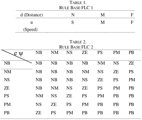
There are 2 control systems are FLC FLC 1 and 2. FLC 1 as control the speed of the ship and FLC 2 as the control of the prow of a ship. Input of FLC 1 is the distance d. Variable d is divided into 3 membership functions of N (Near), M (Medium) and F (Far) with working range (range) used for membership function is 0 to 9000m distance range is determined by the researcher based on calculations in accordance with real conditions. Variable output of FLC1 divided into 3 membership functions of S (Slow), M (Medium), F (Fast) with appropriate speed boats which range between 0 to 5.02 m / s.
There are two variable inputs to FLC 2 that eψ (yaw error) and yaw rate (r). Variable input errors divided into 7 membership functions are NB, NM, NS, ZE, PS, PM, PB, with a range of work (range) used for membership function is -35o to 35o. N is negative, Z is zero, P is
positive, B is big and S is small. As for the variable yaw rate (r) function is divided in 7 sets of membership function that is NB, NM, NS, ZE, PS, PM. N is negative, Z is zero, P is positive, is the Big B and S is Small. Range used is -70 to 70. The determination of this range
based on the characteristics of the rudder Van Amorengen. The output of FLC 2 is a rudder command which is also divided into 7 membership functions such as input yaw error.
D. Rule Base
IV.DATA ANALYSIS AND DISCUSSION A. FLC1 Testing at Brotojoyo MT Tanker
To test how accurate FLC1 in reaching target set of points given the set point tracking test. The fulfillment of the performance test track that was first done by incorporating input from the builder inputs that represent the distance change function of time, as a representative form of the condition of real groove cruise ship whose values can be seen in the picture 5.Selanjutnya distance change becomes an input to FLC1 .
FLC1 works by monitoring the distance changes the coordinates of the ship at the destination point and change the output value if the distance reaches certain values in accordance with rule bases that have been designed. Base rules that have been designed on the concept of turning FLC1 representation is that the ship must be in a speed of 3 knots when the difference between the distance to the target coordinates to reach twice the length of the ship is 500 meters LPP.
The output signal FLC1 is input to the Thruster represented on the ship speed transter function equation. The output of the system shows the system response to the change in control signal issued by FLC1. In Figure 6 shows that FLC change the speed when approaching inflection points indicated by the small distance. System response was very good and to follow changes in input by FLC1 with a very small error value.
B. FLC2 Testing at Tangki Brotojoyo MT Tanker without Disturbance
The performance test in the first track keeping is by inserting the input trajectory of the coordinates of trajectory of Karang Jamuang navigation channel – Tanjung Perak. Coordinates trajectory of units DMS (Degree Minutes Second) which is then converted into Cartesian coordinates. These coordinates represent the flow of the ship trajectory.
In the simulation process, a process that occurs is shown on an XY graph so that it can be analyzed directly in XY plots. There are 2 lines on the XY Graph as in Figure 7 is the first to show desired track or the desired trajectory and the second shows the actual path which is the response of ship maneuvering system. From the
graph below appear to be of the same pattern, this suggests that the controls that are designed to follow trajectory pattern or target trajectory compliance (keeping track). However, if viewed more closely by recording data and compare it with the actual coordinates of the target trajectory and then the plot in Excel as in table 4.2, it appears there was an error path. The occurrence of this trajectory error associated with a less than optimal control design so that there should be more iterations to get the most minimal error. Trajectory error values at each point coordinates are shown in table 3. Categorized small trajectory error given that the dimensions of the ship used in the study of Brotojoyo MT ship has a very large dimensions.
C. FLC2 Testing at Tangki Brotojoyo MT Tanker with Disturbance
In real conditions during the shipping, a ship will not be apart from the factor of disturbance (disturbance) in the form of currents, waves and wind. In the simulation was done with current noise. In addition, provision of this disorder also use to test how robust controls have been designed.
Figure 9 shows the target trajectory and actual trajectory simulation results. From the images could be evaluated that the actual trajectory has a pattern corresponding to the desired trajectory but seen the error as shown in the picture when zoomed and the calculation error table 4. Error when there is greater disruption than without interference at each point of trajectory.
V.CLOSING
Based on research that has been done, the conclusion as follows:
Has been done a design of fuzzy logic controller to control the bow and the speed for this type of MT Brotojoyo tanker which capable of keeping the trajectory in the Port of Tanjung Perak, Surabaya. In the test without disturbaance occurs the maximum
error of 35.09 meters and a minimum error of 0.9 meters, while in testing with disturbance maximum error value of 35.59 meters and a minimum error of 0.84 meters.
Fuzzy logic system has been designed can increase the efficiency of time sailing 38 minutes.
Figure 3. Fuzzy Logic Control Diagram
Figure 4. Simulink Block Diagram for Tracking Test with Disturbance
Figure 6. Ship Speed Respon
Figure 7. Desired Track Graph and Actual Tracks Figure 8. Desired Track Graph and Actual Tracks on the test with on the Test without Disturbance disturbance
TABLE 1.
RULE BASE FLC1
d (Distance) N M F
u
(Speed)
S M F
TABLE 2.
RULE BASE FLC2
NB NM NS ZE PS PM PB
NB NB NB NB NB NM NS ZE
NM NB NB NB NM NS ZE PS
NS NB NB NB NS ZE PS PM
ZE NB NM NS ZE PS PM PB
PS NM NS ZE PS PM PB PB
PM NS ZE PS PM PB PB PB
PB ZE PS PM PB PB PB PB
TABLE 3.
THE FLC2 ERROR CALCULATION ON A TEST TRACK WITHOUT DISTURBANCE
No Xd (desire) Yd (desire) Xa(actual) Ya(actual) Error of trajectory (m)
1 12549144 -771059 12549143 -771059 0,90
2 12546917 -775234 12546913 -775238 5,71
3 12546299 -776254 12546285 -776267 17,79
4 12544134 -779718 12544114 -779737 27,78
5 12541877 -783212 12541856 -783232 28,67
6 12540671 -791654 12540658 -791666 17,59
7 12541537 -793664 12541536 -793664 0,43
8 12543825 -798735 12543836 -798723 17,04
9 12545124 -799818 12545144 -799796 29,18
10 12547536 -800591 12547560 -800565 35,09
11 12549082 -799787 12549102 -799765 29,68
12 12550319 -801147 12550319 -801146 1,81
TABLE 4.
THE FLC2ERROR CALCULATION ON ATEST TRACK WITH DISTURBANCE
No Xd Yd Xa Ya Error of
trajectory (m)
1 12549144 -771059 12549143 -771059 0,84
2 12546917 -775234 12546913 -775238 5,49
3 12546299 -776254 12546286 -776266 17,50
4 12544134 -779718 12544114 -779737 27,81
5 12541877 -783212 12541856 -783232 29,10
6 12540671 -791654 12540658 -791666 17,82
7 12541537 -793664 12541536 -793664 0,90
8 12543825 -798735 12543837 -798722 17,74
9 12545124 -799818 12545144 -799796 29,47
10 12547536 -800591 12547560 -800565 35,59
11 12549082 -799787 12549103 -799764 30,81
12 12550319 -801147 12550322 -801143 4,82
REFERENCES
[1] . Aisjah, A.S., ” Design Of Tracking Ship Control Using Fuzzy Logic for Shipping Effisiensi Case Study : Karang Jamuang –
Tanjung Perak ”, Prosiding Seminar Nasional Teori dan Aplikasi Teknologi Kelautan 2009.
[2] . Aisjah, A.S., Soegiono, Masroeri, AA., Djatmiko, E.B., dan Wasis, D.A, , (2007d), “Analisis Performansi Sistem Kontrol
Pada manuvering Kapal”, Jurnal Teknik Fisika, Vol. 2, No. 1, Februari 2007.
[3] . T. I . Fossen, “Guidance and Control of Ocean vehicles”.
John Wiley & Sons Ltd., 1994.
[4] . Velagic, J., Vukic, Z., Omerdic, E.,”Adaptive Fuzzy Ship Autopilot for Track-Keeping”, 2001.
[5] . Aisjah, A.S, AA. Masroeri, “Perancangan sistem monitoring
dan kontrol cerdas sebagai upaya peningkatan kualitas
trasnportasi laut”, Proceeding SITIA, 14 Oktober 2009. [6] . Aisjah, A.S, Design Of Smart Course Control System Based
On Fuzzy Logic In The Tracking Ship At Tanjung Perak Port
Surabaya, Seminar Nasional 1’st APTECS – ITS, Desember 2009.
[7] . Aisjah, A.S, Increasing The Safety And Efficiency Sea Transportation By Designing Monitoring And Control System
![Figure 1. Six Degrees of Freedom Ship Dynamics [3]](https://thumb-ap.123doks.com/thumbv2/123dok/1636444.1558235/5.595.307.482.613.738/figure-degrees-freedom-ship-dynamics.webp)