i
Universitas Kristen Maranatha
Bass Menjadi Chord yang Ditampilkan Pada LCD
INDRA
Email : [email protected]
Jurusan Teknik Elektro, Fakultas Teknik, Universitas Kristen Maranatha Jalan Prof. drg. Suria Sumantri, MPH 65
Bandung 40164, Indonesia
ABSTRAK
Salah satu hal yang terpenting dalam bermusik adalah koordinasi antara para pemain musik tersebut. Komunikasi antara sesama personil sangatlah dibutuhkan untuk membuat permainan musik menjadi bagus. Kadang kala pada saat latihan komunikasi antara pemain musik cukup terhambat dikarenakan pada saat semua personil memainkan alat musiknya masing-masing, secara bersamaan harus berkomunikasi dalam menyamakan chord dengan pemusik yang lain.
Dalam tugas akhir ini dirancang dan direalisasikan alat untuk mengubah sinyal pada gitar bass menjadi chord yang ditampilkan pada LCD. Input data berupa sinyal dari gitar bass yang diteruskan ke rangkaian penguat yang selanjutnya dikuatkan 10 kali, dikarenakan keluaran gitar bass hanya 0.2-0.5V. Mikrokontroler akan mengubah frekuensi dari sinyal tersebut kemudian mengolahnya lalu ditampilkan pada LCD 2x16 dalam bentuk chord.
ii
Universitas Kristen Maranatha
Design and Realization of Tool to Change Bass Guitar
Signal In Chord and Shown In LCD
INDRA
Email : [email protected]
Jurusan Teknik Elektro, Fakultas Teknik, Universitas Kristen Maranatha Jalan Prof. drg. Suria Sumantri, MPH 65
Bandung 40164, Indonesia
ABSTRACT
One of the most important thing in music is coordination between these musicians. Communication among personnel is needed to make a good music game. Sometimes at practice enough communication between the music player is hampered due at the time of all personnel play a musical instrument, respectively, to communicate simultaneously to equate chord with the other musicians.
In this thesis designed and realized a tool to convert the signal to a bass guitar chord displayed on the LCD. Input data is a signal from the bass guitar which is forwarded to the next amplifier boosted 10 times, because only the bass guitar output 0.2-0.5V. Microcontroller will change the frequency of the signal is then process them and then displayed on the LCD 2x16 in a chord.
v
Universitas Kristen Maranatha
ABSTRAK ... i
ABSTRACT ... ii
KATA PENGANTAR ... iii
DAFTAR ISI ... v
DAFTAR TABEL ... vii
DAFTAR GAMBAR ... viii
DAFTAR LAMPIRAN ... x
BAB I PENDAHULUAN I.1 Latar Belakang Masalah ... 1
I.2 Perumusan Masalah ... 1
I.3 Tujuan ... 1
I.4 Pembatasan Masalah ... 2
I.5 Sistematika Penulisan ... 2
BAB II LANDASAN TEORI II.1. Teori Musik dan Gitar bass ... 3
II.1.1 Tempo ... 4
II.2. Piezo Pick Up ... 4
II.2.1 Cara Kerja Piezo Pick Up ... 5
II.3. Mikrokontroler AVR ATMega16 ... 5
II.3.1 Fitur ATmega16 ... 6
II.3.2 Konfigurasi Pin AVR ATmega16 ... 7
II.3.3 Timer ... 9
II.3.4 Timer 8 bit ... 9
II.3.5 Timer 1 (16bit) ... 10
II.3.6 Prescaler ... 10
II.3.7 Perhitungan Waktu Timer ... 10
II.3.8 Interupsi ... 11
II.3.9 Interupsi Eksternal ... 12
vi
Universitas Kristen Maranatha
II.5. Operasional Amplifier (Op-Amp) ... 14
II.5.1 Inverting Amplifier ... 15
II.5.2 Non-Inverting Amplifier ... 16
BAB III PERANCANGAN DAN REALISASI III.1. Perancangan Hardware ... 18
III.1.1 Perancangan Alat untuk mengubah sinyal pada gitar bass menjadi Chord yang ditampilkan pada LCD ... 19
III.1.2 Input dan Penguat ... 20
III.2. Perancangan Software ... 21
III.2.1 Menghitung Timer dan Prescaler ... 21
III.2.2 Diagram Alir untuk program yang akan dibuat ... 22
BAB IV DATA PENGAMATAN IV.1. Grafik Sinyal Pada Osiloskop ... 27
IV.2. Pengujian Kinerja Alat ... 32
IV.3. Pengujian Alat memainkan nada berurutan (c d e f g a b c) dengan berbagai macam tempo ... 33
IV.4. Pengujian alat memainkan lagu dengan berbagai macam jenis lagu ... 35
IV.5. Pengujian Delay ... 38
IV.6. Analisis Data ... 38
BAB V PENUTUP V.1.Kesimpulan ... 40
V.2.Saran ... 40
vii
Universitas Kristen Maranatha
Tabel 2.1 tabel frekuensi dan notasi ... 3
Tabel 2.2 Fungsi Khusus Port B ... 7
Tabel 2.3 Fungsi Khusus Port C ... 8
Tabel 2.4 Fungsi Khusus Port D ... 8
Tabel 2.5 Interrupt Vektor Pada ATMega 16 ... 11
Tabel 2.6 bit ISC01 dan ISC00 ... 12
Tabel 2.7 Konfigurasi bit ISC11 dan ISC10 ... 13
Tabel 2.8 Tabel kaki LCD ... 14
Tabel 4.1 perbandingan frekuensi percobaan dengan teori ... 31
viii
Universitas Kristen Maranatha
DAFTAR GAMBAR
Gambar 2.1 Sensor Piezo(pick up) yang dipasang pada bass elektrik ... 5
Gambar 2.2 Konfigurasi kaki(pin) ATmega16 ... 7
Gambar 2.3 IC ATmega16 ... 9
Gambar 2.4 Register MCUCR ... 12
Gambar 2.5 General Interrupt Control Register-GICR ... 13
Gambar 2.6 LCD Display ... 14
Gambar 2.7 Rangkaian dasar operasional amplifier (Op-Amp) ... 15
Gambar 2.8 Rangkaian Inverting Amplifier ... 16
Gambar 2.9 Rangkaian Non-inverting amplifier ... 16
Gambar 3.1 Blok Diagram Sistem ... 18
Gambar 3.2 Schematic Perancangan alat untuk mengubah sinyal pada gitar bass menjadi chord yang ditampilkan LCD ... 19
Gambar 3.3 Schematic input dan penguat ... 20
Gambar 3.4 Diagram alir untuk program utama ... 22
Gambar 3.5 Diagram alir interupsi frekuensi ... 23
Gambar 3.6 Diagram alir tampilkan_LCD ... 24
Gambar 4.1 Grafik sinyal nada E ... 27
Gambar 4.2 Grafik sinyal nada F ... 27
Gambar 4.3 Grafik sinyal nada F# ... 27
Gambar 4.4 Grafik sinyal nada G ... 27
Gambar 4.5 Grafik sinyal nada G# ... 27
Gambar 4.6 Grafik sinyal nada A ... 27
Gambar 4.7 Grafik sinyal nada A# ... 28
Gambar 4.8 Grafik sinyal nada B... 28
Gambar 4.9 Grafik sinyal nada C... 28
Gambar 4.10 Grafik sinyal nada C#... 28
Gambar 4.11 Grafik sinyal nada D ... 28
Gambar 4.12 Grafik sinyal nada D# ... 28
ix
Universitas Kristen Maranatha
Gambar 4.15 Grafik sinyal nada F#2 ... 29
Gambar 4.16 Grafik sinyal nada G2 ... 29
Gambar 4.17 Grafik sinyal nada G#2 ... 29
Gambar 4.18 Grafik sinyal nada A2 ... 29
Gambar 4.19 Grafik sinyal nada A#2 ... 30
Gambar 4.20 Grafik sinyal nada B2... 30
Gambar 4.21 Grafik sinyal nada C2... 30
Gambar 4.22 Grafik sinyal nada C#2... 30
Gambar 4.23 Grafik sinyal nada D2 ... 30
Gambar 4.24 Grafik sinyal nada D#2 ... 30
Gambar 4.25 Grafik sinyal nada E3 ... 31
Gambar 4.26 Tampilan pada layar LCD untuk petikan pertama ... 32
Gambar 4.27 Tampilan pada layar LCD untuk petikan kedua ... 32
Gambar 4.28 Tampilan pada layar LCD untuk petikan ketiga ... 32
Gambar 4.29 Tampilan pada layar LCD untuk petikan keempat ... 32
Gambar 4.30 Tampilan pada layar LCD untuk petikan kelima ... 33
Gambar 4.31 Tampilan pada layar LCD untuk petikan keenam... 33
Gambar 4.32 Tampilan pada layar LCD untuk petikan ketujuh ... 33
Gambar 4.33 Tampilan pada layar LCD untuk petikan kedelapan ... 33
Gambar 4.34 Hasil pengujian dengan tempo 40 ... 33
Gambar 4.35 Hasil pengujian dengan tempo 45 ... 34
Gambar 4.36 Hasil pengujian dengan tempo 50 ... 34
Gambar 4.37 Hasil pengujian dengan tempo 55 ... 34
Gambar 4.38 Hasil pengujian dengan tempo 60 ... 34
Gambar 4.39 Hasil pengujian dengan tempo 65 ... 34
Gambar 4.40 Hasil pengujian dengan tempo 70 ... 34
Gambar 4.41 Tampilan Nada Pada LCD, Memainkan Lagu Michael Buble - Home ... 36
x
Universitas Kristen Maranatha Gambar 4.43 Tampilan Nada Pada LCD, Memainkan Lagu Cherry Belle
xi
Universitas Kristen Maranatha
LAMPIRAN A
PROGRAM PADA CODEVISION ... A-1
LAMPIRAN B
Gambar Modul Mikro Yang Digunakan ... B-1 Gambar Modul Penguat ... B-1 Gambar Modul Modul LCD... B-2 Gambar Rancangan Secara Keseluruhan ... B-2 Gambar Bass Yang Digunakan ... B-3
LAMPIRAN C
LAMPIRAN A
A-1
/***************************************************** This program was produced by the
CodeWizardAVR V2.05.7 Evaluation Automatic Program Generator
© Copyright 1998-2012 Pavel Haiduc, HP InfoTech s.r.l. http://www.hpinfotech.com
Project : Version :
Date : 10/2/2012
Author : Freeware, for evaluation and non-commercial use only
Company : Comments:
Chip type : ATmega16 Program type : Application
AVR Core Clock frequency: 8.000000 MHz Memory model : Small
External RAM size : 0 Data Stack size : 256
A-2 float pulsa=0, oldpulsa;;
int brs,ke;
#include <mega16.h> #include <lcd.h> #include <delay.h> #include <stdlib.h>
// Alphanumeric LCD functions #asm
.equ __lcd_port=0x1b ; PORTA #endasm
// Declare your global variables here void tampilkan_LCD();
// External Interrupt 1 service routine interrupt [EXT_INT1] void ext_int1_isr(void) {
frekuensi++;
// Place your code here }
A-3 {
// Reinitialize Timer1 value TCNT1H=0xE17C >> 8; TCNT1L=0xE17C & 0xff; oldpulsa=pulsa; pulsa=frekuensi; frekuensi=0;
if(oldpulsa>pulsa && oldpulsa>=40){ pulsa=oldpulsa;
tampilkan_LCD(); pulsa=0;
} }
// Place your code here void tampilkan_LCD() {
if (pulsa>=80 && pulsa<87) {
lcd_putsf("E "); delay_ms(350); }
else if (pulsa>=40 && pulsa<43) {
A-4 delay_ms(350);
}
else if (pulsa>=43 && pulsa<46) {
lcd_putsf("F "); delay_ms(350); }
else if (pulsa>=46 && pulsa<49) {
lcd_putsf("F#"); delay_ms(350); }
else if (pulsa>=49 && pulsa<52) {
lcd_putsf("G "); delay_ms(350); }
else if (pulsa>=52 && pulsa<54) {
lcd_putsf("G#"); delay_ms(350); }
else if (pulsa>=54 && pulsa<58) {
A-5 delay_ms(350);
}
else if (pulsa>=58 && pulsa<60) {
lcd_putsf("A#"); delay_ms(350); }
else if (pulsa>=60 && pulsa<65) {
lcd_putsf("B "); delay_ms(350); }
else if (pulsa>=65 && pulsa<69) {
lcd_putsf("C "); delay_ms(350); }
else if (pulsa>=69 && pulsa<73) {
lcd_putsf("C#"); delay_ms(350); }
else if (pulsa>=73 && pulsa<77) {
A-6 delay_ms(350);
}
else if (pulsa>=77 && pulsa<81) {
lcd_putsf("D#"); delay_ms(350); }
else if (pulsa>=87 && pulsa<93) {
lcd_putsf("F "); delay_ms(350); }
else if (pulsa>=93 && pulsa<98) {
lcd_putsf("F#"); delay_ms(350); }
else if (pulsa>=98 && pulsa<104) {
lcd_putsf("G "); delay_ms(350); }
else if (pulsa>=104 && pulsa<110) {
A-7 delay_ms(350);
}
else if (pulsa>=110 && pulsa<116) {
lcd_putsf("A "); delay_ms(350); }
else if (pulsa>=116 && pulsa<120) {
lcd_putsf("A#"); delay_ms(350); }
else if (pulsa>=120 && pulsa<129) {
lcd_putsf("B "); delay_ms(350); }
else if (pulsa>=129 && pulsa<140) {
lcd_putsf("C "); delay_ms(350); }
else if (pulsa>=140 && pulsa<146) {
A-8 delay_ms(350);
}
else if (pulsa>=146 && pulsa<156) {
lcd_putsf("D "); delay_ms(350); }
else if (pulsa>=156 && pulsa<165) {
lcd_putsf("D#"); delay_ms(350); }
else if (pulsa>=165 && pulsa<176) {
lcd_putsf("E "); delay_ms(350); }
else if (pulsa>=176 && pulsa<186) {
lcd_putsf("F "); delay_ms(350); }
else if (pulsa>=186 && pulsa<197) {
A-9 delay_ms(350);
}
else if (pulsa>=197 && pulsa<208) {
lcd_putsf("G "); delay_ms(350); }
else if (pulsa>=208 && pulsa<220) {
lcd_putsf("G#"); delay_ms(350); }
else if (pulsa>=220 && pulsa<233) {
lcd_putsf("A "); delay_ms(350); }
else if (pulsa>=233 && pulsa<248) {
lcd_putsf("A#"); delay_ms(350); }
else if (pulsa>=248 && pulsa<264) {
A-10 delay_ms(350);
}
else if (pulsa>=264 && pulsa<280) {
lcd_putsf("F "); delay_ms(350); }
else ke--; ke++; if(ke==9){ lcd_clear(); ke=0; } }
void main(void) {
// Declare your local variables here
// Input/Output Ports initialization // Port A initialization
// Func7=In Func6=In Func5=In Func4=In Func3=In Func2=In Func1=In Func0=In // State7=T State6=T State5=T State4=T State3=T State2=T State1=T State0=T PORTA=0x00;
A-11 // Port B initialization
// Func7=In Func6=In Func5=In Func4=In Func3=In Func2=In Func1=In Func0=In // State7=T State6=T State5=T State4=T State3=T State2=T State1=T State0=T PORTB=0x00;
DDRB=0x00;
// Port C initialization
// Func7=In Func6=In Func5=In Func4=In Func3=In Func2=In Func1=In Func0=In // State7=T State6=T State5=T State4=T State3=T State2=T State1=T State0=T PORTC=0x00;
DDRC=0x00;
// Port D initialization
// Func7=In Func6=In Func5=In Func4=In Func3=In Func2=In Func1=In Func0=In // State7=T State6=T State5=T State4=T State3=T State2=T State1=T State0=T PORTD=0x00;
DDRD=0x00;
// Timer/Counter 0 initialization // Clock source: System Clock // Clock value: Timer 0 Stopped // Mode: Normal top=0xFF // OC0 output: Disconnected TCCR0=0x00;
A-12 OCR0=0x00;
// Timer/Counter 1 initialization // Clock source: System Clock // Clock value: 8000.000 kHz // Mode: Normal top=0xFFFF // OC1A output: Discon. // OC1B output: Discon. // Noise Canceler: Off
// Input Capture on Falling Edge // Timer1 Overflow Interrupt: On // Input Capture Interrupt: Off // Compare A Match Interrupt: Off // Compare B Match Interrupt: Off TCCR1A=0x00;
A-13 // Timer/Counter 2 initialization
// Clock source: System Clock // Clock value: Timer2 Stopped // Mode: Normal top=0xFF // OC2 output: Disconnected ASSR=0x00;
TCCR2=0x00; TCNT2=0x00; OCR2=0x00;
// External Interrupt(s) initialization // INT0: Off
// INT1: On
// INT1 Mode: Falling Edge // INT2: Off
GICR|=0x80; MCUCR=0x08; MCUCSR=0x00; GIFR=0x80;
// Timer(s)/Counter(s) Interrupt(s) initialization TIMSK=0x04;
A-14 UCSRB=0x00;
// Analog Comparator initialization // Analog Comparator: Off
// Analog Comparator Input Capture by Timer/Counter 1: Off ACSR=0x80;
SFIOR=0x00;
// ADC initialization // ADC disabled ADCSRA=0x00;
// SPI initialization // SPI disabled SPCR=0x00;
// TWI initialization // TWI disabled TWCR=0x00;
// Alphanumeric LCD initialization // Connections are specified in the
// Project|Configure|C Compiler|Libraries|Alphanumeric LCD menu: // RS - PORTA Bit 0
A-15 // EN - PORTA Bit 2
// D4 - PORTA Bit 4 // D5 - PORTA Bit 5 // D6 - PORTA Bit 6 // D7 - PORTA Bit 7 // Characters/line: 16 lcd_init(16);
// Global enable interrupts #asm("sei")
lcd_clear(); lcd_gotoxy(0,0); ke=1;
brs=1; while (1) {
// Place your code here }
LAMPIRAN B
B-1
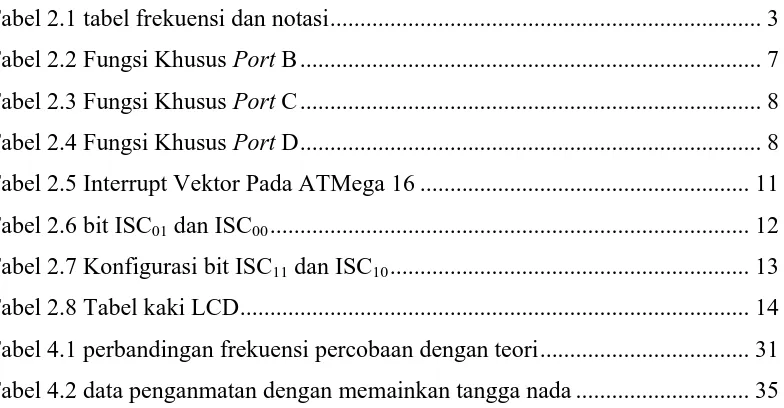
GAMBAR MODUL MIKRO YANG DIGUNAKAN
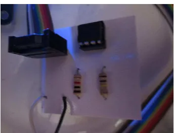
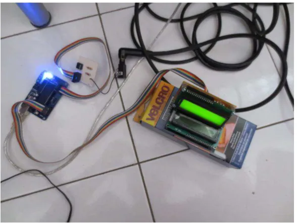
B-2
GAMBAR MODUL LCD
B-3
LAMPIRAN C
SEMICONDUCTOR TECHNICAL DATA
DUAL DIFFERENTIAL INPUT OPERATIONAL AMPLIFIERS
Temperature Range Package
LM2904VD MOTOROLA ANALOG IC DEVICE DATA
Utilizing the circuit designs perfected for recently introduced Quad Operational Amplifiers, these dual operational amplifiers feature 1) low power drain, 2) a common mode input voltage range extending to ground/VEE, 3) single supply or split supply operation and 4) pinouts compatible with the popular MC1558 dual operational amplifier. The LM158 series is equivalent to one–half of an LM124.
These amplifiers have several distinct advantages over standard operational amplifier types in single supply applications. They can operate at supply voltages as low as 3.0 V or as high as 32 V, with quiescent currents about one–fifth of those associated with the MC1741 (on a per amplifier basis). The common mode input range includes the negative supply, thereby eliminating the necessity for external biasing components in many applications. The output voltage range also includes the negative power supply voltage.
• Short Circuit Protected Outputs
• True Differential Input Stage
• Single Supply Operation: 3.0 V to 32 V
• Low Input Bias Currents
• Internally Compensated
• Common Mode Range Extends to Negative Supply
• Single and Split Supply Operation
• Similar Performance to the Popular MC1558
• ESD Clamps on the Inputs Increase Ruggedness of the Device without
Affecting Operation
MAXIMUM RATINGS (TA = +25°C, unless otherwise noted.)
Rating Symbol
LM258 LM358
LM2904 LM2904V Unit
Power Supply Voltages Vdc
Single Supply VCC 32 26
Split Supplies VCC, VEE ±16 ±13
Input Differential Voltage Range (Note 1)
VIDR ±32 ±26 Vdc
Input Common Mode Voltage
Range (Note 2) VICR
–0.3 to 32 –0.3 to 26 Vdc
Output Short Circuit Duration tSC Continuous
Junction Temperature TJ 150 °C
Storage Temperature Range Tstg –55 to +125 °C
Operating Ambient Temperature
Range TA
NOTES: 1. Split Power Supplies.
2. For Supply Voltages less than 32 V for the LM258/358 and 26 V for the LM2904, the absolute maximum input voltage is equal to the supply voltage.
LM358, LM258, LM2904, LM2904V
2 MOTOROLA ANALOG IC DEVICE DATA
ELECTRICAL CHARACTERISTICS (VCC = 5.0 V, VEE = Gnd, TA = 25°C, unless otherwise noted.)
Ch t i ti S b l
LM258 LM358 LM2904 LM2904V
U it Characteristic Symbol Min Typ Max Min Typ Max Min Typ Max Min Typ Max Unit Input Offset Voltage
VCC = 5.0 V to 30 V (26 V for Average Temperature Coefficient of Input
Offset Voltage Average Temperature Coefficient of Input
Offset Current
∆IIO/∆T – 10 – – 10 – – 10 – – 10 – pA/°C
TA = Thigh to Tlow (Note 1) Input Common Mode Voltage Range
(Note 2),VCC = 30 V (26 V for LM2904, V) Large Signal Open Loop Voltage Gain AVOL V/mV
RL = 2.0 kΩ, VCC = 15 V, For Large VO Output Voltage–High Limit (TA = Thigh to
Tlow) (Note 1) VOH
V
Tlow (Note 1)
Output Source Current IO + 20 40 – 20 40 – 20 40 – 20 40 – mA VID = +1.0 V, VCC = 15 V
Output Sink Current IO –
VID = –1.0 V, VCC = 15 V 10 20 – 10 20 – 10 20 – 10 20 – mA VID = –1.0 V, VO = 200 mV 12 50 – 12 50 – – – – – – – µA Output Short Circuit to Ground (Note 3) ISC – 40 60 – 40 60 – 40 60 – 40 60 mA Power Supply Current (TA = Thigh to Tlow)
(Note 1) ICC
2. The input common mode voltage or either input signal voltage should not be allowed to go negative by more than 0.3 V. The upper end of the common mode voltage range is VCC –1.7 V.
3 MOTOROLA ANALOG IC DEVICE DATA
Single Supply Split Supplies
VCC
Representative Schematic Diagram
(One–Half of Circuit Shown)
Output
Bias Circuitry Common to Both
Amplifiers
The LM258 series is made using two internally compensated, two–stage operational amplifiers. The first stage of each consists of differential input devices Q20 and Q18 with input buffer transistors Q21 and Q17 and the differential to single ended converter Q3 and Q4. The first stage performs not only the first stage gain function but also performs the level shifting and transconductance reduction functions. By reducing the transconductance, a smaller compensation capacitor (only 5.0 pF) can be employed, thus saving chip area. The transconductance reduction is accomplished by splitting the collectors of Q20 and Q18. Another feature of this input stage is that the input common mode range can include the negative supply or ground, in single supply operation, without saturating either the input devices or the differential to single–ended converter. The second stage consists of a standard current source load amplifier stage.
Each amplifier is biased from an internal–voltage regulator which has a low temperature coefficient thus giving each amplifier good temperature characteristics as well as excellent power supply rejection.
LM358, LM258, LM2904, LM2904V
4 MOTOROLA ANALOG IC DEVICE DATA
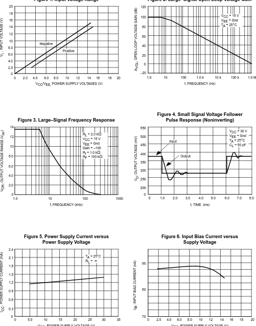
AVOL
, OPEN LOOP
VOL
TAGE GAIN (dB)
VOR
, OUTPUT
VOL
TAGE RANGE (V
)
Figure 1. Input Voltage Range Figure 2. Large–Signal Open Loop Voltage Gain
Figure 3. Large–Signal Frequency Response
Figure 4. Small Signal Voltage Follower Pulse Response (Noninverting)
Figure 5. Power Supply Current versus Power Supply Voltage
Figure 6. Input Bias Current versus Supply Voltage
VCC/VEE, POWER SUPPLY VOLTAGES (V)
120
f, FREQUENCY (Hz)
14
f, FREQUENCY (kHz)
550
VCC, POWER SUPPLY VOLTAGE (V) VCC, POWER SUPPLY VOLTAGE (V)
5 MOTOROLA ANALOG IC DEVICE DATA
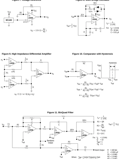
R1
Figure 7. Voltage Reference Figure 8. Wien Bridge Oscillator
Figure 9. High Impedance Differential Amplifier Figure 10. Comparator with Hysteresis
Figure 11. Bi–Quad Filter
MC1403
TBP = Center Frequency Gain TN = Passband Notch Gain
LM358, LM258, LM2904, LM2904V
6 MOTOROLA ANALOG IC DEVICE DATA
2 1
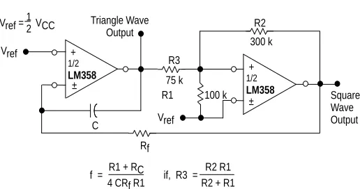
Vref = VCC12
Figure 12. Function Generator Figure 13. Multiple Feedback Bandpass Filter
For less than 10% error from operational amplifier.
If source impedance varies, filter may be preceded with voltage follower buffer to stabilize filter parameters.
Where fo and BW are expressed in Hz.
Qo fo BW < 0.1 Given: fo = center frequency
A(fo) = gain at center frequency
Choose value fo, C
7 MOTOROLA ANALOG IC DEVICE DATA
OUTLINE DIMENSIONS
NOTES:
1. DIMENSION L TO CENTER OF LEAD WHEN FORMED PARALLEL.
2. PACKAGE CONTOUR OPTIONAL (ROUND OR SQUARE CORNERS).
3. DIMENSIONING AND TOLERANCING PER ANSI Y14.5M, 1982.
DIM MIN MAX MIN MAX
INCHES MILLIMETERS
A 9.40 10.16 0.370 0.400
B 6.10 6.60 0.240 0.260
C 3.94 4.45 0.155 0.175
D 0.38 0.51 0.015 0.020
F 1.02 1.78 0.040 0.070
G 2.54 BSC 0.100 BSC
H 0.76 1.27 0.030 0.050
J 0.20 0.30 0.008 0.012
K 2.92 3.43 0.115 0.135
L 7.62 BSC 0.300 BSC
DIM MIN MAX
MILLIMETERS
1. DIMENSIONING AND TOLERANCING PER ASME Y14.5M, 1994.
2. DIMENSIONS ARE IN MILLIMETERS. 3. DIMENSION D AND E DO NOT INCLUDE MOLD
PROTRUSION.
4. MAXIMUM MOLD PROTRUSION 0.15 PER SIDE. 5. DIMENSION B DOES NOT INCLUDE MOLD
LM358, LM258, LM2904, LM2904V
8 MOTOROLA ANALOG IC DEVICE DATA
Motorola reserves the right to make changes without further notice to any products herein. Motorola makes no warranty, representation or guarantee regarding the suitability of its products for any particular purpose, nor does Motorola assume any liability arising out of the application or use of any product or circuit, and specifically disclaims any and all liability, including without limitation consequential or incidental damages. “Typical” parameters which may be provided in Motorola data sheets and/or specifications can and do vary in different applications and actual performance may vary over time. All operating parameters, including “Typicals” must be validated for each customer application by customer’s technical experts. Motorola does not convey any license under its patent rights nor the rights of others. Motorola products are not designed, intended, or authorized for use as components in systems intended for surgical implant into the body, or other applications intended to support or sustain life, or for any other application in which the failure of the Motorola product could create a situation where personal injury or death may occur. Should Buyer purchase or use Motorola products for any such unintended or unauthorized application, Buyer shall indemnify and hold Motorola and its officers, employees, subsidiaries, affiliates, and distributors harmless against all claims, costs, damages, and expenses, and reasonable attorney fees arising out of, directly or indirectly, any claim of personal injury or death associated with such unintended or unauthorized use, even if such claim alleges that Motorola was negligent regarding the design or manufacture of the part. Motorola and are registered trademarks of Motorola, Inc. Motorola, Inc. is an Equal Opportunity/Affirmative Action Employer.
How to reach us:
USA / EUROPE / Locations Not Listed: Motorola Literature Distribution; JAPAN: Nippon Motorola Ltd.; Tatsumi–SPD–JLDC, 6F Seibu–Butsuryu–Center,
P.O. Box 20912; Phoenix, Arizona 85036. 1–800–441–2447 or 602–303–5454 3–14–2 Tatsumi Koto–Ku, Tokyo 135, Japan. 03–81–3521–8315
MFAX: [email protected] – TOUCHTONE 602–244–6609 ASIA/PACIFIC: Motorola Semiconductors H.K. Ltd.; 8B Tai Ping Industrial Park, INTERNET: http://Design–NET.com 51 Ting Kok Road, Tai Po, N.T., Hong Kong. 852–26629298
LM358/D
www.DatasheetCatalog.com
1 Universitas Kristen Maranatha
BAB I
PENDAHULUAN
I.1 Latar Belakang Masalah
Salah satu hal yang terpenting dalam bermusik adalah koordinasi antara para pemain musik tersebut. Komunikasi antara sesama personil sangatlah dibutuhkan untuk membuat permainan musik menjadi bagus. Kadang kala pada saat latihan komunikasi antara pemain musik cukup terhambat dikarenakan pada saat berlatih semua personil memainkan alat musiknya masing-masing, disaat yang bersamaan harus dapat berkomunikasi juga dengan personil pemusik yang lain.
Dalam tugas akhir ini dirancang dan direalisasikan sebuah alat untuk mengubah sinyal audio alat musik gitar bass menjadi Chord yang akan ditampilkan di LCD agar koordinasi antara pemain musik menjadi lebih mudah dan alat tersebut bisa dibawa dengan mudah (portabel).
I.2 Perumusan Masalah
Permasalahan yang akan dibahas dalam tugas akhir ini meliputi :
1. Bagaimana membuat alat pengubah sinyal audio gitar bass menjadi Chord menggunakan Atmega 16 untuk ditampilkan pada LCD.
2. Bagaimana cara menampilkan nada yang dimainkan ke dalam bentuk Chord pada LCD
I.3 Tujuan
Tujuan yang ingin dicapai dari tugas akhir ini bagi mahasiswa adalah :
2 Universitas Kristen Maranatha
I.4 Pembatasan Masalah
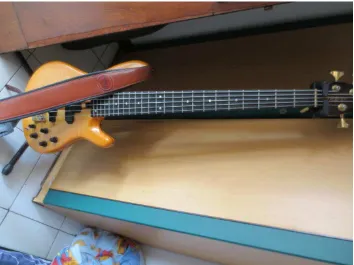
1. Gitar bass digunakan sebagai alat untuk memberkan input sinyal
2. Menggunakan mikrokontroler ATMega16 sebagai pengolah data input menjadi tampilan Chord.
3. Sensor menggunakan piezo.
4. Batas frekuensi pada gitar bass antara 41Hz – 180Hz.
5. Hasil output ditampilkan pada LCD display dalam bentuk Chord. 6. Ketukan tidak ditampilkan pada layar LCD.
7. Pada satu saat hanya 1 frekuensi (nada) yang dibaca mikrokontroler
I.5 SISTEMATIKA PENULISAN
Sistematika penulisan untuk tugas akhir ini adalah sebagai berikut: BAB I. PENDAHULUAN
BAB II. LANDASAN TEORI
BAB III. CARA KERJA DAN KEGUNAANNYA
40
Universitas Kristen Maranatha
BAB V
KESIMPULAN DAN SARAN
Bab ini berisi tentang kesimpulan-kesimpulan yang didapat dari keseluruhan perancangan dan alat untuk menampilkan Chord gitar bass pada LCD dari awal sampai akhir. Lalu bab ini juga berisi saran yang diberikan untuk penelitian lebih lanjut oleh pihak lain.
V.1 Kesimpulan
Dalam merancang dan merealisasikan alat untuk menampilkan Chord gitar bass pada LCD maka dapat disimpulkan :
1. Perancangan dan realisasikan alat yang dapat mengubah sinyal audio gitar bass menjadi Chord yang dapat ditampilkan pada LCD telah berhasil bekerja dengan baik, tetapi mempunyai delay menampilkan 2000ms.
2. Dengan adanya delay 2000ms, alat ini baik digunakan untuk lagu yang memiliki tempo 40-60 bpm(beat per minute).
V.2 Saran
Saran untuk perkembangan alat ini ke depannya adalah sebagai berikut :
1. Menggunakan IC mikro yang dapat merespon input frekuensi secara lebih cepat dan lebih baik juga dapat digunakan untuk alat musik lain selain gitar bass.
41
Universitas Kristen Maranatha
DAFTAR PUSTAKA
1. Andrianto, Heri. 2008. ”Pemrograman Mikrokontroler AVR ATMEGA16 Menggunakan
Bahasa C (CodeVision AVR)”, Bandung: Informatika.
Akses : 4 Agustus 2011
2. file:///C:/Users/Indra/Desktop/Frekuesi-Nada-harmonis-beraturan.htm Akses : 10 November 2012
3. http://electrocontrol.wordpress.com/2011/04/17/penghitung-frekuensi-frequency-counter-menggunakan-codevision-avr/
Akses : 10 November 2012