Modeling of Mobile Robot System with Control Strategy
Based on Type-2 Fuzzy Logic
Siti Nurmaini, Anggina Primanita
Computer Engineering Department, Faculty of Computer Science, Sriwijaya University Jl. Raya Palembang-Prabumulih, Km 32, Inderalaya-Ogan Ilir, Sumatera Selatan, Indonesia
ABSTRACT
This paper describes background knowledge about the mobile robot visualization and their modeling based on the real situations. Software engineering technique is utilized and is extensively applied for modeling a mobile robot system including its interaction with environment. To development mobile robot behaviors, the mobile robot requirement is analyzed, which is expected to wander obstacle avoidance and wall following behavior in unknown environment. This strategy permit a translation from conceptual mobile robot behavior models to computer programming representations and separate concrete control algorithms from mobile robot modeling. Type-2 Fuzzy Logic System (TType-2FLS) is developed to produce control strategy from physical mobile robot. The simulations are conducted in the several indoor environments and implementation of this model is founded satisfactory performance.
Keywords:Mobile robot modeling, type-2 fuzzy logic system, behavior, uncertainty
1.
INTRODUCTION
Controlling a mobile robot to navigate autonomously in real world environments is a challenging and difficult task. Due to there are large amount of uncertainties and imprecisions present in such environments [1-3]. Uncertain environment will give information’s to the sensors and lead to various behavior by the mobile robot. The ability to navigate is obviously a major requirement for a mobile robot to survive in a given environment or to fulfill its mission to reach the goal. The most primitive strategy that might help the mobile robot succeed in navigational tasks consists of relying on mere chance and moving randomly by integrating two concepts: sensing and acting. The demand of sensing and acting concepts in mobile robot applications has motivated researcher to explore the needed intelligence approach to successfully and intelligently perform specific task in specific condition.
Sensing its surroundings, interpreting information of its location in the environment, planning a real-time trajectory, and controlling direction and speed to reach the target are the capabilities of the mobile robot [3]. However, in unknown environment is difficult to implement if not impossible to obtain a precise mathematical model of the mobile robot interaction with its environment [4]. Even if the dynamics of the mobile robot itself can be described analytically, the environment and its interaction with the mobile robot through sensors and actuators are difficult to capture in a mathematical model [2,5]. The lack of precise and complete knowledge about the environment limits the applicability of conventional control system design to the domain of autonomous mobile robot. What is needed are intelligent control and decision making systems with the ability to reason under uncertainty and to learn from experience.
For instance, many studies have done in mobile robot application with uncertain problem such as, fuzzy logic, neural network and evolutionary algorithm [6]. Fuzzy logic system (FLS) has the ability of handling unpredictable and uncertainty problem [5,7,8]. In the robotics research, FLS is a control system that able to navigate mobile robot autonomously without human intervention. By using the FLS rules, mobile robot depend on system’s behavior [7]. The behavior-based approach with fuzzy logic system aims at developing intelligent agent architectures, as well as effective control structures to control agents or physical robots. Because of high flexibility and reactive speed to unstructured environment, robustness and reliability of the system, and powerful capability of extending and learning, this approach has been applied commonly in robotic research [8-11]. However, as a system, mobile robot behaviors is treated as a whole system and modeled in an aggregated level. Therefore an efficient algorithm which is separated from the mobile robot modeling is needed, due to the mobile robot and its behavior is interactive parts of the whole system. The systematical modeling method is highly possible to apply it to robotic research fields.
The widely uses fuzzy logic technique with behavior-based approach in mobile robot applications is the type-1 fuzzy logic system (T1FLS). However, in its implementation, T1FLS has one restriction. The restriction is that its fuzzy set is certain in the sense that the membership grade for each input is a crisp value [12]. It means that it is, in a certain degree, only maps a crisp value into another crisp value ranging from 0 to 1, omitting the uncertainty properties that is initially offered as benefit of fuzzy logic. The loss of uncertainty properties leads to the failure performance of handling uncertainties [13-14]
limitation. It has implemented to accommodate the problem of uncertainty in mobile robot application, and it indicates good results [16-18]. In general, this technique is concerned with the design of intelligent and robust systems. Its exploit the tolerance for imprecision inherent in many real world problems and get a new methods and challenge for the research of intelligence on mobile robot [2].
This paper presents in detail mobile robot modeling and interactions with the environment. The modeling provides the unreal environment that has similar condition to the physical world for giving the mobile robot information. It needs for achieve good result in mobile robot behavior, to enhance mobile robot movement and improve the performance. In the interest of developing mobile robot controller the effectiveness of T2FLS is utilized. T2FLS control algorithm is expected to produce efficient controller, thus the mobile robot has the ability to overcome the uncertainty and achieve good performance in unknown environment.
2.
MOBILE ROBOT DEVELOPMENT
In this research, the mobile robot is expected to wander in unknown and unstructured environment. In general, there are five major models in the process of mobile robot development: (1) the requirement model, (2) the analysis model, (3) the design model, (4) the implementation model and (5) the test model as shown in Fig. 1. The important task in creating a process design is extracting the requirement, named requirement analysis. The mobile robot designers typically have an abstract idea of what they want as an end result, but do not what software should do. Once the general requirements are gleaned, an analysis of the scope of the development should be determined and clearly stated. This is often called a scope document.
Figure 1. Mobile robot development
Implementation model is the part of the development process, where mobile robot and real world actually programmed; in this stage testing model is an important part. Due to the process ensures that bugs are recognized and as early as possible is corrected. Therefore documentation of the internal design for the purpose of future maintenance and enhancement is needed. The last activity is maintenance to cope with newly discovered problems or new requirements can take far more time than the initial development. It may be necessary to add code that does not fit in the original design to correct an unforeseen mobile robot problem.
3.
MOBILE ROBOT DESIGN
3.1 Mobile Robot and Environmental Model
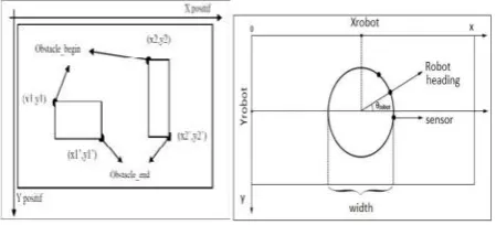
The environmental model is expressed as a two-dimensional area, with x and y axis. The environmental area as a rectangular and bounded by four walls. The scale of environment is 1.4: 1 cm, where 1 cm in the real environment is equal to 1.4 pixels on the application. The boundary of four walls is formed a space of 961 * 561 pixels. Obstacle is created as a two-dimensional rectangle that is placed at a certain point in the environment based on its coordinates. The coordinates location of the rectangulars are determined based on starting point (obst_begin) and end point (obst_end), as shown in Fig. 2(a). The number and location of the obstacles in the environment is static, but it has different sizes.
(a) Environmental design (b) Mobile robot design
Figure 2. Mobile robot model
3.2 Sensor Model
Normally, mobile robot is equipped with various types of sensors in order to guide the robot to achieve its purpose. Location and type of sensors are essential aspects in the mobile robot navigation. Choosing the suitable sensors and sensor placement on the mobile robot in getting the best performance are important case in phase design. Furthermore, the number of sensors installed on the mobile robot also needs to be considered. In this study, mobile robot has 8 ultrasonic sensors that are used for 3 behaviors are obstacle avoidance, wall following, and target seeking.
(a) Sensors placement (b) Sensor transmitter model
Figure 3. Ultrasonic sensor
Fig. 3 shows the location of each sensor. Obstacle avoidance behavior is represented by 3 sensors located in front of the mobile robot, wall following behavior is represented by 4 sensors located in back side of mobile robot, and target seeking is represented by 1 sensor located in backward of mobile robot as shown in Fig 3 (a). Each sensor has a range of rotation to point
o as the mobile robot center. Sensor 2 is at the point Os1 is the reference distance. Placement of sensor 1 (Os0) and sensor 3 (Os2) are at -30
0
and +300 from the center point o. Sensor 5 (Os5) and sensor 7 (Os7) are at -750 and +750 from the point o. While sensor 4 (Os4) and sensor 6 (Os6) are at -1050 and +1050 from the point o. Sensor 8 (Os8) is at the point o as the mobile robot center.
Ultrasonic sensors model is visualized as points in the environment, its movement follows the mobile robot movement, the longest sensor reading is 300 pixels or 214 cm. If the nearest obstacle is more than 300 pixels, the sensor will return a value of 300. Sensor position is obtained by rotating a point based on the angle. In the designed application, sensor readings are based on ideal state, in which sensor model will read distance from nearest obstacle that is placed on the
AOsensorB segment as illustrated on Fig. 3(b). Based on experimental data, the angle AOsensorB of ultrasonic sensor is 400, and the longest distance to obstacle, is illustrated as OsensorA and OsensorB is 300 cm. In this study, sensor reading is obtained by implementing line clipping algorithm [19], to calculate the smallest distance between sensor position, with rectangular obstacle model.
In this study modeling of sensor detection in mobile robot is described as a point on the area as shown in Fig. 4(a). Coordinates of each sensor is determined by calculation of the angle of separation from the mobile robot direction. The sensor has a maximum reading distance (D) and large-span reading (AOsensor B) that will determine the distance between the obstacles with the sensor (J) as depicted in Fig. 4(b).
(a) Distance detection sensor (b) The set of maximum distance
(c) Calculation of the nearest distance
Figure 4. Sensor detection model
As shown in Fig. 4(c), the sensors have a maximum reading distance (D) and large span reading (AOsensor B). Span sensor is described as more than one line from the point of OA. Based on Fig. 4 (a), the calculation of the nearest sensor distance is calculated. If the obstacle (JKLM) is within landscapes (AOsensorB) and smaller than the maximum reading distance (D), then the distance barrier with a sensor which is defined as in equation (1).
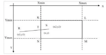
F (distance): J if KLMN < d and JKLM ∈ AOsensor B (1) The results from every sensor readings are obtained from implementing the line clipping algorithm to get the closest distance between the sensor and obstacle. This algorithm uses the tangent line equation to calculate the distance between points to points which intersect with other lines. In Fig. 5, the RS line has a point (x1, x2) and point (y1, y2) as its attributes and obstacle KLMN.
The distance of sensor is translated at the tangent line equation. Point T on the line RS is tangent to the line of
KN can be described by equation (2),
x = x1 + (x2 – x1) * m y = y1 + (y2– y1) * m if, m = 0 then x = x1, y = y1 if, m = 1 then x = x2, y = y2
where, x2 – x1 = dx, y2 – y1 = dy, then:
x = x1 + dx * m (3) y = y1 + dy * m
there are are two conditions,
Xmin ≤ x ≤ Xmax, and (4)
Ymin ≤ y ≤ Ymax
If equation (3) is substituted in equation (4) becomes,
Xmin ≤ x1 + dx * m ≤ Xmax
Ymin ≤ y1 + dy * m ≤ Ymax (5)
Equation (5) can be rewritten as,
- dx * m ≤ x1 – Xmin is left edge condition
dx * m ≤ Xmax – x1 is right edge condition (6) - dy * m ≤ y1 – Ymin is top edge
dy * m ≤ Ymax – y1 is bottom edge
To calculate the gradient line, the equations is obtained from the equation (7)
Pi * m ≤ qi , with i = {1,2,3,4}
m = qi / pi (7)
By entering the value m0 = 0 and m1 = 1, the value of m in equation (7) for each condition is:
if, P < 0 and m > mi Then, mi = m1 (8) if, P > 0 dan m < mi then, mi = m2 (9) i ∈{0,1}.
Furthermore, if equation (7) with conditions is described in equation (8) and (9) produce a general equation of m,
m1 = max ( {qi / Pi | Pi < 0, i=1, 2, 3, 4}, U∈ {0} ) m2 = min ( {qi / Pi | Pi > 0, i =1, 2, 3, 4}, U∈ {1} )
(10) Therefore, the distance that the point T intersection line between the RS line and KN line with the point R which became the starting point of the line is calculated by using Pythagoras equation.
3.3 Goal Point Model
The recognition of certain goal point is used to traverse open areas where no baseboard is visible. The
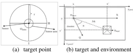
target point on the environment and its location always follow the mobile robot movement. The coordinates of the sensor is equal to the coordinates of the mobile robot because it lies at the center of mobile robot. The function of target sensor is to calculate the distance the mobile robot with the goal point. Shows in Fig. 7 (a), large reading distance from the sensor (r) is adjusted for the large model of the area. The landscape position sensor is a circle with center point Orobot. Large corner one of the 4 pie circle is 900 is characterized by angle HOrobot I.
(a) target point (b) target and environment
Figure 7. Goal point model
The function of position sensor calculates the distance between the target and the distance of rotation as a marker of the direction toward the target. Distance value (Jsk) between the sensor point (Osensor) with the target point (Otarget) and QOsensor Otarget angle (θ) as the distance between the directions of the mobile robot rotation with the target is described in Fig. 7(b). The distance between
Osensor point that have attributes (x, y) and Otarget point that have attributes (x', y') can be calculated uses Pythagoras equation (11).
Jsk = √(x’ - x)2 + (y’ - y) 2 (11)
Direction of the mobile robot is the rotation distance between the point Q and positive X-axis, is marked as angle QOsensorX. The target on the model of the area also has a range of rotation of the X axis is marked with angle
OtargetOsensorX. Hence the mobile robot distance to the direction of the target is calculated by using equation (12).
QOsensorOtarget = QOsensorX - OtargetOsensorX (12) If the angle of QOsensorOtarget is positive, the target at the left side of the mobile robot, if the angle of QOsensorOtarget is negative, the target at the right side of the mobile robot.
4.
TYPE-2 FUZZY LOGIC SYSTEM
DESIGN
behavior is considered as a basic behavior that uses three ultrasonic sensors in front of the mobile robot. The sensor readings provided by the three sensors on the front-right of the mobile robot. In this research, this imprecise value called uncertainty has to be taken into account in order to create a model that is able to tolerate high levels of imprecision in its surroundings.
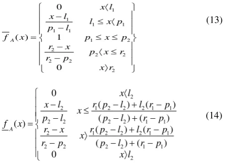
For each input k and rule i, is represented by triangular membership function with uncertain mean. The upper and lower MFs for this interval type-2 fuzzy set can be written in equation (13) and (14) respectively,
Assume that there are N rules in a type-2 fuzzy rule base, each of which has the following form [mendel]:
l
are type-2 fuzzy sets,
and x = (x1, ….., xp) and y are linguistic variables. In this research we used on the type-2 singleton fuzzifier. The inference engine matches the fuzzy singletons with the fuzzy rules in the rule base and provides a mapping from input type-2 fuzzy sets to output type-2 fuzzy sets [12]. The inference engine computes the degree of firing of each rule by using the meet operation [16], between the antecedent membership grades of each rule and the meet operation is implemented by the product t-norm. The firing set is the following type-1 interval set:
Fi(x) = [
f
i(
x
),
f
i(
x
)
]≡
[
f
i,
f
i]
(16)
The firing strength fi of the ith rule is an interval type-1
set determined by its left most point
i
f
and its right
most point
f
i which are calculated as follows: Where * denotes the product t-norm.∏
=The uncertainties in each behavior are modeled in interval type-2 fuzzy sets (T2FS). The input T2FS linguistic variables and their ranges used for obstacle-voidance, are shown in Fig 10 (a) with two outputs which are speed of the motor and steering angle is given in Fig. 10 (b) and 10 (c). It is obvious that the T2FS is in a region constructed by a principal type-1 membership functions (T1MFs). T2FS is obtained by using the fuzzy sets to partition the input domains of the baseline T1FS with footprint of uncertainty (FOU) as shown in Fig.10. Therefore, the T1 membership function is extended to T2MFs by adding FOU in both antecedent and consequent parts of each rule. For all the T2MFs value, the scale 1 pixel is equal to 1.4 cm in real mobile robot data.
(a) Distance as input MFs (b) Speed as output MFs
(c) Steering angle as output MFs
Figure 10 Membership functions
Hence, the MFs is spread values with FOU of the antecedent parts and the consequent parts. From the experiments, three MFs for each input and output are constructed. Fixed values are assigned ranged from 0 to 50 cm for the obstacle distance, 0 to 200 rpm for the speed and 0 to 90 degree for the steering angle depending on the mobile robot action. For output value is the same for the right and left motors.
Table 1. Obstacle Avoidance Behavior Rule
Speed Steering Angle
Before defuzzification process, the outputs is given by inference engine are then processed by the type-reducer, which aggregates the output sets and performs a centroid calculation that leads to T1FSs called the type-reduced fuzzy sets (Hagras, 2004). The calculation of the type-reduced sets is divided into two stages. The first stage is the calculation of centroids of the type-2 interval consequent sets of each rule which is conducted ahead of time. The second stage happens each control cycle to calculate the type-reduced sets which are then defuzzified to produce the crisp outputs (Hagras, 2004). There exist many kinds of type-reduction methods such as centroid, center-of-sets, center-of sums, and height type-reduction. In this research, center of sets type reduction is utilized, where reduced set value is comprises of yl and yr, which is the approach of
inferencing result midpoint. Both of process is calculated in advance and stored in memory. To generate a T1FSs output called Ycos(x) the Karnik-Mendel center-of-sets (cos) iterative algorithm [20] is applied,
[
yl yr]
The output of defuzzification step of FLS is obtained by summing the value of yl and yr obtained from type
reduction step and divide it with two, as shown on equation (20).
�
=
��+�2 � (20)5.
RESULTS AND DISCUSSION
In this paper evaluation is conducted to analyze the mobile robot performance based on T2FLS. The performance compare to T1FLS with different number of rule. The responsiveness of mobile robot movement to avoid obstacle is performed by using simulation. This evaluation is done in three environments, such as open space, complex environment and unstructured walls. The experiments in each environment has its own parameters whose specification is explained later in this section.
The data that needs to be stored in this simulation are the sensor distance, speed and steering angle. All data is obtained from real experiment. In the simulation, each output data is recorded per time unit, which in this case is 1 s. The number of data in each experiment is limited by the number of parameter data to be recorded, or until the mobile robot crashed. In this study, the result is validated through black-box testing. The conclusion of each black box testing based on each model analysis. Furthermore, the analysis of T2FLS mobile robot performance is compared to T1FLS in term of mobile robot trajectory.
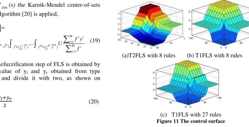
The control surface of the FLS shows in Fig. 11, it represents the performance of FLS in the form of three-dimensional field. There are including the control surface of T2FLS with 8 rules, T1FLS with 8 rules and T1FLS with 27 rules respectively, whose input is distance to the obstacle and output is speed. From Fig. 11 (a) shows that the T2FLS has a smooth surface, is characterized by the number of slopes of the surface, where each slope is portray a gradual change in steering angle. Fig. 11 (b), presents T1FLS with 8 rules, the slopes are steep, showing drastic change of steering angle. The same result with T1FLS with 27 rules, but it is having more slopes than T1FLS with 8 rules as depicted in Fig. 11(c). However, from Fig. 11 (b) and (c) in several points, steering angle value changes is still steep, due to drastic change in mobile robot directions.
(a)T2FLS with 8 rules (b) T1FLS with 8 rules
(c) T1FLS with 27 rules
As result found, T2FLS with 8 rules has smoother surface compare to T1FLS with 8 rules and 27 rules that have steep slopes. Steep slopes on the surface indicates that the velocity change drastically and smoother surface indicates better ability of T2FLS in representing more rules, and gives results gradual changes of speed. It has been noticed in [16], if the number of rules increases for the T1FLS, both its control surface and its performance approaches to T2FLS. Due to the type-2 fuzzy sets contain a large number of embedded type-1 fuzzy sets which allow for a detailed description of the analytical control surface [12].
(a) T2FLS with 8 rules (b) T1FLS with 8 rules
(c) T1FLS with 27 rules (d) Trajectories comparative
Figure 12: Mobile robot trajectories in open space environment
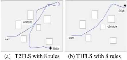
Mobile robot trajectory results from experiment in open space environment as shown in Fig 12. Fig. 12 (a) shows the mobile robot trajectory based on T2FLS in the open space environment, Fig. 12 (b) presents the mobile robot trajectory of the T1FLS with 8 rules and Fig. 12 (c) shows the mobile trajectory of the T1FLS with 27 rules, whereas Fig. 12 (d) describes the graph recorded of the comparative trajectory. As a result found that T2FLS is the first to provide response to the obstacle occurence, follow by T1FLS with 8 rules and T1FLS with 27 rules. The final position of the mobile robot with T2FLS is located farther than two T1FLS.
(a) T2FLS with 8 rules (b) T1FLS with 8 rules
(c) T1FLS with 27 rules (d) Trajectories comparative
Figure 13 Mobile robot trajectories in complex environment
In this simulation, FLS fulfills the requirement of obstacle avoidance behavior that is always keeping the longest distance to the obstacles. Fig. 13 shows mobile robot trajectory to perform obstacle avoidance behavior in complex environment. Initial position of mobile robot is (105,408) with 00 as its initial direction. The number of data recorded is 300 data. Fig. 13 (a), (b), and (c) of T2FLS with 8 rules, T1FLS with 8 rules FLS and T1FLS with 27 rules respectively, whereas Fig. 13 (d) is trajectories comparative. It can be seen that T2FLS with 8 rules always keeps the longest distance from the obstacles and achieves the target. However, T1FLS with 8 rules and 27 rules do not finish the fuzzy process, due to unpredictable situation and environmental uncertainty. Only mobile robot based on T2FLS is able to avoid obstacles while the other is crashed as depicted in Fig. 13(d).
(a) T1FLS with 8 rules (b) T2FLS with 4 rules
(c)T1FLS with 8 rules (d) T2FLS with 4 rules
Figure 14: Mobile robot performances in unstructured walls
Mobile robot to perform wall following behavior is depicted in Fig. 14. In this simulation, the mobile robot distance to the wall is set at ± 22 pixels, equivalent to ± 7.15 cm from right wall. Fig. 14 (b) and (d) shows the graph of simulation in unstructured walls. In this situation, T2FLS with 4 rules gives more stable movement, due to the controller ability to overcome environmental uncertainty. However, T1FLS with 8 rules cannot overcome uncertainties and crashs to the wall as shown in Fig 14(a) and (c).
6.
CONCLUSIONS
desired position taking into account the environmental uncertainty of the mobile robot. Capabilities of the type-2 fuzzy logic system are illustrated by simulations. Based on the evaluation of mobile robot performance, it can be concluded that T2FLS shows more stable performance compare to T1FLS, where there are no sudden changes of steering angle, and showing better responds towards obstacle. In the complex environment shows that T2FLS can overcome environmental uncertainty better than T1FLS with 8 rules and T1FLS with 27 rules, in which both of T1FLS crashed into walls, while T2FLS is able to avoid the obstacles in desired time. Future research topics of interest include the problem of motion control when only displacement measurements are available, and adapting this work to more complex systems such as four-wheeled robot.
REFERENCES
[1] Saffiotti, A. (1997). The uses of fuzzy logic in autonomous robot navigation. Journal Soft Computing, 1(4): 180–197.
[2] Hagras, H. (2007). Type-2 FLCs: a new generation of fuzzy controllers. IEEE Computational Intelligence Magazine, 2(1):30– 43.
[3] Luh, C.C., and Liu, W.W. (2008). An immunological approach to mobile robot navigation. Mobile robots motion planning, New Challenge, in Tech, 291-318
[4] Yang, X., Moallem, M., and Patel, R.V. (2005) A layered goal-oriented fuzzy motion planning strategy for mobile robot navigation. IEEE Trnsc on Systems, Man, and Cybernetics, Part B: Cybernetics, 6, 1214-1224.
[5] Precup, R.E., and Hellendoorn, H. (2010). A survey on industrial applications of fuzzy control.
Computers in Industry, 2239,
[6] Hoffmann, F. (2000). Soft computing techniques for the design of mobile robot behaviors.
Information Science, 122: 241-258.
[7] Seraji, H., and Howard, A. (2002). Behavior-based robot navigation on challenging terrain: A fuzzy logic approach. IEEE Trans. Robotic Automat., 18(3): 308-321.
[8] Maeda M., Maeda, Y., and Murakami, S. (1991). Fuzzy drive control of an autonomous mobile robot, Fuzzy Sets and Systems, (39):195–204.
[9] Aguirre, E., and Gonzalez, A. (2000). Fuzzy behaviors for mobile robot navigation: Design, coordination and fusion. International Journal of Approximate Reasoning, 25 (2000) 255-289
[10] Zhu, A., and Yang, X. S. (2004). A fuzzy logic approach to reactive navigation of behavior-based mobile robots. Proceedings International Conference on Robotics and Automation, New-Orleans, 5045-5050.
[11] Das,T., and Kar, I.N. (2006). Design and implementation of an adaptive fuzzy logic-based controller for wheeled mobile robots, IEEE Trans. Contr. Syst. Technol. (14)3:501–510.
[12] Mendel, J., and John, R. Type-2 Fuzzy Sets Made Simple, IEEE Transactions on Fuzzy Systems, vol. 10, pp.117-127, April 2002.
[13] Sepulveda, R., Melin, P., Rodriguez, A., Mancilla, A., and Montiel, O. (2006). Analyzing the effects of the footprint of uncertainty in type-2 fuzzy logic controllers. Engineering Letters, 13(2):1-12. [14] Zhai, D., and Mendel, J. (2011). Uncertainty
measures for general Type-2 fuzzy sets.
Information Sciences, 181:503–518.
[15] Zadeh, L.A. (1978). Fuzzy sets as a basis for a theory of possibility. Fuzzy Set and System, 1:3– 28.
[16] Hagras, H. (2004). A Hierarchical type-2 fuzzy logic control architecture for autonomous mobile robots. IEEE Transactions on Fuzzy Systems, 12(4):524-539.
[17] Astudillo, L., Castillo, O., and Luis T. (2007). Intelligent control for a perturbed autonomous wheeled mobile robot: a type-2 fuzzy logic approach. Nonlinear Studies, 14(1):37-48.
[18] Baklouti, N. and Alimi, A.M. (2007). Motion planning in dynamic and unknown environment using an interval type-2 TSK fuzzy logic controller. Proceeding of IEEE, 35-40
[19] Liang, Y.D., and Barsky, B. (1984). A new concept and method for line clipping. ACM Transaction on graphics, 11:276-290.