T-Labs Series in Telecommunication Services
Series Editors
Sebastian Möller, Axel Küpper and Alexander Raake
Juliane Krämer
Why Cryptography Should Not Rely on Physical
Attack Complexity
Juliane Krämer
Technical University of Berlin, Berlin, Germany
ISSN 2192-2810 e-ISSN 2192-2829
ISBN 978-981-287-786-4 e-ISBN 978-981-287-787-1 DOI 10.1007/978-981-287-787-1
Springer Singapore Heidelberg New York Dordrecht London Library of Congress Control Number: 2015947940
© Springer Science+Business Media Singapore 2015
This work is subject to copyright. All rights are reserved by the Publisher, whether the whole or part of the material is concerned, specifically the rights of translation, reprinting, reuse of illustrations, recitation, broadcasting, reproduction on microfilms or in any other physical way, and transmission or information storage and retrieval, electronic adaptation, computer software, or by similar or dissimilar methodology now known or hereafter developed.
The use of general descriptive names, registered names, trademarks, service marks, etc. in this publication does not imply, even in the absence of a specific statement, that such names are exempt from the relevant protective laws and regulations and therefore free for general use.
The publisher, the authors and the editors are safe to assume that the advice and information in this book are believed to be true and accurate at the date of publication. Neither the publisher nor the authors or the editors give a warranty, express or implied, with respect to the material contained herein or for any errors or omissions that may have been made.
Printed on acid-free paper
Publications Related to this Thesis
The primary results of this work have been presented in the following publications:
Blömer, Gomes da Silva, Günther, Krämer, Seifert: A Practical Second-Order Fault Attack against a Real-World Pairing Implementation . In Proceedings of Fault Tolerance and Diagnosis in Cryptography (FDTC), 2014, Busan, Korea
Krämer, Kasper, Seifert: The Role of Photons in Cryptanalysis . In Proceedings of 19th Asia and South Pacific Design Automation Conference (ASP-DAC), 2014, Singapore
Krämer, Nedospasov, Schlösser, Seifert: Differential Photonic Emission Analysis . In
Proceedings of Constructive Side-Channel Analysis and Secure Design—Fourth International Workshop (COSADE), 2013, Paris, France
Schlösser, Nedospasov, Krämer, Orlic, Seifert: Simple Photonic Emission Analysis of AES . Journal of Cryptographic Engineering, Springer-Verlag
Schlösser, Nedospasov, Krämer, Orlic, Seifert: Simple Photonic Emission Analysis of AES . In Proceedings of Workshop on Cryptographic Hardware and Embedded Systems (CHES), 2012, Leuven, Belgium
Additionally, Juliane Krämer has authored the following publications:
Krämer, Stüber, Kiss: On the Optimality of Differential Fault Analyses on CLEFIA . Cryptology ePrint Archive, Report 2014/572
Krämer: Anwendungen von identit ä tsbasierter Kryptographie . SmartCard Workshop 2014, Darmstadt, Germany
Michéle, Krämer, Seifert: Structure-Based RSA Fault Attacks . In Proceedings of 8th International Conference on Information Security Practice and Experience (ISPEC), 2012, Hangzhou, China
Contents
1 Introduction
1.1 Thesis Statement
1.1.1 Problem Statement
1.1.2 Thesis Contributions
1.2 Structure of the Thesis
2 Mathematical and Cryptological Background
2.1 Elliptic Curves and Bilinear Pairings
2.1.1 Elliptic Curves
2.1.2 Bilinear Pairings
2.2 Cryptographic Algorithms and Protocols
2.2.1 The Advanced Encryption Standard
2.2.2 Identity-Based Cryptography from Pairings
2.3 Side Channel Attacks
2.3.1 Timing Attacks
2.3.2 Power Analysis
2.3.3 Electromagnetic Analysis
2.3.4 Other Side Channels
2.4 Fault Attacks
2.4.1 RSA
2.4.2 Elliptic Curve Cryptography
2.4.3 Symmetric Cryptography
3.1 Photonic Emission
3.1.1 Photonic Emission in CMOS
3.1.2 Detection of Photonic Emission
3.1.3 Applications of Photonic Emission
3.2 Experimental Setups
3.2.1 The Target Devices
3.2.2 Emission Images
3.2.3 Spatial and Temporal Analysis
4 The Photonic Side Channel
4.1 Simple Photonic Emission Analysis
4.1.1 Physical Attack
4.1.2 Cryptanalysis
4.1.3 Countermeasures
4.2 Differential Photonic Emission Analysis
4.2.1 Physical Attack
4.2.2 Cryptanalysis
4.2.3 Countermeasures
5 Higher-Order Fault Attacks Against Pairing Computations
5.1 Experimental Setup
5.1.1 Low-Cost Glitching Platform
5.1.2 Instruction Skips
5.2 Physical Attack
5.2.1 Realization of Higher-Order Fault Attacks
5.3 Cryptanalysis
5.3.1 Modification of in the Eta Pairing
5.3.2 Modification of in the Eta Pairing
5.3.3 Modification of in the Reduced Tate Pairing
5.4 Countermeasures
6 Future Work
6.1 The Photonic Side Channel
6.1.1 Exploring the Full Attack Potential
6.1.2 Developing Countermeasures
6.2 Fault Attacks Against Pairing-Based Cryptography
6.2.1 Exploring the Full Attack Potential
6.2.2 Targeting Cryptographic Protocols
7 Conclusion
7.1 The Photonic Side Channel
7.2 Fault Attacks Against Pairing-Based Cryptography
7.3 Advice for Cryptographers
List of Figures
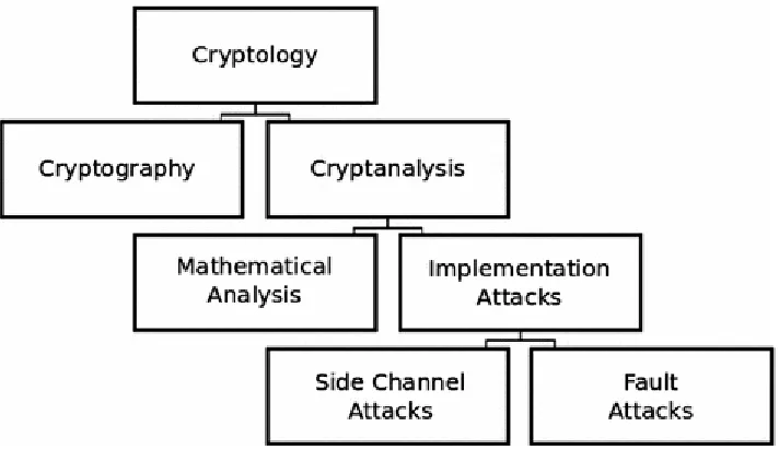
Figure 1.1 The role of implementation attacks in the field of cryptology
Figure 2.1 Point addition of two distinct points on the elliptic curve
Figure 3.1 Photonic emission from a switching CMOS inverter with n-type and p-type transistors (by courtesy of S. Skorobogatov [165])
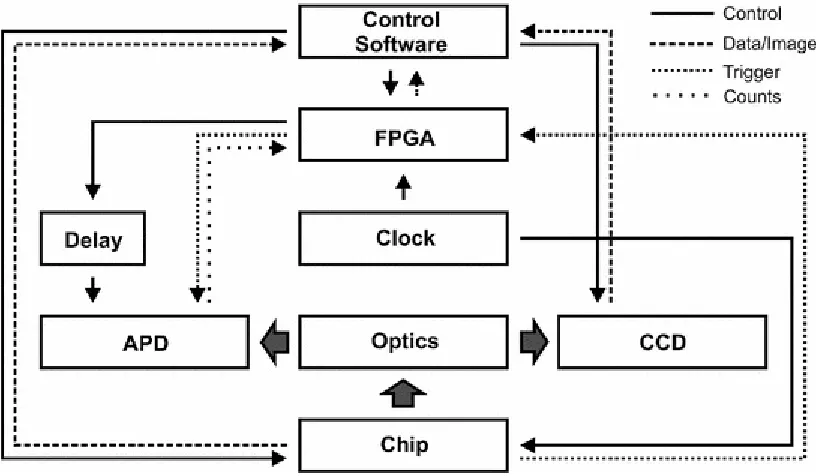
Figure 3.2 The NIR microscope connects the chip under observation to the two detectors (APD and CCD). These are controlled via an FPGA-based controller which handles gate synchronization and delay control as well as time-to-amplitude conversion and multichannel counting
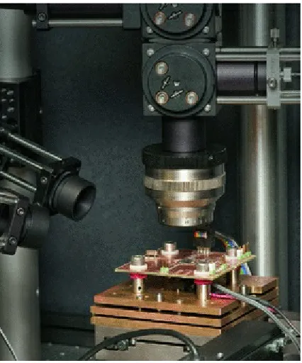
Figure 3.3 In our opto-electronic setup, the chip under observation is mounted upside down on a custom PCB underneath the microscope objective
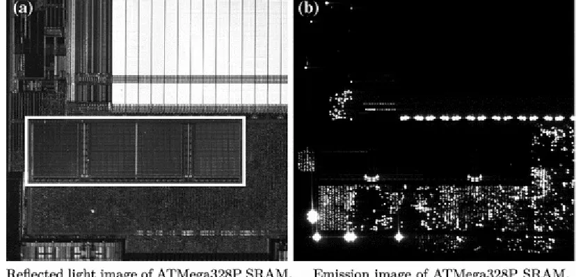
Figure 3.4 Reflected light and 120s emission images of the ATMega328P SRAM with 6.3-fold magnification. The four SRAM banks are marked with a white rectangle in ( a ). The PoC AES implementation is running on the chip
Figure 3.5 Reflected light and 300s emission images of the ATXMega128A1 SRAM with 10-fold magnification. The eight SRAM banks are visible in the top part of ( a ). b shows two highlighted lines in the middle right bank of the upper row . These correspond to accesses to the first two
elements of the AES S-Box. The row driver whose emissions are measured for the SPEA is marked with a red circle
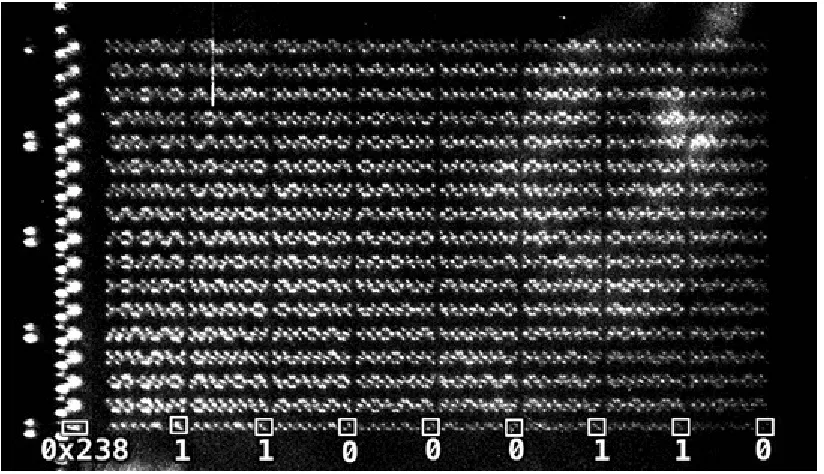
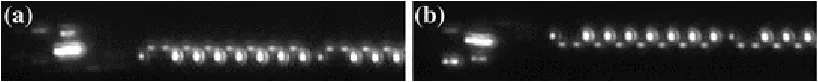
Figure 3.6 Optical emission image of the S-Box in memory. The 256 bytes of the S-Box are located from memory address 0x23f to 0x33e , as in Table 4.1 . The address 0x23f is the eighth byte of the
SRAM line starting with address 0x238 , i.e., the S-Box has an offset of 7 bytes. The emissions of the
row drivers are clearly visible to the left of the memory bank. The image allows direct readout of the bit values of the stored data. The byte shown in the overlay, for example, corresponds to 0b01100011
0x63 , the first value of the AES S-Box
Si-CCD detector. The images were integrated over 120 s. a Access to address 0x300 . b Access to
address 0x308
Figure 4.2 Photonic emission traces of the ATXMega128A1. The observed S-Box row stores only the substitution of the byte 0x00 . The peaks correspond to the 16 AES state bytes. They are clearly
identifiable and show a width of 20 ns, corresponding to the employed detection gate width. The key consists of alternating 0x00 and 0x01 bytes, and so each peak corresponds to 0x00 and 0x01 ,
respectively
Figure 4.3 Photonic emission traces of the ATMega328P. All possible plaintexts were used when accesses to an S-Box row that stores only the substitution of the byte 0x00 were observed. 16 peaks
are clearly identifiable. They correspond to the 16 AES state bytes. Each peak corresponds to a unique key byte, which is annotated
Figure 4.4 Emission images of memory accesses on the ATMega328P. The SRAM line at address
0x300 is clearly visible in ( a ). The highlighted area of ( a ) is shown in greater detail in ( b ). It can
be seen that the driving inverters for the first and second SRAM bank are mirrored
Figure 4.5 Emission images of the driving inverters for the second SRAM bank on the ATMega328P. a shows their bit order. b shows the position and approximate aperture of the measurements
Figure 4.6 Photonic emission traces of the SubBytes operation for a single state byte, captured at the five msb. The three main instructions each take two clock cycles to execute and result in six dominant peaks
Figure 4.7 Result of a DoM analysis for three key bytes. The msb traces were distinguished based on the value of bit 5. The correct key bytes are plotted in red ( dashed ), green ( dotted ), and blue (
dash-dotted ). All other key candidates are plotted in gray
Figure 4.8 Results of a DoM analysis. Relation between the number of pairwise different plaintexts and the achieved min PSR from ten experiments each when 200,000 emission traces were partitioned according to the value of bits 0, 2, 5, or 6
Figure 4.9 DoM analysis with emission traces from a single transistor which corresponds to bit 2. The relation between the number of pairwise different plaintexts and the number of traces per
dash-dotted ), min PSR green ( solid ))
Figure 4.10 Pearson correlation analysis with 200,000 traces per plaintext. Relation between the number of pairwise different plaintexts and the achieved min PSR when the emission traces were analyzed according to the HW of the S-Box input
Figure 4.11 Result of the Pearson correlation analysis of the lsb measurements with different numbers of plaintexts and different numbers of traces per plaintext. The achieved min PSR is depicted (min PSR blue ( dotted ), min PSR red ( dash-dotted ), min PSR green ( solid ))
Figure 4.12 Relation between the number of traces per plaintext and the achieved GSR when the stochastic approach is applied to both sets and combined for 256 plaintexts
Figure 4.13 Relation between the number of pairwise different plaintexts and the achieved GSR when the stochastic approach is applied to both sets and with 200,000 traces per plaintext
Figure 4.14 Comparison between Pearson correlation and DoM for different numbers of plaintexts and different numbers of traces per plaintext
Figure 5.1 Block diagram of the setup for clock glitching. The host configures the glitcher, which generates the glitches on the external clock of the target device, and logs the output from the target device. The target device executes the attacked cryptographic pairing
Figure 5.2 The DDK (glitcher), located on the right , provides the clock ( blue ) and reset signal (
red ) to the target, which is the ATXMega128A1 located in the center. The target also provides back to the DDK the trigger ( green ) indicating the beginning of the computation. The ODROID-U2 board (host), to which both the target’s serial IO ( yellow ) and the DDK’s console are connected to, can be seen on the left . The host configures and monitors the other devices
Figure 5.3 Two different glitches induced by the output gl_clk of the glitcher are shown. The first
glitch is introduced with a delay of cycles of the 33 MHz clock, measured relatively to the trigger gl_trig . Its duration is . With , the 99 MHz clock is directly used to generate
List of Tables
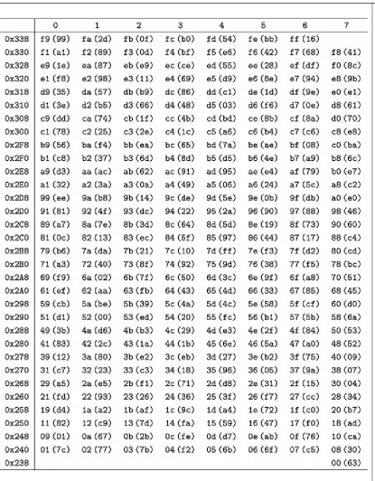
Table 2.1 The AES S-Box, used during the SubBytes operation, in hexadecimal representation
Table 4.1 AES S-Box with 8 bytes per row and an offset of 7
Table 4.2 Example of an SPEA for the first key byte of an AES implementation with an S-Box of width 8 with offset 6
Table 4.3 Example of an SPEA for a single key byte of an AES implementation, given a memory width 8 and an S-Box with odd offset 7
Table 4.4 Number of remaining candidates per key byte and unresolved bits of the full 128-bit key, depending on the offset and row, when each SRAM row stores 8 bytes
Table 4.5 Number of remaining candidates per key byte and unresolved bits of the full 128-bit key, depending on the offset and row, when each SRAM row stores 16 bytes
Table 4.6 Minimal number of unresolved bits of an AES-192 key, depending on the offset and row, when each SRAM row stores 8 bytes
Table 4.7 Minimal number of unresolved bits of an AES-256 key, depending on the offset and row, when each SRAM row stores 8 bytes
Table 4.8 Assembly code of the AES SubBytes Operation
Table 5.1 Assembly code of the end of the for loop, generated with avr-gcc
List of Algorithms
Algorithm 2.1 Miller Algorithm and final exponentiation
Algorithm 2.2 AES-128 Algorithm
Algorithm 5.1 Implementation of on for mod 8, , and E : y2 + y =
x3 + x , as used in our practical fault attack
(1)
© Springer Science+Business Media Singapore 2015
Juliane Krämer, Why Cryptography Should Not Rely on Physical Attack Complexity, T-Labs Series in Telecommunication Services, DOI 10.1007/978-981-287-787-1_1
1. Introduction
Juliane Krämer
1Technical University of Berlin, Berlin, Germany
Juliane Krämer
Email: [email protected]
Cryptanalysis is the art and science of revealing secret information of cryptographic systems. Until approximately 20 years ago, cryptanalysts primarily utilized mathematics to analyze cryptographic schemes. In parallel to the development of more sophisticated ciphers, cryptanalysts were also forced to develop stronger analysis methods. To break the Caesar cipher, which was used 2000 years ago, a simple statistical analysis of a ciphertext was sufficient. The Vigenère cipher was also broken with statistical analysis, albeit in the 19th century. Today’s cryptanalytic attacks are not as simple as a statistical analysis, but involve complex mathematical techniques: differential cryptanalysis, which is mainly applied to block ciphers, analyzes the relation between differences in plaintexts and
differences in ciphertexts [27]. Linear cryptanalysis approximates algorithms and their non-linear operations, respectively, with linear functions to reveal information about the secret key [118]. Related-key attacks study the influence of key-scheduling algorithms on the strength of block
ciphers [26]. These attacks are independent of the number of rounds the block cipher undergoes. Even AES-192 and AES-256 can be weakened with related-key attacks [29].
Despite the existence of these attacks, our current knowledge of mathematics and cryptography allows us to construct secure schemes that can withstand such attacks. The mathematical principles of today’s ciphers are strong enough to securely protect sensitive data, and practical applications of modern ciphers are not threatened by these attacks.
The mathematical strength of an algorithm, however, is only one aspect of the security of a
cryptosystem. The resistance against physical attacks is also an important consideration. These do not target the underlying mathematical principles, but the implementation of the cipher. Consequently, they are also called implementation attacks [98]. In addition to the mathematical cryptanalyses, these implementation attacks nowadays also form part of cryptanalysis and can, in turn, be divided into two groups (see Fig. 1.1, which is based on [135]). The first group measures physical characteristics of the device performing the attacked cryptographic operations, without modifying the computation. These attacks are called passive attacks or side channel attacks. The first published side channel attack analyzed timing variations of several cryptographic algorithms and was published in
1996 [106]. It was shown that a secret exponent from a modular exponentiation, as used in RSA, can be revealed by successively analyzing the timing variations emerging from the value of the exponent bits. For a standard square-and-multiply algorithm, a 1-bit needs more processing steps and is
therefore more time-consuming than a 0-bit. It was also presented how timing variations can reveal information about modular reduction, which in turn reveals information about the size of the
processed values. Interestingly, the underlying principle of side channel attacks was known long before 1996, at least to secret services: in 1952, a covert listening device was found in the Moscow embassy of the United States. It was a replica of the Great Seal of the United States, presented from Soviet youths to the U.S. ambassador in Moscow already in 1946. This device is known as the Thing, or the Great Seal bug. A radio beam was driven at the antenna from a transmitter outside the embassy. The secret information, i.e., the conversations inside the room, was revealed by analyzing the
modulation in the reflected signal emanating from the bug [188]. Thus, with the Great Seal bug, secret information was extracted from physical signals 50 years before Kocher’s pioneering publication. The second group of implementation attacks actively modifies the computation and alters operations by, e.g., randomly changing values [123], changing the sign of a value [32], or skipping
instructions [13]. These effects can be achieved by various mechanisms [17]. Such attacks are called invasive attacks, active attacks, or fault attacks.1 In 1997, the first fault attack was published [38].
The attack targets the RSA signature scheme. It was shown that the RSA modulus can be factorized if an attacker induces a fault into the computation of one of the two parts of the signature generation when the RSA CRT version is used. With a single faulty signature and a correct signature, an attacker can reveal the secret key. The authors only presented the theory, but yet demonstrated the threat that hardware faults might pose to cryptography. Today, publications on both side channel and fault attacks include ideas and describe practical implementations.
Thus, even if the mathematical principles of a certain system are strong enough to protect the system against purely mathematical cryptanalysis, it still might be insecure due to strong
implementation attacks. Even if there are no mathematical weaknesses, side channel attacks or fault attacks might break such a system. Consequently, not only does sensitive information have to be secured with mathematically secure algorithms, but the concrete implementations of these algorithms also have to withstand physical attacks.
Today, it is generally agreed that side channel attacks and fault attacks pose a threat to cryptographic devices and to the secrets that they store. Accordingly, a great deal of research is conducted to find out which side channels can be used [79, 143] and how they can be optimally exploited [93].
Different algorithms are analyzed with respect to their susceptibility towards these attacks [35, 102, 146]. Findings about side channel attack vectors lead to adjustments of the implementations [55] and countermeasures to prevent fault attacks are explored [32, 148]. More sophisticated attacks aim at breaking the improved implementations [10, 71, 110]. The knowledge about side channel attacks has even resulted in a new field of research with the goal to design cryptographic protocols that remain secure even in the presence of leakage from broad classes of side channels [14].
1.1.1 Problem Statement
Knowledge about side channel attacks and fault attacks influences the development of secure devices such as smartcards. Secure hardware vendors put a lot of effort into the development of devices secured against these kinds of attacks. Cryptographic algorithms are not implemented naively, but their implementations are meticulously designed around the knowledge gained from existing attacks.
Cryptographic devices and implementations should be secured against all realistically
conceivable kinds of attacks—but it is difficult to determine which attacks are infeasible and which are not. Attacks which have already been conducted are taken into account, but there are many
potential attack vectors which could be exploited and have not been used yet. In the past these attacks were often considered infeasible because they were believed to be hugely complex and expensive to perform. Thus, implementations lacked the necessary countermeasures to mitigate such attacks.
Unfortunately, when the estimation of the real threat proved wrong afterwards, unprotected devices were in daily use for security applications. The development cycle of cryptographic devices and security applications is too long to react spontaneously to such developments. Vulnerable devices often remain in the field long after they are vulnerable to novel classes of analysis techniques.
Interestingly, in another field of cryptology, the research community does adapt to future threats, although it is yet to be determined whether or not this threat will actually materialize. Quantum computers can invert certain one-way functions upon which the security of several modern
cryptosystems relies [163]. They can solve both the integer factorization problem and the discrete logarithm problem, and thereby destroy the public-key scheme RSA, the Digital Signature Algorithm (DSA), and the Elliptic Curve Digital Signature Algorithm (ECDSA) [24]. Consequently, post-quantum cryptography is already a vibrant field of research, which aims at finding cryptographic schemes which will persist in the presence of quantum computers.
This thesis demonstrates that anticipation of future threats only affects the mathematical strength of cryptographic algorithms, but not their resistance to potential implementation attacks. Since the
potential threat arising from quantum computers by far exceeds the one from yet another implementation attack, the comparison is not ideal. However, overestimating physical attack
complexity is easy to mitigate by implementing more countermeasures against implementation attacks, have they already been realized or not.
1.1.2 Thesis Contributions
We present a side channel attack and a fault attack, both of which were considered unrealistic due to their physical complexity prior to the results demonstrated in this work. These attacks target
First, we present the photonic side channel. This side channel exploits highly spatially resolved photonic emission of the Device Under Attack (DUA) to reveal the secret key of a cryptographic algorithm. It was first presented in 2008, but was not considered a realistic threat due to the immense cost of more than 2,000,000 € for the measurement setup. When we presented a low-cost approach in 2012, we showed that the initial skepticism towards the applicability of this side channel was not justified. Based on this low-cost setup, we developed the theory of Emission Analysis (SPEA) and Differential Photonic Emission Analysis (DPEA) and conducted practical attacks. Given the low-cost system and the methodology of SPEA and DPEA, the photonic side channel complements the
cryptanalytic tools for attacking cryptography.
The second example is a higher-order fault attack against pairing computations. Pairings are the mathematical building blocks of Identity-Based Cryptography (IBC). Ever since they were suggested for this purpose, fault attacks against them were proposed. However, all of these attacks were only described theoretically until we published our results. Not only higher-order attacks, but even single-fault attacks against pairing computations were previously not practically realized. Second-order fault attacks were even considered to be an unrealistic attack scenario [186]. We conducted the first practical fault attack against a pairing computation, and even conducted it against a real-world pairing implementation. We successfully conducted a second-order fault attack against an implementation of the eta pairing from the RELIC toolkit [12], which was also used for the
implementation of Pairing-Based Cryptography (PBC) in Wireless Sensor Networks (WSNs) [131]. By presenting these two examples, we show that reliance upon physical attack complexity is not recommended when it comes to cryptography and the protection of sensitive information. In
mathematics, proven results will always remain true. The human estimation of physical attack complexity, however, is error-prone. We have to face attackers who are better than we expect, and thus, cryptography needs also be secured against presumably physically infeasible attacks.
1.2 Structure of the Thesis
In Chap. 2, we give necessary background information. We provide background on elliptic curves and bilinear pairings and explain the AES algorithm and Identity- Based Encryption (IBE). We present relevant information on side channel attacks and on fault attacks. Then, we present the photonic side channel in Chaps. 3 and 4. These chapters are based on [108, 109, 154, 155]. We explain the physics of photonic emission and the setups that we used for our photonic side channel attacks in Chap. 3. In Chap. 4, we present these attacks: we start with the Simple Photonic Emission Analysis and explain its application on all variants of AES. We also sketch attacks for other
algorithms and discuss countermeasures. The chapter continues with Differential Photonic Emission Analysis. We present our results on AES for different distinguishers and also discuss
countermeasures. The second example of an implementation attack which was assumed to be
unrealistic is the second-order fault attack on pairing-based cryptography. We present our results in Chap. 5. First, we describe the general attack setup that we developed. Then, we explain how we utilized this setup to conduct the attack against the eta pairing. We used the free software
1
Footnotes
(1)
© Springer Science+Business Media Singapore 2015
Juliane Krämer, Why Cryptography Should Not Rely on Physical Attack Complexity, T-Labs Series in Telecommunication Services, DOI 10.1007/978-981-287-787-1_2
2. Mathematical and Cryptological Background
Juliane Krämer
1Technical University of Berlin, Berlin, Germany
Juliane Krämer
Email: [email protected]
First, we provide the necessary mathematical background information on elliptic curves and bilinear pairings. We assume the reader is familiar with abstract algebra and basic probability theory. Next, we present the AES algorithm and introduce Identity-Based Encryption (IBE). The chapter continues with the explanation of side channel attacks and fault attacks. The necessary terminology is presented and related work is discussed.
2.1 Elliptic Curves and Bilinear Pairings
Some of the definitions in this section can also be given more general. However, we wrote this background as concrete as possible. Therefore, the definitions are often customized to our needs and not as universally valid as they are in most text books.
2.1.1 Elliptic Curves
Definition 2.1
(Elliptic Curve) An elliptic curve E over a field K is the set of all points which satisfy the Weierstrass equation
(2.1) together with , the point at infinity. The coefficients are chosen so that the curve is nonsingular, i.e., for all points its partial derivatives do not vanish simultaneously.
An additive group structure can be defined on E. The group , which we refer to as only E,
consists of all points satisfying the Weierstrass equation together with the point at infinity , which is the identity element in E. We denote the additive inverse of with .
(2.2) We denote the group order with . The main result about the group order is Hasse’s theorem.
Theorem 2.1
(Hasse’s theorem) Let E be an elliptic curve defined over a finite field . Then, satisfies
(2.3)
Proof
See [164, p. 138].
Hasse’s theorem only defines boundaries for the cardinality of E. The exact determination of , which is also called point counting problem, is of critical importance for many cryptographic
applications. Methods to solve this problem are discussed in [30].
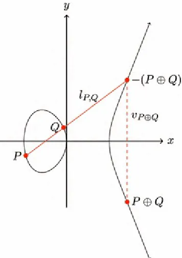
The following explanation of addition and scalar multiplication in E is based on the chord and tangent law [73], since the pairing algorithms deployed in this work make use of this construction.
Fig. 2.1 Point addition of two distinct points on the elliptic curve
Figure 2.1 shows how the sum of two distinct points can be determined. For two points P and Q, the line through P and Q is denoted with . Since the Weierstrass equation is of degree 3 in x, there will always be a third intersection point of and the curve [164]. Assuming that is neither the tangent line at P or Q nor vertical, we denote the third point of intersection with
line with the curve, see Fig. 2.1. This point is the result , the sum of P and Q. Hence,
. In the case that is the tangent of P or Q, the third point of intersection will be P or
Q, respectively. In the case that is vertical, i.e., Q is the reflection of P at the horizontal axis, the third point of intersection is .
To define scalar multiplication, we start with the definition of point doubling. Point doubling is the addition of the point to itself and thus, the procedure is analogous to point addition for two distinct points. To double P and compute , we draw the tangent line through P at E. Since this tangent line intersects E with multiplicity 2 at P, there is only one further intersection point of at E. In the case that the tangent line is not vertical, we denote this third point with and again reflect it at the x-axis to determine the point . The line connecting and is again denoted with . In the case that the tangent line at P is vertical, the third point of intersection at E
is , the point at infinity. Hence, we have in this situation. For the curve which is shown in Fig. 2.1, there are three points with a vertical tangent line. These are (0, 0), , and .
Scalar multiplication of elliptic curve points can now be calculated with successive point additions and point doublings. With , we denote scalar multiplication of P with . For and , we have
(2.4) Consequently, we have
(2.5) and
(2.6) The point representation that is used in this work is referred to as affine coordinate system and affine coordinates. To speed up group operations and to mitigate side channel attacks, points on elliptic curves can also be represented in different coordinate systems such as projective
coordinates [89] and Jacobian coordinates [124].
Definition 2.2
(Torsion Point) Let E be an elliptic curve. For we define the set
(2.7) These points of finite order are called torsion points and is the group of r-torsion points.
Definition 2.3
(Supersingular Curve) Let E be an elliptic curve defined over a field with characteristic p. If for all , E is called supersingular. Otherwise, E is called ordinary.
(Distortion Map) Let E be a supersingular elliptic curve and with . Let so that and P is of exact order r. We call a homomorphism distortion map, if is a basis for and hence, is not in the cyclic subgroup generated by P.
Distortion maps were introduced in [183].
Definition 2.5
(Twist) Let E and be elliptic curves over . If there is an isomorphism defined over with minimal d, then is a degree-d twist of E.
We refer the reader to [30, 31, 54, 104, 164] for a thorough treatment of elliptic curves. Information about elliptic curve cryptography can be found in [30, 31, 54, 89].
2.1.1.1 Elliptic Curve Discrete Logarithm
The Discrete Logarithm Problem (DLP) is a well-known mathematical problem on which
cryptographic algorithms such as ElGamal encryption, the ElGamal signature scheme, and the Diffie-Hellman key establishment are based [119]. The analog problem exists for elliptic curves. It is called Elliptic Curve Discrete Logarithm Problem (ECDLP).
Definition 2.6
(Elliptic Curve Discrete Logarithm Problem) Let E be an elliptic curve over a finite field and so that there is with . The Elliptic Curve Discrete Logarithm Problem
(ECDLP) is, given P and Q, to find n.
As it is the case for the DLP on natural numbers, there are simple instances of the ECDLP, while the problem is not efficiently solvable for other groups and points [30]. For details on elliptic curve discrete logarithms and their application, we refer the reader to [73].
2.1.2 Bilinear Pairings
Bilinear pairings are bilinear maps defined over groups on elliptic curves. Originally, they have been used for cryptanalytic techniques [120]. In 2001, however, they gained the research community’s attention when they were used to realize IBE [39], see Sect. 2.2.2. Today, a wide range of different pairings is used [11] and several cryptographic protocols such as attribute-based encryption [149], identity-based signatures [91], and key agreement protocols [96] are based on pairings. Moreover, pairings help to secure useful technologies such as WSNs [133]. Ever since pairings were proposed to be used for IBE, cryptanalysis of pairings and pairing-based schemes became an active field of research, e.g., [7, 74, 189].
For the definition of pairings, we first have to define the embedding degree.
Definition 2.7
k such that . It satisfies , where denotes the group of rth roots of unity in .
Thus, the embedding degree is the smallest natural number so that has a subgroup of order r, i.e., . Since k is the order of q modulo r, i.e., k is the order of q in the unit group , it follows that k divides Euler’s totient function . Hence, if r is prime, then k divides .
Definition 2.8
(Pairing) Let E be an elliptic curve defined over a finite field . We define three finite abelian groups , , and . The groups and are subgroups of E, while is a subgroup of , with k the embedding degree. A pairing is an efficiently computable, non-degenerate bilinear map
(2.8) We refer the reader to [54] for a thorough treatment of bilinear pairings and their application. For details on the selection of pairing-friendly curves we refer to [72].
Most pairings e(P, Q) on elliptic curves are computed by first computing the so-called Miller function [125] followed by an exponentiation to the power . To understand this Miller function and to study pairings in more detail, we have to address divisors and some of their characteristics.
Definition 2.9
(Divisor) For an elliptic curve E, a divisor D is a formal sum
(2.9) Only finitely many of the coefficients are nonzero. The divisor associated to the point is denoted with .
The divisors generated by the points of E form a free abelian group. We denote the set of all divisors generated by the points of E with Div(E).
We want to define the divisor associated to a rational function. For this definition, we first need to define the order of a rational function at a point of an elliptic curve [164].
Definition 2.10
(Order of a function at a point) Let E be an elliptic curve defined over a finite field , , and . The order of f at P is
(2.10) where denotes the maximal ideal of the local ring .
(2.11) If , we say that f has a zero at P while we say that f has a pole at P if . If
, then f is defined at P and f(P) can be evaluated. Otherwise f has a pole at P and we write .
Definition 2.11
(Divisor associated to a function) Let E be an elliptic curve defined over a finite field , and a nonzero rational function. The divisor associated to f is
(2.12)
A divisor is called principal if it is equal to a divisor that is associated to a function. Thus, is principal if for some nonzero rational function . We say that two divisors are linearly equivalent if is principal. To denote that two divisors are linearly equivalent, we write .
Definition 2.12
(Support of a Divisor) Let E be an elliptic curve and with . The support of D is the set of all points with . Two divisors are coprime when their supports are disjoint.
For a divisor and a principal divisor for some nonzero rational function , we can define the evaluation of f at D if D and are coprime. Then, we define
.
With the help of divisors, we can now define the Miller function, which is the heart of most pairings.
Definition 2.13
(Miller function) Let E be an elliptic curve defined over a finite field . A rational function , with and , is a Miller function if its divisor satisfies
(2.13) The Miller function can also be defined recursively as follows [36, 125]:
The Miller Algorithm successively computes the required function in iterations. Since this algorithm utilizes a for loop, see Lines 2–9, this evaluation is called Miller loop [46]. The value n, which determines the number of loop iterations, is often called Miller bound. The variable f, which is updated during the computation of the for loop until it stores the value of the evaluation of the
Miller function, is called Miller variable.
Independent of the concrete design of a pairing, there are three different types of pairings. Following [75], we distinguish between pairings of Type 1, Type 2, and Type 3. These three basic types differ in the similarity of their domains and .
In a Type 1 pairing, both groups are equal, i.e., .
In a Type 2 pairing, the groups are different, i.e., , but it exists an efficiently computable
homomorphism .
In a Type 3 pairing, the groups are different, i.e., , and there are no efficiently computable homomorphisms between and .
Type 1 pairings are also called symmetric pairings, while Type 2 and Type 3 pairings are called asymmetric pairings. The choice of the type of the pairing is related to the elliptic curve that is used, e.g., Type 1 pairings are generally implemented using supersingular curves over , , and
[158].
Those pairings which are used in cryptography require that their inversion is not efficiently computable. There are four mathematical problems connected to pairing inversion.
Definition 2.14
(FAPI-1) Given a point and a value , both chosen at random, the fixed argument pairing inversion problem (FAPI-1) is to find such that [74].
called FAPI-2.
Both FAPI-1 and FAPI-2 treat the pairing as a black box and only consider the inputs and the output. However, analogous to the two steps of the pairing calculation, i.e., Miller Algorithm and final exponentiation, the pairing inversion can also be treated as a two-step process [100]. Hence, FAPI-1 is usually split into two parts in the literature: the exponentiation inversion [46] and the Miller inversion [74].
Definition 2.15
(Exponentiation Inversion) Given the output of the pairing as well as and the final exponent z, the exponentiation inversion problem is to find the correct preimage of the final exponentiation, i.e., the field element .
Definition 2.16
(Miller Inversion) The Miller inversion problem is, given n, , and a field element , to find the correct input .
Recently, a novel theoretic idea for pairing inversion was presented [100]. Kanayama and Okamoto show that the Miller inversion does not have to be solved in several cases provided that a generic algorithm for solving the exponentiation inversion exists. Thus, given such an algorithm, pairing inversion can be reduced to exponentiation inversion for a special family of pairings, the Ate pairings. This work was later revised and extended [46].
Related to the inversion of pairings, especially when it comes to fault attacks, is the Hidden Root Problem (HRP), which was introduced only in 2008 [181]. We define the HRP exactly as it was defined in the original publication.
Definition 2.17
(Hidden Root Problem) Let be a finite field with elements, where p is prime and let e be a positive integer with . Let be a specified map, i.e., the precise description of which is given, depending on x from a domain to . Let denote an oracle that on input
returns
(2.14) for a fixed secret . The Hidden Root Problem is to recover x in expected polynomial time in
by querying the oracle repeatedly for chosen .
2.1.2.1 The Tate Pairing
We describe the Tate pairing and its reduced variant following [182].
Definition 2.18
(2.15)
Here, and is coprime to .
To yield a unique result instead of a representative of an equivalence class, we define the reduced Tate pairing t.
Definition 2.19
(Reduced Tate Pairing) Let E be an elliptic curve defined over . Let so that r and q are coprime. Let k be the embedding degree. The reduced Tate pairing t is defined as
(2.16)
Thus, the reduced Tate pairing consists of two stages: first the Miller function that is parameterized by P is evaluated at , then a final exponentiation follows to ensure that the algorithm outputs a unique value.
2.1.2.2 The Eta Pairing
The eta pairing can be regarded as an optimized version of the reduced Tate pairing [19, 182]. The optimization consists in a shortened Miller loop. To define the eta pairing, we first need to introduce the Frobenius endomorphism.
Definition 2.20
(Frobenius Endomorphism) Let E be an elliptic curve defined over a finite field . The endomorphism
(2.17) is called Frobenius endomorphism. The group of -rational points on E is fixed by since the qth power is the identity on .
Definition 2.21
(eta Pairing) Let E be a supersingular elliptic curve defined over . Let so that r and q are coprime and let k be the embedding degree. Let n be any integer with so that
and r are coprime. Let be restricted to the Eigenspaces of Frobenius with
and . The eta pairing is defined as
(2.18)
2.2 Cryptographic Algorithms and Protocols
This section first presents the AES algorithm, which is the target of the photonic side channel attacks from Chap. 4. Then, background information on IBC is given.
2.2.1 The Advanced Encryption Standard
The analyses in Chap. 4 focus on the Advanced Encryption Standard (AES). AES is a symmetric encryption algorithm based on the Rijndael cipher [60]. It is ratified as a standard by the National Institute of Standards and Technology of the USA. AES has a fixed block size of 128 input bits and operates on a matrix of bytes, named the state. Depending on the length of the key, which is 128, 192, or 256 bits, the cipher is termed AES-128, AES-192, or AES-256. The algorithm is specified as a number of rounds that transform the input plaintext into the ciphertext. AES consists of 10, 12, and 14 rounds for 128-, 192-, and 256-bit keys, respectively. Each round consists of four operations
SubBytes, ShiftRows, MixColumns, AddRoundKey, except for the final round, which skips the
MixColumns operation. Additionally, there is an initial AddRoundKey operation before the first round. Algorithm 2.2 shows the sequence of the rounds for AES-128.
Regarding AES-128, the initial AddRoundKey operation uses the complete secret 128-bit key. Then, each 128-bit round key is derived deterministically from this original secret key with
Rijndael’s key schedule [60]. During each round of AES-192 and AES-256, also a 128-bit round key is used. The key for the initial AddRoundKey operation consists of the first 128 bits of the secret 192-and 256-bit secret key, respectively. The round key of the first round consists of the remaining bits of the secret key. Regarding AES-192, the second half of this round key is derived with the key
schedule, while for AES-256, the key schedule is used only from the second round.
In the AddRoundKey step, each byte of the state is combined with a byte of the round key using the exclusive or operation ( ). In the SubBytes step, each byte of the state is substituted by an affine transformation of its multiplicative inverse over the Galois field . This is the only operation that provides non-linearity in the algorithm. Since this deterministic operation is very costly, a
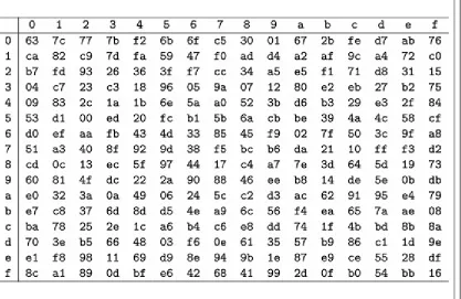
precomputed 8-bit lookup table is often used. This so-called S-Box is shown in Table 2.1. The
deriving the row and column numbers from the byte value. The row number consists of the value of the four Most Significant Bits (msb), i.e., to , and the column number consists of the value of the four Least Significant Bits (lsb), i.e., to . In the ShiftRows step, each row of the state matrix is shifted to the left by 0, 1, 2 or 3 bytes. In the MixColumns step, the four bytes of each column of the state matrix are combined using an invertible linear transformation, resulting in another four bytes.
Table 2.1 The AES S-Box, used during the SubBytes operation, in hexadecimal representation
The 4 msb of the input byte determine the row and the 4 lsb determine the column. The element accessed by the input is the substitution value and hence, the next state value
The memory access patterns of AES are particularly susceptible to cryptanalysis [23, 85, 134]. Optical emissions related to AES S-Box accesses are also exploited in the photonic side channel attacks in Chap. 4. The algorithm running on our Device Under Attack (DUA) consists of a software AES implementation. To increase the frequency of the execution, only the first AddRoundKey and SubBytes operations were computed on the chip after which the input was reset and the measurement restarted. Table 4.8 shows the assembly code of our SubBytes implementation.
2.2.2 Identity-Based Cryptography from Pairings
IBC was invented by Shamir, who presented the idea of this public-key system in 1984 [162]. However, he could not explain back then how to realize such encryption schemes mathematically. Nearly two decades later, in 2001, Boneh and Franklin showed that elliptic curves and pairings can be used to realize IBE [39].
IBE is a form of asymmetric cryptography where the identity of a user is at once his public key. In any form of communication and cryptography, the sender of a message has to know an information about the receiver which is uniquely assigned to him, such as his email address. The idea of IBE is that this information is sufficient to use cryptography and that no further information such as a
manage large numbers of key material.
A system which implements IBE needs a trusted third party or trusted authority, the so-called Private Key Generator (PKG). Following Boneh and Franklin’s initial scheme, four probabilistic polynomial time algorithms are used:
Setup: This algorithm generates all system parameters and the secret master key. Only the PKG knows this master key. The public system parameters include descriptions of the plaintext space
and the ciphertext space and of the set of possible identities.
Extract: The private key of a user is extracted from the secret master key and his identity, i.e., his public key.
Encrypt: The randomized encryption of a message is computed based on the public system parameters and the identity of the receiver, i.e., his public key.
Decrypt: The deterministic decryption function outputs a plaintext for given ciphertext and the receiver’s private key.
In the FullIdent scheme proposed by Boneh and Franklin, both in the Encrypt and Decrypt step a bilinear pairing is computed [39]. During the Decrypt step, the input to the pairing consists of a part of the ciphertext and the secret key of the receiver of that ciphertext. Hence, it has to be ensured that an attacker cannot gain any information about the secret input to a pairing. Attacks on pairings have therefore become a prominent strand within the research on pairings.
An advantage of IBE is the facilitated key management. Certificates are no longer necessary. Furthermore, the sender can send an encrypted message to the receiver even if the receiver does not know his private key yet. It is likewise possible to provide public keys with a validity period which results in a simple method for key revocation. On the other hand, key escrow is immanent in IBE
systems since each private key can be derived from the master key at any time. This is an advantage in the case that each user really trusts the PKG. Otherwise, it is a drawback of such systems. In the case of identity-based signatures, the nonexisting non-repudiation is another disadvantage for the same reason.
Identity-Based Cryptography for Wireless Sensor Networks IBE is especially well suited for those devices with a constrained power supply, such as smartcards and WSNs. On the one hand, WSNs benefit from the non-necessary costly verification of certificates. On the other hand, it is easy to add an additional node since there are no certificates of that node to be verified [50]. Hence, IBE can be used to solve the key distribution problem in WSNs [131]. Another decided advantage is that the existence of a PKG is immanent to WSNs by means of the base station which connects the WSN to other networks. In addition to these advantages, the computation of pairings necessary for IBE is for a given security level more efficient than classical public key cryptography [133]. However, since the PKG can derive all private keys from the master key, in general it is considered a caveat that all users of an IBE system have to trust the PKG.
2.3 Side Channel Attacks
significant research area since the seminal papers of Kocher in 1996 and 1999, which introduced the timing [106] and the power side channel [107]. Since then, a plethora of other side channels,
applications, and analysis methods have been presented. In this section, we provide the necessary background information about side channel attacks and present a selection of relevant work. Side channel attacks are also called passive or non-invasive attacks [35].
The attacker collects a number of so-called traces to reveal the secret information. In the case of power consumption, “a trace refers to a set of power consumption measurements taken across a cryptographic operation” [107]. Thus, each trace consists of a set of side channel leakage values, each related to a distinct point in time. Side channel attacks are divided into univariate and
multivariate attacks. Univariate attacks exploit the leakage of only a single point in time [62], while multivariate attacks exploit multiple aspects of the measurements jointly. Side channel attacks
combining multiple points of leakage are also called higher-order attacks [58, 107]. Since protected implementations can generally not be successfully attacked with a univariate attack, higher-order attacks are also a means to break countermeasures [97, 115].
Since in real-world applications access to the DUA is often restricted, an attacker cannot get an unlimited number of traces. Template attacks compensate for a smaller number of traces during the attack by adding an additional attack phase in which the attacker has unlimited access to an identical experimental device [47]. During this phase, she can execute arbitrary code on this device and
thereby derive templates which model both the signal and the noise. These templates improve the efficiency of the attack in terms of the required number of traces and let the attacker fully utilize the leakage information from each trace.
For the analysis of side channel information, many different distinguishers exist [62, 92].
Distinguishers are the statistical methods which are applied to side channel measurements. However, often the choice of the distinguisher is of minor importance [117].
If a secret key is the target of a side channel attack, it is often not revealed as a whole, but in separate chunks. These separate chunks are called subkeys. If the AES algorithm is the target of the attack, for instance, each key byte is generally revealed independently.
The success rate of an attack can be measured based on its Global Success Rate (GSR) and its Partial Success Rate (PSR). The Global Success Rate is defined as the probability that the complete key is ranked first, i.e., it is the probability of getting the correct value for all key bytes
simultaneously [87]. The Partial Success Rate is defined as the probability that the correct subkey is ranked first among all possible subkeys, i.e., the Partial Success Rate (PSR) is the probability of obtaining the correct value, computed independently for each key byte [92]. Since each key byte has its own PSR, often the minimal PSR (min PSR) is used to describe the attack efficiency [170].
Example 2.1
Assume that we have a set of traces and want to attack a 16-byte key. We randomly choose ten
subsets of the traces and try to reveal the secret key for each of these subsets. In five cases, we reveal the secret key completely, while in the remaining 5 cases, we do not correctly identify the Least
2.3.1 Timing Attacks
In 1996, a timing attack against several cryptographic algorithms was the first published side channel attack [106]. In a timing attack, the attacker analyzes the time required to perform operations which involve secret key material to extract information about that key material. Often, timing attacks target algorithms which employ an exponentiation with a secret exponent, since the timing strongly depends on the value of the processed exponent bits in unprotected implementations [151]. Timing attacks can also be conducted remotely, e.g., against network servers [44].
A variant of timing attacks, both local and remote, are cache attacks. In a cache attack, the timing information provides information about cache hits and misses and hence, about the cache entries. Therefore, cache attacks often target algorithms using table lookups such as AES. In 2004, Bernstein conducted a known-plaintext cache timing attack on the OpenSSL AES implementation that uses
precomputed tables [23]. He extracted a complete 128-bit AES key. The mathematical analysis of our attack presented in Sect. 4.1 is similar to that analysis. In 2005, Percival revealed an OpenSSL 1024-bit RSA private key by exploiting simultaneous multithreading [139]. This OpenSSL implementation used RSA-CRT for private-key operations. During the attack, 310 out of 512 bits per exponent could be extracted, which is enough for factorizing the modulus.
2.3.2 Power Analysis
The second side channel that was exploited is power analysis. In 1999, Kocher et al. presented Simple Power Analysis (SPA) and Differential Power Analysis (DPA). They define SPA as “a technique that involves directly interpreting power consumption measurements collected during
cryptographic operations”. In contrast, DPA does not interpret the traces directly, but uses “statistical functions tailored to the target algorithm” [107]. In this seminal work, the Data Encryption Standard (DES) was attacked. After the publication of these results, countermeasures against power analysis have been developed, e.g., masking and hiding [116]. Masking means to make the processed value uncorrelated to the algorithmic value, while hiding means to make the power consumption
uncorrelated to the processed value. However, the analysis methods also evolved, and higher-order attacks against DPA-resistant software and hardware have been published [53, 121]. A few years ago it was even shown that successful SPAs are still possible, despite several implemented
countermeasures like message padding [57, 110].
Power analysis attacks also target novel algorithms like PBC. In 2006, both SPA and DPA on the eta pairing over binary fields were presented [103]. The authors suggest randomization and blinding as defense against such attacks, both of which are already used in other algorithms such as RSA. In 2009, a DPA against pairing computations was simulated [66]. It was shown how the secret input point to the Miller Algorithm can be revealed by analyzing a modular multiplication and an addition. In 2013, these results were improved and it was theoretically described how the secret input to the Miller Algorithm can be revealed only by a DPA of a modular multiplication [35].
2.3.3 Electromagnetic Analysis
localized measurements allow for side channel attacks which exploit location-dependent information leakage, though to a lesser extent than is the case for Photonic Emission Analysis. The level of
localization is related to the diameter of the magnetic coil usually used in electromagnetic side
channel attacks to acquire the measurements. We refer to Heyszl’s PhD thesis for more information on the strengths and limitations of high-resolution measurements for electromagnetic side channel
attacks [94].
In 2001, two publications on the electromagnetic (EM) side channel appeared [77, 143]. Both publications stress the advantage that EM analysis has over power and timing analysis: exploitation of locally resolved data leakage. A technical description of EM attacks on smartcards is given
in [143]. The authors explain the physics of EM radiation and describe how attacks can be practically realized. However, EM radiation is not analyzed for cryptanalytic purposes in this work. Gandolfi et al. showed by example of a Simple Electromagnetic Analysis (SEMA) against RSA and a
Differential Electromagnetic Analysis (DEMA) against the DES how EM attacks can be practically conducted [77]. Both implementations were unprotected against side channel attacks. The authors state that in terms of their experiments, EM analysis outperforms power analysis. In 2002, Agrawal et al. presented a systematic investigation of the EM side channel for Complementary Metal-Oxide-Semiconductor (CMOS) devices [8]. They present concrete results for two different smartcards. They show that EM analysis can even be successful in the presence of power analysis countermeasures. An extended version of their work is also available [9]. In this work, especially higher order attacks and assessment methodologies for these are examined in more detail.
In 2012, location-dependent electromagnetic leakage was successfully exploited in an attack on an elliptic curve scalar multiplication implementation on a Field Programmable Gate Array (FPGA) using a near-field EM probe [95]. The authors scanned the die surface and collected EM traces at every point. They demonstrated that location-dependent leakage can be used in a template attack and countermeasures against system-wide leakage thus can be circumvented.
2.3.4 Other Side Channels
In addition to these classical side channels, there are also other sources of side channel leakage which can be exploited.
In 2008, a cold boot attack was presented [88]. The authors show how disc encryption keys which are stored in Dynamic Random-Access Memory (DRAM) can be easily stolen if the attacker has physical access to the computer. Contrary to many other side channel attacks, this work assumes a very realistic attack scenario and this attack is a serious security vulnerability. The attack becomes possible since data stored in DRAM does not vanish instantaneously, but fades away gradually when the power is turned off. By cooling the memory, this process can even be slowed down. This attack is considered to be a side channel attack even though the attackers do not capture physical
characteristics of the DUA while it performs computations with secret data. They do, however, exploit the physical implementation of a cryptosystem.
2.4 Fault Attacks
The principle of fault attacks is to disturb the computation of cryptographic operations by induction of one or more faults. From the faulty result, the attacker learns information about the internal sensitive data such as the secret key. The first fault attack against a cryptographic algorithm was presented in 1997 [38]. Since then, fault attacks have been applied against various cryptographic algorithms [180] and became a standard tool to facilitate cryptanalysis. The attack assumptions can be described in detailed fault models, which include the location and the timing of the fault, and the number and kind of faults. Nowadays, many techniques exist to induce faults, e.g., clock glitching, power glitching, and laser beams [17]. To thwart countermeasures against fault attacks, even two faults within one
computation have been performed [102, 177]. These attacks are often called second-order
attacks [63]. More generally, we call a fault attack with more than one fault a higher-order attack.
2.4.1 RSA
The first fault attack against a cryptographic algorithm, known as the Bellcore attack, was presented in 1997 by Boneh, DeMillo and Lipton against the RSA signature scheme [38]. They showed that the RSA modulus can be factorized if an attacker induces a fault into the computation of one of the two parts of the signature generation in case the RSA CRT version is used. With a single faulty signature and a correct signature under the same secret key, an attacker can reveal the secret key.
Since then, RSA has been a popular target for fault attacks. A hardware-based fault attack against the RSA verification process was presented in 2005 [160] and generalized one year later [126]. The attack consists of forcing the attacked cryptographic device to use a slightly modified modulus instead of the original one by inducing transient hardware faults. Since the factorization of the altered
modulus is known, the attacker can calculate a new private key so that the device accepts the
signature of any arbitrary message signed with this new key. A similar attack was presented against the signature process in 2006 [43]. The authors even show how the full RSA private key can be recovered by corrupting the modulus. Hence, it was concluded that “RSA public key elements also have to be protected against fault attacks”. In the same year, it was even questioned if it is wise to publish public key elements [84]. The authors present an attack against the RSA verification process where they induce not transient, put permanent faults. This allows the forgery of any signature at any time.
Another work that targets the RSA modulus was published in 2012 [123]. The authors developed a purely software-based fault attack against the verification process. They showed that the modulus can be completely replaced when the structures which manage the public key material are attacked. The new modulus can be easily factorized with a high probability. The practicability was
demonstrated on a widely deployed conditional access device.
2.4.2 Elliptic Curve Cryptography
not explicitly check whether or not the input point is on the specified curve, a malicious user can just input a point with the desired properties. Later, this work was refined to a more relaxed fault
model [52]. Another idea for fault attacks against ECC are sign change attacks [32], in which the signs of intermediate points are changed to facilitate the computation of the secret scalar. It is more difficult to mitigate these attacks, since the modified points still lie on the original curve, so that integrity checks would not detect the fault after such attacks. Sign change fault attacks were also described against PBC [176]. In 2008, an attack tailored to the Montgomery ladder was
presented [71]. The authors state that they can reveal the secret scalar with only one or two faults, even in the presence of countermeasures which aim at preventing fault attacks. The attacks also consist in performing operations with the modified point on another curve. In this scenario, the modified point lies on the twist of the original curve.
2.4.3 Symmetric Cryptography
Fault attacks were also conducted against symmetric cryptography. Still in 1997, Biham and Shamir described the idea of these kinds of attacks against symmetric cryptographic algorithms [28]. They applied them against the DES and Triple-DES ciphers. Such an attack is called Differential Fault Analysis (DFA), or Differential Fault Attack [140]. The attacker induces faults on the cryptographic primitive level. The assumed fault model gives her partial information about the differences between certain states of the correct and the faulty computations, although she will not know the concrete value of the fault in most scenarios. Since the attacker also knows the correct and faulty ciphertext, and thereby their difference, she can deduce information about the secret key. Small differences in the fault models might crucially affect the capabilities and the complexity of the attacks [28]. Today, there is a wide range of literature on DFA, e.g., [16, 111, 150].
(1)
© Springer Science+Business Media Singapore 2015
Juliane Krämer, Why Cryptography Should Not Rely on Physical Attack Complexity, T-Labs Series in Telecommunication Services, DOI 10.1007/978-981-287-787-1_3
3. Photonic Emission Analysis
Juliane Krämer
1Technical University of Berlin, Berlin, Germany
Juliane Krämer
Email: [email protected]
Low-cost evaluation methods [...] must be considered in security evaluations.
(S. Skorobogatov [165]) Not only S. Skorobogatov called for low-cost evaluation methods. To show that photonic side
channel attacks are a real threat to cryptographic devices, other researchers suggested further research in this direction as well: “An interesting point for future research will be to re-do these experiments on [...] low-cost systems to validate the real benefit of them” [61]. We accomplished this task and showed that successful photonic side channel attacks do not require an awfully expensive measurement system.
The following description is based on [108, 109, 154, 155]. We explain the physical aspects of the photonic side channel in this chapter and continue with the explanation of the cryptographic aspects in Chap. 4. The development of the setups for the measurement of photonic emissions was done by E. Dietz, S. Frohmann, D. Nedospasov, and A. Schlösser.
This chapter is divided into two sections. In Sect. 3.1, we first explain the physical background of photonic emission and detection techniques for their measurement. We review applications of
photonic emissions for failure analysis, cryptography, and reverse engineering. In Sect. 3.2, we
explain in detail the low-cost setups that we used for our photonic side channel attacks. We start with the description of our target devices and then explain the components of the setups and the
methodology for emission images and for spatial and temporal analysis.
3.1 Photonic Emission
Photonic Emission Analysis (PEA) exploits the fact that photonic emissions of a device built in CMOS technology depend on the data it processes and the operations it performs. Contrary to other physical characteristics which depend on the data and the operation, like instantaneous power consumption, however, PEA does not only provide high temporal resolution, but also spatial
orientation and high spatial resolution. The spatial resolution of PEA can go down to transistor level. This allows for more sophisticated and less preventable attacks.
3.1.1 Photonic Emission in CMOS
Photonic emission in silicon has been investigated since the 1950s [51, 129]. First observed in p-n junctions under reverse bias conditions, it was later discovered that Metal-Oxide-Semiconductor Field-Effect Transistors (MOSFETs) exhibit optical emission that is caused by similar effects [112, 172, 174]. Since then, this has been extensively used in IC failure analysis because of the close correlation between the electronic condition of the device and the generated photons.
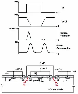
Photons are generated when a transistor switches and current flows. In CMOS technology, photoemission can be observed from a transistor’s channel due to a process called hot-carrier
luminescence. Carriers travelling the conductive channel are accelerated by the electric field between source and drain. At the drain edge of the channel, in the pinch-off region, this energy can be released via phonon-assisted radiative transitions, generating photons [184]. The spectral distribution of the photons follows the energy distribution of the generating electrons, which is spread widely by different effects in the channel. Thus, photon wavelengths reach from the visible to the infrared (IR) with a peak at near-infrared (NIR) wavelengths just above 1 m. Hot-carrier luminescence is a very weak effect: only a tiny amount of electrons contribute to the generation of photons. The photon
generation rate is overproportional to the supply voltage and proportional to the transistor switching frequency. However, the actual emission probability is complex to calculate as many factors
contribute [138]. Scaling, for example, has some positive effects on the emission probability [175], which makes it possible to observe hot-carrier luminescence even in recent technologies.
Fig. 3.1 Photonic emission from a switching CMOS inverter with n-type and p-type transistors (by courtesy of S. Skorobogatov [165])