Plate Girder and Stiffener
(
Gelagar Pelat dan Pengaku
)
Dr. AZ
Introduction
Introduction
(cont’d)Introduction
(cont
’
d)
Introduction
(cont
’
d)
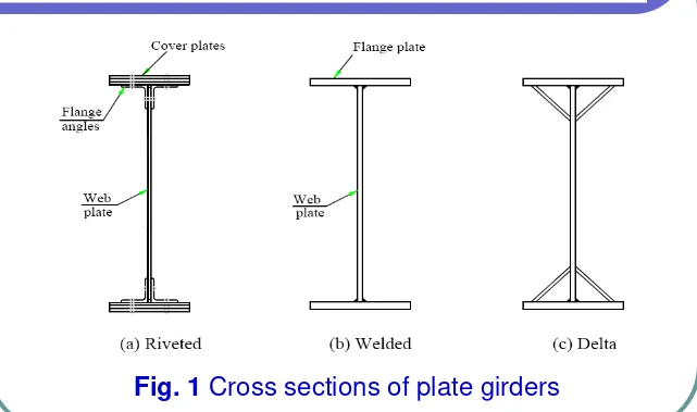
In common, section used for plate girders are shown in
Introduction
(cont
’
d)
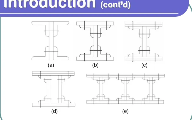
Fig. 2 Common section of plate girders
(a) (b) (c)
Introduction
(cont
’
d)
Introduction
(cont
’
d)
Introduction
(cont
’
d)
Furthermore, the designer has the freedom to use different grades of steel for different parts of the girder. For example, higher-grade steel St. 52 might be used for zones of high applied moments while standard grade steel St. 37 would be used elsewhere. Also, “hybrid
Introduction
(cont
’
d)
Advantages of plate girders:
Easier to fabricate.
Easier to handle in shop.
Bounces not required.
Fewer field splice bolts since bottom flange is narrower than for a box girder.
Lower unit price.
Lighter piece weight erection where crane capacity is a concern.
Advantages of box girders plate girders:
More efficient load distribution due to high torsional
stiffness.
Efficient where girder depth must be minimized.
Efficient for curved alignments.
Less area exposed to airborne road salts.
Less horizontal surface onto which corrosion products
can deposit.
Fewer bearings possible with multiple box girders.
Fewer pieces to erect. Improved aesthetics.
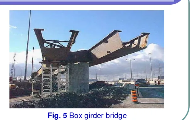
Plate Girders versus Box Girders
Plate Girders versus Box Girders
(cont’d)
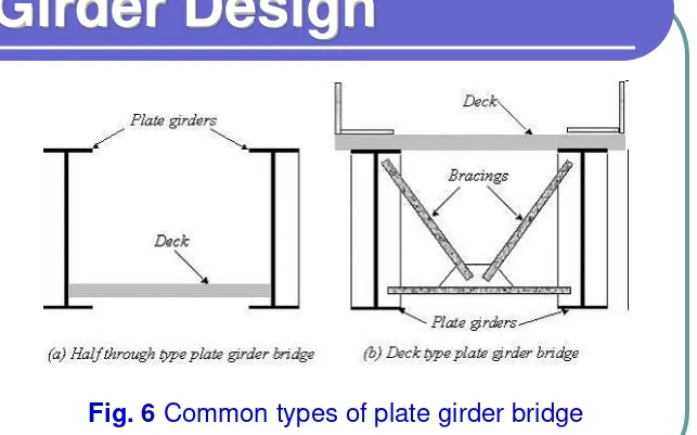
Girder Design
Girder Design
Girder Design
(cont
’
d)
The first step in the design of plate girder section is to select the value of the web depth, D. For railway bridges, the girder depth will usually be in the range Lo/12 to Lo/8, where Lo is the length between points of zero moment. However, for plate girder roadway bridges the range may be extended to approximately Lo/20 for non-composite plate girders and to Lo/25 for composite plate girders. Flange width, 2b: D/4 2b D/3, flange thickness, T:
Girder Design
(cont
’
d)
Having selected the web plate depth, the effective flange area to resist the applied moment, M can be computed from the relation, see Fig. 7(b).
M = FeAehe (Eq. 1)
where:
Fe = allowable bending stress at flange centroid
Ae = equivalent flange area
Girder Design
(cont
’
d)
Girder Design
(cont
’
d)
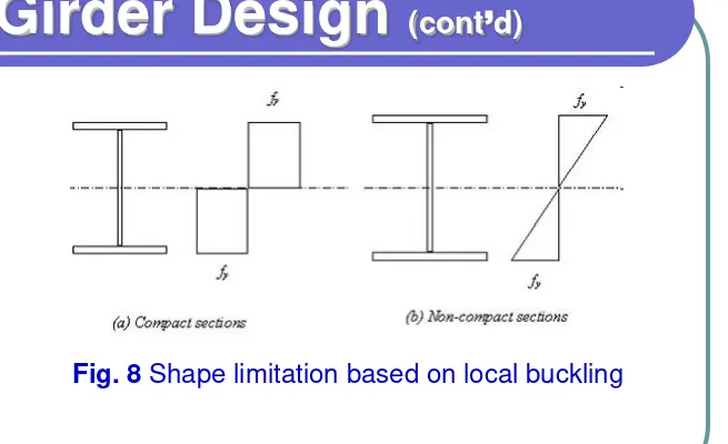
Girders with laterally supported compression flanges can attain their full elastic strength under load, i.e., Fb = 0.64F
y for compact sections and Fb = 0.58Fy for
Girder Design
(cont
’
d)
Girder Design
(cont
’
d)
From Eq. 2, it can be seen that one sixth of the total web area can be considered as effective in resisting moment. Consequently, the area required for each flange will be:
Af = Ae - Aw/6 (Eq. 3) Substituting for Ae from Eq. 1 gives:
Girder Design
(cont
’
d)
An optimum value of the plate girder depth d which results in a minimum weight girder can be obtained as follows:
Express the total girder area as:
Girder Design
(cont
’
d)
Ag is minimum when ∂Ag/∂d = 0 which gives:
d 3 = 1.5β Z
x (Eq. 10)
Substituting Zx = M/Fb, Eq.10 gives:
Girder Design
(cont
’
d)
The value of β will normally lie in the range 100 to 150. With M expressed in meter-ton units and F in t/cm2 units,
the above equation gives the optimum girder depth in meters as:
(Eq. 12) For steel St. 52 with Fb = 0.58Fy this equation gives:
Girder Design
(cont
’
d)
Girder Design
(cont
’
d)
Girder Design
(cont
’
d)
Girder Design
(cont
’
d)
Girder Design
(cont
’
d)
Less than 6tw or more than 4tw
Single Plate
Double Plate Angle