KEY WORDS:Synthetic Aperture Radar (SAR), Ground Control Point (GCP), StereoSAR, interpretation, street objects, simulation
ABSTRACT:
The assignment of phase center positions (in 2D or 3D) derived from SAR data to physical object is challenging for many man-made structures such as buildings or bridges. In contrast, light poles and traffic signs are promising targets for tasks based on 3-D geolocation as they often show a prominent and spatially isolated appearance. For a detailed understanding of the nature of both targets, this paper presents results of a dedicated simulation case study, which is based on ray tracing methods (simulator RaySAR). For the first time, the appearance of the targets is analyzed in 2D (image plane) and 3D space (world coordinates of scene model) and reflecting surfaces are identified for related dominant image pixels. The case studies confirms the crucial impact of spatial resolution in the context of light poles and traffic signs and the appropriateness of light poles as target for 3-D geolocation in case of horizontal ground surfaces beneath.
1. INTRODUCTION
Up to now, the prevalent application areas of spaceborne Syn-thetic Aperture Radar (SAR) are weather and time of day inde-pendent observations of the earth surface. However, several re-cent studies (Schubert et al., 2011) (Eineder et al., 2011) (Schu-bert et al., 2012) (Balss et al., 2014) revealed that SAR offers as well the ability for high precision measurement of absolute po-sitions. In particular, localization accuracy of corner reflectors at the centimeter level is proven for the German SAR satellites TerraSAR-X and TanDEM-X (Balss et al., 2014). This progress in localization accuracy triggers new application scenarios for SAR (e. g. (Runge et al., 2016)) in areas like StereoSAR, geode-tic SAR or absolute ranging. However, the benefit of knowing the absolute phase center position of a point scatterer is heavily dependent on the assignability of the measured position to a real point on a real object. Here, numerical simulations are a valuable instrument to bridge this gap.
2. MOTIVATION AND SCOPE
There is a wide variety of measurement methods for accurate 3-D capture of the environs which can deliver highly accurate relative coordinates but are in need of so-called Ground Control Points (GCPs) with known absolute 3-D coordinates when their results shall be geolocalized with respect to a global reference frame. A frequently used mean to capture precise absolute 3-D coordinates of GCPs are in situ measurements based on the Global Navigation Satellite System (GNSS). But there are many situations where a terrestrial geodetic survey is not practical or even impossible: The journey for the staff may be too costly or the region inaccessible or too dangerous. As soon as a multitude of GCPs is required, in situ survey gets above all very laborious and time consuming.
Therefore, (Balss et al., 2016) proposed a StereoSAR (Chen and Dowman, 2001) (Sansosti, 2004) (Gisinger et al., 2015) (Fratar-cangeli et al., 2016) based remote sensing method to efficiently gather entire networks of 3-D points, to be exploited as GCPs for other sensors like e. g. laser scanners (LiDAR) or stereo cam-eras, without the necessity to enter the region. Prerequisite for
c
Vermessungsbuero cDLR 2014 Patrzek 2015
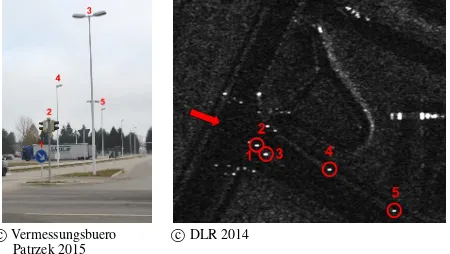
Figure 1. On-site inspection vs. spaceborne SAR; left: photo of a road junction in Oberpfaffenhofen (Germany); right: close-up of this junction in a TerraSAR-X High Resolution Spotlight (HS300) image; a red arrow marks the viewing direction of the
optical image. Some prominent posts (labels 1–5) are likewise identifiable in photo and SAR image.
the extraction of 3-D points by this method and for their transfer as GCPs on the target data is an unambiguous identification of the 3-D points in at least two SAR images acquired from signif-icantly different viewing angle (for extraction) and in the target data (for transfer).
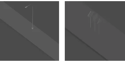
Figure 2. 3D models for SAR simulation.
depends on the radar brightness on the point scatterer relative to its vicinity. As analyzed in (Balss et al., 2016) by cross-check with GNSS reference coordinates, 3-D location accuracy of about 10 cm for lamp poles and less than 30 cm for poles of traffic signs is obtained on base of TerraSAR-X data take.
The optimum would be a sole straight metallic pole without any additions and perpendicularly mounted on a flat asphaltic road surface, as this configuration constitutes a radar reflector which occurs as ideally focused point in a SAR image. There is a dou-ble bounce between the front edge of the pole and the ground. The phase center of the radar echo, which yields the 3-D point, corresponds to the base point of the pole.
However, real poles along roads somewhat differ from this ideal-ized model: The poles carry lamp housings or traffic signs; and a curved design is typical for a frequent type of modern lamp posts (see Fig. 2). Real roads are almost always convex and usually de-clined for drain rain water. If there is a sidewalk along the road, poles are often mounted near the edge of the sidewalk, face away from the road, and the curb constitutes a step between the re-flecting surfaces of sidewalk and road. Any of these effects may cause a small offset between the base point of the pole (which corresponds to the phase center of the bare pole on a flat road surface) and the true phase center position in the real world sce-nario. Thus, understanding the underlying backscatter geometry and evaluating the expected amount of a potential offset between phase center and base point improves the interpretability of the StereoSAR based 3-D points.
Due to the complex shapes of real pole (with mounted additions) and non-flat road surface, numerical simulations are the most ap-propriate mean to investigate the overall effect on the radar sig-nature of the scatterer and to localize the resulting radar phase center relative to the base point of the pole.
This paper presents results of a simulation case study dedicated to light poles and traffic signs in order to better understand the in-herent information in the context of high-resolution SAR images. The simulation method and the case study scenario is described in the following section.
3. INTRODUCTION OF RAYSAR
RaySAR is a 3D SAR simulator (Auer, 2011) developed in a co-operation between DLR and TU Munich (open access on GitHub: see (Auer et al., 2016)). It incorporates an adapted version of the POV-Ray ray tracer (POV-Ray, 2017) and MATLAB tools to gen-erate SAR image layers and analyze the nature of selected scene objects. Besides imagery in the azimuth-range plane (SAR im-age, reflectivity maps, separate layers for reflection levels), 3D
Figure 3. Rendered images of scenario 1 (light pole; left) and scenario 2 (street signs; right) for aspect angle 45◦.
positions of signal phase centers and the extent of signal reflect-ing surfaces can be analyzed. To this end, 3D information is pro-jected into the scene model scene where it is merged with the 3D shape of objects. For the case study below, two object models are under consideration: a curved light pole and standard street signs. In particular, the impact of the following aspects is of interest:
• Post conicity (i.e. diameter change with height)
• Impact of specular and diffuse reflections
• Impact of object curvature (light pole) and surface slopes (road surface)
• Resolution effects for nearby street signs
• Position of prominent signal phase centers
4. SCENARIOS
Two simulation scenarios are defined for covering the aspects of interest above. Scenario 1 concentrates on the imaging of light poles.
• Scene model: curved light pole on pavement, distance be-tween light pole center and pavement border: 1.5 m, road sloped across the heading direction by 3.43◦(6%), 0◦along the road.
• Focus: Simulation of SAR images for different sensor per-spectives; analysis of signal phase center positions.
• Simulation: change of aspect angle: 0◦to 45◦, signal inci-dence angle: 40◦; spatial resolution of SAR image: TerraSAR-X Spotlight, TerraSAR-TerraSAR-X Staring Spotlight.
Scenario 2 is focused on groups of traffic signs:
• Scene model: group of street signs in a row (approx. 6 cm diameter; spatial distance of 0.5 m between the street signs); pavement and road modeling equal to scenario 1. The spa-tial distance between the signs has been selected near the resolution limit of TerraSAR-X.
• Focus: Impact of sensor resolution on the traffic sign ap-pearance.
• Simulation: change of aspect angle: 0◦to 45◦; signal inci-dence angle: 40◦, 49◦, 58◦; spatial resolution: TerraSAR-X HR Spotlight, TerraSAR-X Staring Spotlight.
This contribution has been peer-reviewed. The double-blind peer-review was conducted on the basis of the full paper.
ray tracing) is 1.5 cm at the light pole and 0.25 cm at the street signs.
The following parameters have been used for generating the SAR images:
• High resolution spotlight mode: spatial resolution 1.10 m x 0.59 m (azimuth, range), pixel spacing 0.87 m x 0.46 m (azimuth, range)
• Staring spotlight mode: spatial resolution 0.23 m x 0.59 m (azimuth, range), pixel spacing 0.17 m x 0.46 m (azimuth, range)
• Signal integration: coherent summation of signal contribu-tions for each image pixel
In the remainder of the paper, the high resolution spotlight mode of TerraSAR-X is referred to as ”spotlight mode” (other mode: staring spotlight mode).
5. SIMULATION FOR LIGHT POLE SCENARIO
5.1 Simulation of Images
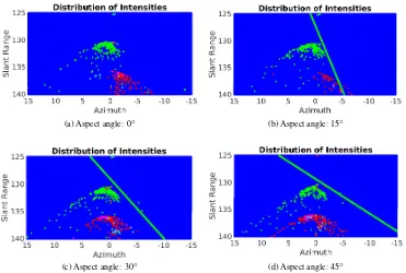
The simulation case study starts with scenario 1 (light pole). As a first step, the spatial distribution of signal contributions is an-alyzed for varying aspect angles (see Fig. 4). It is seen that the allover appearance of the light pole remains comparable. Lo-cal double (and occasional triple reflections) from the lamp head (near range) are followed by an interval of direct backscattering (pole, ground). At the bottom end of the pole, a mix of double reflections (spatially distributed) and point-like triple reflection phase centers with varying positions occur. Finally, higher-order reflection levels end up in far range, again with varying positions for different aspect angles. Ground parts are represented by dif-fuse signal response (direct backscattering). The height step at the pavement border leads to a linear arrangement of double re-flection phase centers (green line) for aspect angles bigger than 0◦.
Fig. 4 shows only the geometric part. Accordingly, it visualizes the geometric composition of signal components in the scene. A look to simulated SAR images based on the signal distribution map adds the radiometric aspect. To this end, the discrete point cloud (signal positions in azimuth, range, elevation) is imposed with a image grid in azimuth and range. Thereafter, the signal intensities are summed coherently for each image pixel.
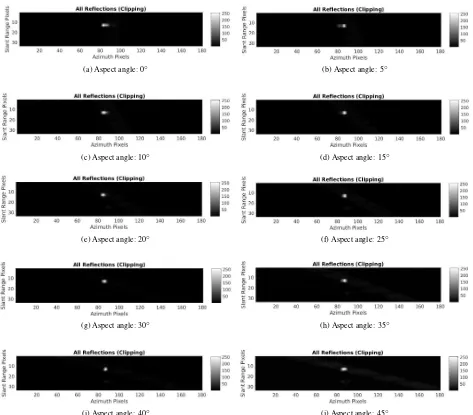
Fig. 5 presents the simulated imagery with the image specifi-cations for TerraSAR-X spotlight mode. It can be seen that the setting of surface parameters (low roughness for surfaces, strong specular behavior for metallic surfaces of the light pole) leads to one dominant point signature, which has a stable position, and a linear signature with varying intensity level for different aspects.
ture) intensity maximum leads to an occasional emphasis of the (ground) intensity. Due to the same reason, the intensity of the double reflection line signature varies (stronger appearance for aspect angles 15◦, 25◦, 35◦, and 45◦). The reason is the impact of the light pole geometry leading to discontinuities for changing perspectives (e.g. pole curvature described with flat polygons).
Also the shape of the point signature appears to change slightly for different aspect angles. To analyze this further, SAR im-ages with higher spatial resolution are simulated. Fig. 6 pro-vides the overview of simulated images with the specifications for TerraSAR-X staring spotlight mode. It is obvious that the shape of the point signature noticeably changes with aspect angle as smearing effects occur in azimuth direction. Likely, the stan-dard double reflection of type ground - pole is mixed with double reflections related to the curved part of the light pole (including lamp head) and the ground.
Interestingly, dominant signatures occur despite the 6%-slope im-posed on the road. This may serve as an indicator that signal contributions related to the road surface are not dominant ones.
5.2 3D Analysis
In this section, the nature of signal phase centers is analyzed for scenario 1 (light pole on pavement). At the beginning, the focus is on the visual impression of simulation results. To this end, one aspect is selected (aspect angle: 45◦, signal incidence angle: 40◦) and the related signal phase centers and relevant ray-surface intersection points are projected back into the 3D model space of the light pole scene. Thereafter, position changes are analyzed for varying aspect angles in order to characterize the perspective-related behavior of prominent phase centers.
RaySAR allows for the interactive selection of pixels of interest in order to generate height profiles and write ray-surface intersec-tion points to a file. Besides, the 3D posiintersec-tions of selected reflec-tion levels (here: signal double reflecreflec-tion) can be projected into the light pole model scene. Results are presented below.
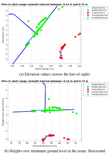
5.2.1 Height Profiles The pixel selection (brightest one) in the SAR image shown in Fig. 5j defines two cross-sections over the image (one in range, one in azimuth) which intersect at the pixel center. The width of the section (perpendicular to the slice direction) is selected as being equal to the TerraSAR-X pixel spacing in azimuth and range, respectively. All signal phase cen-ters within the section are collected, color-coded based on the reflection level, and visualized in a plot. In this context, the ele-vation information (perpendicular to the azimuth and range axes) can be visualized in true elevation (across azimuth and range) or height over ground (relative height with respect to minimum sin-gle reflection contribution in the scene).
(a) Aspect angle: 0◦ (b) Aspect angle: 15◦
(c) Aspect angle: 30◦ (d) Aspect angle: 45◦
Figure 4. Simulated phase center positions for light pole in azimuth and range; blue: single reflection, green: double reflection, red: triple reflection, magenta: fourfold reflection, cyan: fivefold reflection, white: shadow. Unit on axes: meter.
(a) Aspect angle: 0◦ (b) Aspect angle: 5◦ (c) Aspect angle: 10◦ (d) Aspect angle: 15◦ (e) Aspect angle: 20◦
(f) Aspect angle: 25◦ (g) Aspect angle: 30◦ (h) Aspect angle: 35◦ (i) Aspect angle: 40◦ (j) Aspect angle: 45◦
Figure 5. Simulated SAR images for light pole (spotlight mode).
and pavement). Besides, many double reflection phase centers are seen. On the left end, a linear arrangement of double reflec-tion phase centers is related to the corner line between the road and the pavement. Double reflection phase centers near the lower end of the light pole are linked to the signal path ”antenna - light pole - ground - sensor” or ”antenna - ground - light pole - sen-sor” and form a cluster within a elevation interval of approx. 0.6 m. Phase centers of high order (triple to fivefold) relate to signal multiple reflections at light pole parts and the ground and, hence, reveal bigger range values. Phase centers with the same slant range value refer to the same SAR image pixel.
Fig. 7b shows phase center elevation values transformed into heights over ground. Here, the double reflection phase center positions are better comparable to the road level (sloped) and the pavement level (horizontal). It is seen that signal multiple reflec-tions in the scene end up in phase centers approx. 5 m below
the ground level, whereas double reflections mostly remain on the height level of the pavement. Phase center clusters occur at light pole height steps (signal path: ground - light pole base; light pole base - pole) as well as on the pavement surface behind the light pole (origin: signal double reflections including diffuse sig-nal responses from the pavement behind the light pole). Double reflection phase centers below the pavement level occur due to the signal interaction with light pole components and the sloped road.
The simulated height profiles indicate that a visual identification of one dominant phase center (as expected from the simulated SAR image) is not possible. To clarify this, a dedicated analysis on the behavior of cluster centers in the scene is conducted in section 5.2.3.
5.2.2 Projections to Model Space Fig. 8 shows the result of geometric projections into the 3D model space which are
con-This contribution has been peer-reviewed. The double-blind peer-review was conducted on the basis of the full paper.
(c) Aspect angle: 10◦ (d) Aspect angle: 15◦
(e) Aspect angle: 20◦ (f) Aspect angle: 25◦
(g) Aspect angle: 30◦ (h) Aspect angle: 35◦
(i) Aspect angle: 40◦ (j) Aspect angle: 45◦
Figure 6. Simulated SAR images for light pole (staring spotlight mode).
ducted based on the given SAR sensor perspective, the center of the 3D model scene and the simulated phase center distances de-rived from ray tracing. The phase center models (cube with 3 cm side length) have been exported into the Wavefront format (.obj). Besides, the 3D coordinates are stored to a text file (required for analysis shown in Section 5.2.3).
In the context of signal phase centers (see Fig. 8a), the focus is on signal double reflections (other reflection levels contribute too lit-tle intensity to the simulated SAR image to be relevant). Besides the linear arrangement of phase centers (intersection line of road and pavement), different types of double reflection phase centers occur at the surrounding of the light pole. The majority of phase centers are concentrated at the bottom end of the light pole. The surface behind the light pole is covered by phase centers arranged along lines, which are related to signal interaction with the light pole (first signal bounce of specular type) and the ground behind the light pole (second signal bounce of diffuse type). The linear arrangement of the phase centers occurs due to to the representa-tion of the light pole by means of flat polygons and the discrete scene sampling of the ray tracer (for curved light poles the distri-bution of phase centers is expected to be continuous). In the SAR image, the corresponding image signatures are expected to be of
weak intensity and smeared (lack of stability of the reflection ef-fect along the synthetic aperture).
Fig. 8b visualizes all scene surfaces contributing to the most prominent pixel in the SAR image (compare Fig. 5j). To this end, all ray-polygon intersection points contributing to the pixel have been selected and exported to a Wavefront model file (cube size: 3 cm). Surfaces with direct signal response are marked in blue color (pavement, parts of the light pole surface), surfaces con-tributing to signal double reflections are marked in green color. It is seen again that ground and light pole parts contribute to the prominent pixel.
5.2.3 Position of Dominant Phase Centers Fig. 8a visual-izes all phase centers related to signal double reflections. How-ever, only some of them are expected to be of prominent appear-ance (merge of many signal double reflections at a specific posi-tion). This assumption is also supported by the simulated SAR images of the lamp scene (see Figs. 5 and 6), where one salient point signature is obtained for varying sensor perspectives. In this section, prominent phase centers are analyzed for their ap-pearance and position.
(a) Elevation values (across the line-of-sight)
(b) Heights over minimum ground level in the scene. Horizontal pavement, sloped road surface.
Figure 7. Simulated height profiles in range direction based on the selection of the most prominent pixel in the SAR image. The
azimuth interval refers to the pixel size (= TerraSAR-X pixel spacing for spotlight mode).
(a) Phase centers related to signal double reflections, concentrated at the lower end of the
post or spatially distributed at the ground surrounding the post (phase centers represented by cubes of size 3 cm). The linear arrangement of phase centers marks the pavement corner line.
(b) Reflecting surface. Blue: direct response;
Green: double reflection.
Figure 8. Projection of phase centers and reflecting surfaces into the light pole 3D model.
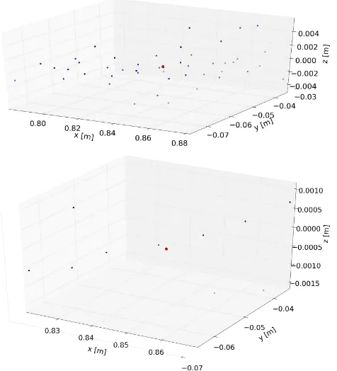
positions in the model world coordinate system. In this context, the world coordinates are stored in a text file in combination with the number of occurrence, which is derived by counting the sim-ulated 3D phase centers in a local neighborhood. In case of the lamp model example, the neighborhood threshold has been set to 1 cm in 3D space. Based on that, dominant phase centers with an occurrence number above a defined threshold are combined for the aspect angles between 0◦and 45◦and analyzed for their spatial spread.
In total, 204k double reflection phase centers occur for all 10
as-Table 1. Summary of phase center geometry and aspect dependence (values rounded to cm). Compare: position of light pole base point at (0.78,0,0). Maximum occurrence level: 174 (=
number of merged signal contributions at one point). dx, dy, dz = intervals on world coordinate axes including all phase center
positions, Asp. = Number of supported aspect angles.
Level x y z dx dy dz Asp.
10 0.79 -0.05 0.00 0.49 0.16 0.08 10 50 0.84 -0.06 0.00 0.10 0.04 0.00 10 100 0.85 -0.05 0.00 0.05 0.03 0.00 7
pects (from 0◦to 45◦with step width 5◦). Setting the occurrence threshold to 50 yields a spatial concentration of phase centers (see top of Fig. 9). Still, phase centers are contributed from all aspects (see last column Table 1). Using the threshold 100, only the most prominent phase centers remain (bottom of Fig. 9), which further stabilizes the position information but leads to no entry for 3 as-pect angles. The height level of the group (at the light pole base point) indicates that the pavement contributes the second surface for the signal double reflection. The mean position of the phase center group is shifted by 8 cm with respect to the light pole base point. This can be explained with signal reflections occurring on the surface of the light pole (diameter varies with height; approx. 8 cm at the bottom end of the light pole). The tilted road surface does not trigger dominant phase centers.
The simulation result does not serve as a proof for light poles being persistent targets. Real scenes are made up of many more objects and characterized by a strong variation of surface prop-erties. However, the simulation confirms for the representative scene set-up that dominant phase centers remain within a spa-tially restricted region for varying aspects. This also contributes to the understanding of one salient point signature in the simu-lated SAR image obtained for all aspect angles. Due to the ge-ometry of the light pole surface, the phase center position cannot remain the same for different aspect angles (nonzero diameter).
6. SIMULATION FOR STREET SIGN SCENARIO
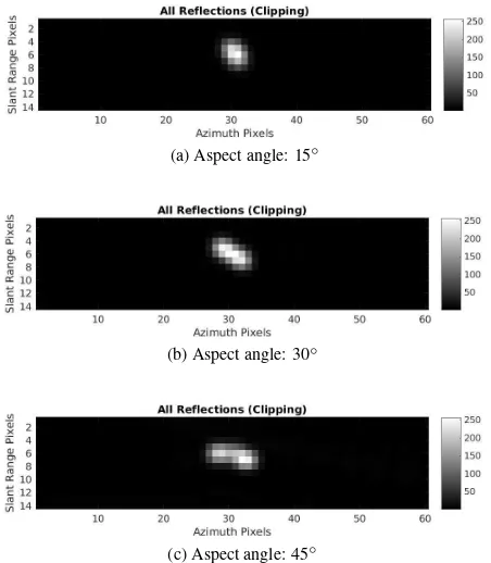
Simulation scenario 2 is concerned with 3 street signs positioned at the equal pavement-road scene with a spatial distance of 0.5 m in between them. The focus of the simulation is on the impact of the sensor resolution on the sign group appearance. Related ef-fects are analyzed for changing aspect angles (0◦, 15◦, 30◦, 45◦) and a signal incidence angle of 40◦. Again, the analysis starts with a view onto the spatial distribution of signal contributions and continues with the visual perception of the simulated SAR images.
Fig. 10 shows the signal distribution for the different aspect an-gles. Imaging effects related to the ground and pavement height step are equal to the light pole example discussed above. Differ-ently, however, the mixture of signal contributions in the center part of the image is now related to the group of traffic signs. From the geometric viewpoint, it is impossible to assign signal com-ponents to the individual signs. Only the shapes of the shadow areas (white color) indicate the presence of three scene objects. This impression is confirmed by the simulated SAR images (see Fig. 11), which have been generated under the assumption of TerraSAR-X spotlight mode. For the aspect angle of 15◦, one point signature is obtained, which appears to be slightly smeared in range direction. For bigger aspect angles, the geometric ar-rangement of the street signs leads to a rotated (for 30◦) and dis-turbed (for 45◦) point signature. Under the assumption of staring
This contribution has been peer-reviewed. The double-blind peer-review was conducted on the basis of the full paper.
Figure 9. Signal double reflection phase centers for occurrence thresholds 50 (contributions from all aspects) and 100
(contributions from 7 aspects).
spotlight mode, these effects become better distinguishable (see Fig. 12). Starting with a dot-like shape for aspect 15◦, the signa-ture is stretched and rotated with an increase of the aspect angle.
7. ADDITIONAL REMARKS
At this point, some additional comments are due:
• Height steps: Height steps participating at signal multiple reflections influence the height level of the phase centers. For the light pole example in the case study, however, domi-nant phase centers were always related to the pavement sur-rounding the light pole. Therefore, the phase center height was equal to the height of the light pole base point.
• Lamp heads: The simulation confirms diffuse signal reflec-tions for the light pole example (no specular ones). How-ever, the corresponding signal strength is weak compared to the dominant signal double reflection of type ”light pole -ground”. Hence, it is expected that prominent lamp head re-sponses require specular direct response or triple reflections. However, this effect is not general for different aspects and, hence, is not stable for varying aspect angles.
• Signal polarization: RaySAR does not cover the simula-tion of signal polarizasimula-tion. Accordingly, assumpsimula-tions in the context of the study are only based on theory. Consider-ing the first signal interaction with the scene, the difference between horizontal and vertical polarization is expected to be small for metallic light poles (weak impact of Brewster angle in vertical polarization) and prominent for horizontal non-metallic surfaces (remarkable impact of Brewster angle for vertical polarization at mid-incidence angles). Accord-ingly, as the dominant phase centers are related to reflections including the horizontal pavement, light pole phase centers
(a) Aspect angle: 15◦
(b) Aspect angle: 30◦
(c) Aspect angle: 45◦
Figure 10. Simulated phase center positions for street signs in azimuth and range; signal incidence angle: 40◦; blue: single
reflection, green: double reflection, red: triple reflection, magenta: fourfold reflection, cyan: fivefold reflection, white:
shadow. Unit on axes: meter.
(a) Aspect angle: 15◦ (b) Aspect angle: 30◦ (c) Aspect angle: 45◦
Figure 11. Simulated SAR images for street signs (spotlight mode) with an signal incidence angle of 40◦.
are expected to be more prominent for the case of horizontal signal polarization (i.e. HH imaging).
8. CONCLUSION
(a) Aspect angle: 15◦
(b) Aspect angle: 30◦
(c) Aspect angle: 45◦
Figure 12. Simulated SAR images for street signs (staring spotlight mode) with an signal incidence angle of 40◦.
and, hence, do not contribute to dominant image signatures. The simulation exemplifies that dominant signal responses may be composed by small phase-center subgroups – located in compact regions – which are merged to one point signature in the related SAR image. The resulting point target (weighted sum of signal components) indicates a spatially compact nature at the intersec-tion between light post and ground surface (variaintersec-tion with aspect depending on light post diameter), which is promising, e. g., in the context of traffic applications.
With regard to StereoSAR applications, where the 2-D localiza-tion informalocaliza-tion from multiple SAR images with different view-ing angle is merged to get 3-D coordinates, a stable phase center position over the entire range of viewing angles in the underly-ing SAR images is a core assumption. However, the case study showed that with varying aspect angle there is a systematic shifts due to the impact of the light pole diameter. The reflecting surface is moving around the pole with aspect. In case of conic poles also the diameter change with height has to be considered. In order to avoid that the attainable accuracy of acquired 3-D coordinates is ruled by the pole diameter, the choice of SAR images with differ-ent elevation angles but similar aspect angles is preferable.
Groups of nearby street signs are merged to point signatures for the high resolution TerraSAR-X imaging modes. The linear ar-rangement of the street signs (case study: 0.5 m spacing between 3 street signs in a row) leads to smearing of the corresponding point signature for side views. Thus, the width of the point signa-ture provides a suitable distinctive criterion when (e. g. in case of the StereoSAR application in view) only point signature from sin-gle objects shall be processed while superposed signatures from nearby objects shall be excluded. Beyond that, only the object shadow areas provides a further hint to several nearby street signs.
Based on the case study, where the focus was on simulation flex-ibility, the next scene setting could be adapted to a real scenario with known target, road and pavement positions / orientations and given TerraSAR-X data.
REFERENCES
Auer, S., 2011. 3D Synthetic Aperture Radar Simulation for Interpreting Complex Urban Reflection Scenarios. PhD thesis, Technische Universit¨at M¨unchen.
Auer, S. and Gernhardt, S., 2014. Linear signatures in urban SAR images – partly misinterpreted? IEEE Geosci. Rem. Sens. Lett. (10), pp. 1762–1766.
Auer, S., Bamler, R. and Reinartz, P., 2016. RaySAR – 3D SAR simulator: Now open source. In:Proceedings of IGARSS confer-ence, pp. 6730–6733.
Balss, U., Gisinger, C., Cong, X. Y., Brcic, R., Hackel, S. and Eineder, M., 2014. Precise measurements of the absolute local-ization accuracy of TerraSAR-X on the base of far-distributed test sites. In: Proceedings of the European Conference on Synthetic Aperture Radar (EUSAR), pp. 993–996.
Balss, U., Runge, H., Suchandt, S. and Cong, X. Y., 2016. Auto-mated extraction of 3-D ground control points from SAR images – an upcoming novel data product. In: Proceedings of IGARSS conference, pp. 5023–5026.
Chen, P. H. and Dowman, I. J., 2001. A weighted least squares solution for space intersection of spaceborne Stereo SAR data. IEEE Trans. Geosci. Remote Sens.39(2), pp. 233–240.
Eineder, M., Minet, C., Steigenberger, P., Cong, X. Y. and Fritz, T., 2011. Imaging geodesy – toward centimeter-level ranging accuracy with TerraSAR-X. IEEE Trans. Geosci. Remote Sens. 49(2), pp. 661–671.
Fratarcangeli, F., Nascetti, A., Capaldo, P., Mazzoni, A. and Crespi, M., 2016. Centimeter COSMO-SkyMed range measure-ments for monotoring ground displacemeasure-ments. Int. Arch. Pho-togramm. Remote Sens. Spatial Inf. Sci.(XLI-B7), pp. 815–820.
Gernhardt, S., Auer, S. and Eder, K., 2014. Persistent scatterers at building facades - evaluation of appearance and localization accuracy.ISPRS J. Photogramm. Remote Sens.100, pp. 92–105.
Gisinger, C., Balss, U., Pail, R., Zhu, X. X., Montaseri, S., Gern-hardt, S. and Eineder, M., 2015. Precise three-dimensional stereo localization of corner reflectors and persistent scatterers with TerraSAR-X.IEEE Trans. Geosci. Remote Sens.53(4), pp. 1782– 1802.
POV-Ray, 2017. POV-Ray. Persistence of Vision Raytracer Pro-priety Limited, www.povray.org [checked: 21.03.2017].
Runge, H., Balss, U., Suchandt, S., Klarner, R. and Cong, X. Y., 2016. DriveMark - generation of high resolution road maps with radar satellites. In:Proceedings of 11th ITS European Congress, pp. 1–6.
Sansosti, E., 2004. A simple and exact solution for the inter-ferometric and Stereo SAR geolocation problem. IEEE Trans. Geosci. Remote Sens.42(8), pp. 1625–1634.
Schubert, A., Jehle, M., Small, D. and Meier, E., 2011. Mitiga-tion of atmospheric perturbaMitiga-tions and solid earth movements in a TerraSAR-X time-series.Journal of Geodesy86, pp. 257–270.
Schubert, A., Small, D., Jehle, M. and Meier, E., 2012. COSMO-SkyMed, TerraSAR-X, and Radarsat-2 geolocation accuracy af-ter compensation for earth-system effects. In: Proceedings of IGARSS conference, pp. 3301–3304.
This contribution has been peer-reviewed. The double-blind peer-review was conducted on the basis of the full paper.