Relay Lab at NTNU
Emil Anthonsen Dyrstad
Master of Energy and Environmental Engineering Supervisor: Hans Kristian Høidalen, ELKRAFT
Department of Electric Power Engineering Submission date: June 2014
Problem Description
Relay protection is essential for reliable operation of power supply. Distributed generation, increased complexity of power systems, and new communication so-lutions require increased focus on protection. Protective relays and their settings are commonly tested in hardware. Simulation results (typically fault currents and voltages) are through an amplifier applied to the actual relay and its re-sponse is verified or settings adjusted. Traditionally only sinusoidal steady-state responses are used, but transients may be of importance. At NTNU there is a plan to expand and build competence in relay protection with a relay lab and a future specialization course. The simple relay protection lab planned at NTNU should include a test bench with distance, over-current and differential relays, and a relay tester for applying simulated waveforms to the relays. A strategic co-operation with Michigan Technological University, Statnett SF and ABB is under establishment and ABB is gifting four Relion 670 relays for transformer, generator and line protection.
The project will consist of:
• Study and document power system protection principles
• Study the different software available to obtain the simulated values
• Develop lab exercise tasks for a future specialization course, with inspiration from a Michigan Technological University
• Design and arrange the practical set-up of the laboratory, including docu-mentation and proposals for future expansions
• Test the preliminary laboratory set-up and create plug-and-play relay con-figuration files to be used in the different lab exercises.
Preface
This report is the result of the authors Master’s thesis at the Department of Elec-tric Power Engineering at the Norwegian University of Science and Technology. The work for the thesis was performed and written in the spring semester of 2014. I would like to express gratitude towards my supervisor, Professor Hans Kris-tian Høidalen, for providing guidance during the semester, and towards Professor Bruce Mork for providing useful input. I would like to thank ABB for their contribution to the relay lab with new and modern protective relays. I am very grateful for the help, guidance and training I have received from Odd Werner-Erichsen at ABB in Västerås, Sweden during the spring of 2014. Siemens Norway also deserves some gratitude on my behalf for letting me participate in their relay seminar for new employees as a third party in October 2013. I would also like to thank Bård Almås, Vladimir Klubicka and Aksel Hanssen for assisting me with the set up of the relay lab.
Notice: Some of the content was included in the authors specialization project report with the same title in the 2013 fall semester. This was deliberate as it functions as pre-project for the Master’s thesis. The content has been edited where deemed necessary.
June, 2014
Trondheim, Norway
Emil Anthonsen Dyrstad
Abstract
This thesis presents background on power system protection, relay principles, modern relay technology and relay testing, to support the design, practical set up and proposals for use of a new relay lab at NTNU.
The paper includes a theoretical part describing the components of power sys-tem protection, their function and attributes. To better the understanding of the importance of power system protection, a short study of the different types of faults that may occur in a power system and how they can be calculated has been made.
One chapter covering the principles of protective relaying functions relevant for the lab, is included. It covers the theory of overcurrent (including directional), distance and differential protection, as well as challenges one may encounter when applying these protective functions.
A chapter on modern relay technology, describing the possibilities and benefits of micro-processor based relays, especially with regards to communication, is a part of the report. This chapter also includes sections describing the inputs and outputs, logic and function of modern relays.
The essentials of relay testing is described in the paper. The different methods available for the testing of relays; scaled physical networks, relay testers and fault simulators are mentioned. Focus has been put on use of relay testers as it is most relevant for the lab. A description of common test procedures is also included. Selected relevant software has been studied to find a software which can be used in the lab exercises.
Discussion of practicalities regarding the lab, i.e. the design and set up of the lab is also made in the thesis. Opportunities for, and use of the lab have been discussed. The basics of relay configuration is explained. Proposals for lab exer-cises that can be performed in the new relay lab are presented near the end.
A list covering proposals for further work for the relay lab is the final part of the thesis.
Sammendrag
Denne rapporten inneholder teoretisk bakgrunn om beskyttelse av kraftsystemer, relévernsfunksjoner, moderne relévernsteknologi og testing av relévern. Den teo-retiske delen støtter det praktiske arbeidet med design, montering og forslag til bruk av en ny relévernlab ved NTNU.
Teoridelen inkluderer beskrivelse av de forskjellige komponentene i ett relévern-system, inkludert deres funksjonalitet og egenskaper. Ett kapittel som forklarer beregninger av kortslutningsstrømmer, er med for å illustrere størrelsen på disse strømmene og viktigheten av relévern.
De mest brukte relévernsprinsippene; overstrøm, distanse og differensial, er beskrevet i rapporten. Utfordringer med bruken av disse er også diskutert. I tillegg er moderne, mikroprosessor-baserte relévern og deres virkemåte forklart. Fordeler med denne teknologien, spesielt med tanke på kommunikasjon, har blitt diskutert.
Forskjellige metoder for reléverntesting er diskutert. Det inkluderer testing i skalerte kraftsystem, testing ved bruk av relétester og bruk av feilsimulator. Pro-gramvare relevant for laben og labøvinger er også beskrevet.
Den praktiske delen av oppgaven, det vil si design og montering av relévern-laben, er en viktig del av rapporten. Dette kapittelet inneholder diskusjon rundt laben, beskrivelse av komponenter, forslag til fremtidige utvidelser og konfig-urering av relévernene. Slutten av rapporten inneholder forslag til labøvinger, samt forslag til videre arbeid.
Contents
1. Introduction 1
2. Power System Protection 2
2.1. Power System Protection Components . . . 2
2.2. Current Transformers . . . 4
2.3. Voltage Transformers . . . 7
2.3.1. Coupling Capacitor Voltage Transformers . . . 7
2.4. Power System Protection Attributes . . . 9
3. Short-Circuits and Abnormal Conditions 13 3.1. Three-Phase(-to-Ground) Faults . . . 14 3.2. Phase-to-Ground Faults . . . 16 3.3. Phase-to-Phase Faults . . . 18 3.4. Double-Phase-to-Ground Faults . . . 19 4. Protection Principles 21 4.1. Fuses . . . 21 4.2. Overcurrent Relay . . . 22
4.3. Directional Overcurrent Relay . . . 24
4.4. Distance Relay . . . 26
4.5. Differential Relay . . . 29
4.5.1. Generator Differential Protection . . . 32
4.5.2. Transformer Differential Protection . . . 32
4.5.3. Busbar Differential Protection . . . 34
5. Modern Relay Technology 35 5.1. Transducer Input and A/D Sampling . . . 36
5.2. Digital Inputs and Outputs . . . 37
5.3. Logic and Function . . . 38
5.4. Communication . . . 39
5.5. IEC61850 - Standard for Design of Substation Automation . . . . 40
5.6. The Future of Relay Technology and Power System Protection . . 41
6. Relay Testing 42 6.1. Testing - Relay Tester . . . 43
6.1.1. Manual Testing . . . 45
6.1.2. Software Routine Testing . . . 47
6.1.3. Event Recording/Simulated Waveform Playback . . . 48
6.2. Testing - Fault Simulator . . . 49
6.3. Testing - Scaled Physical Network . . . 50
6.4. Testing - Summary . . . 52
6.5. Test Procedures . . . 52
7. Software 54 7.1. Short-Circuit Calculation Software . . . 54
7.2. Relay Configuration and Parameter Setting Software . . . 57
8. Relay Lab 60 8.1. Relay Lab at Michigan Technological University . . . 61
8.2. Expansion Steps of Relay Lab . . . 62
8.3. Practical Set Up of Lab . . . 63
8.3.1. Test Switch/Test Handle . . . 67
8.4. Configuration of ABB Relays . . . 69
9. Lab Exercise Proposals 72 9.1. Introduction to Relay Function and Overcurrent Protection . . . . 72
9.2. Distance Protection . . . 75
10.Conclusion 76
11.Further Work 77
A. Appendix - Symmetrical Components 79
B. Appendix - Wide Area Measurement Systems 80
C. Appendix - Connection Diagrams 81
D. Appendix - Equipment List 91
Bibliography 93
List of Figures
2.1. Principles of Power System Protection . . . 2
2.2. Conceptual Illustration of a Current Transformer . . . 4
2.3. Equivalent Circuit for a Current/Voltage Transformer . . . 5
2.4. Excitation Curve for a Multi-Ratio CT[21] . . . 6
2.5. Simplified Equivalent Circuit for Coupling Capacitive Voltage Trans-former with Tuning Inductor . . . 7
2.6. Cross-Section of a Coupling Capacitive Voltage Transformer from Alstom Grid[11] . . . 8
2.7. Protection Zones of a Power System . . . 9
2.8. Example - Relay Coordination for Adjacent Lines - Fault at Line 3 10 3.1. Simple Two Bus Network with Fault on Line . . . 14
3.2. Three-Phase(-to-Ground) Fault . . . 14
3.3. Reduced Sequence Networks Interconnection for Three-Phase Fault. No Negative or Zero Sequence Network Component . . . 15
3.4. Phase-to-Ground Fault . . . 16
3.5. Reduced Sequence Networks Interconnection for Phase-to-Ground Fault . . . 16
3.6. Phase-to-Phase Fault . . . 18
3.7. Reduced Sequence Networks Interconnection for Phase-to-Phase Fault. No Zero Sequence Network Component . . . 18
3.8. Double-Phase-to-Ground Fault . . . 19
3.9. Reduced Sequence Networks Interconnection for Double-Phase-to-Phase Fault . . . 20
4.1. Time-Current Characteristics for a Fuse[19] . . . 21
4.2. Connection of Current Transformers for Overcurrent Relay . . . . 22
4.3. Inverse Time and Instantaneous Characteristics - Overcurrent Protection 23 4.4. Simplified One Line Diagram of Substation with Directional Over-current Relay . . . 24
4.5. Phasor Diagram for Directional Relay using Voltage Reference . . 25
4.6. Distance Relay Principle . . . 26
4.7. Line 1 from Figure 4.6 with Mid-Line Fault . . . 27
4.8. Corresponding RX-diagrams with Zone Settings, Line, Load and Fault Impedances for Line 1 in Figure 4.7 . . . 27
4.9. Protection of Line with Distance Relay at Both Ends of the Line . 28 4.10. Differential Relay Principle . . . 29
4.11. Percentage Differential Relay Current Characteristics . . . 30
4.12. Secondary Current Waveforms with/without CT Saturation . . . 31
5.1. Architecture of Modern Relays . . . 36
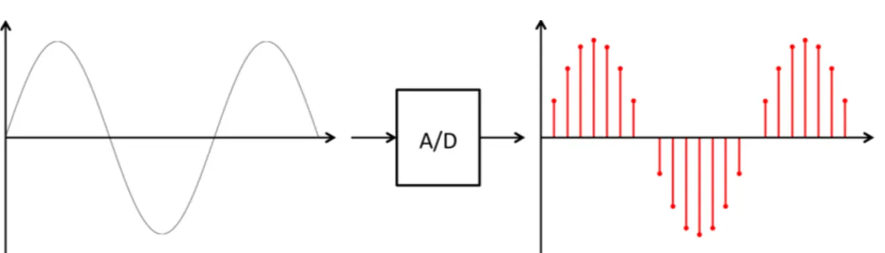
5.2. Sampling of Analog Signal to Digital Values by an Analog to Dig-ital Converter (A/D) . . . 37
5.3. Signal and Function Blocks for Overcurrent Protection in ABB RET670 Relay . . . 38
5.4. IEC61850 Framework - Substation Communication System . . . . 40
6.1. Front Panel of Omicron CMC 356 Relay Tester [23] . . . 43
6.2. Connection Diagram for Three-Phase Testing of Relays using a Relay Tester . . . 44
6.3. Screenshot from Omicron Test Universe 1.61 SR1 - QuickCMC (Control Panel) . . . 45
6.4. Screenshot from Overcurrent Relay Test - Doble F6Test 3.12.0 . . 47
6.5. Screenshot from Differential Relay Test - Omicron Test Universe 1.61 SR1 . . . 48
6.6. Screenshot from Playback of *.pl4-file in Doble Protection Suite 3.0. Displays Currents and Voltages in a Three-Phase System During a Phase-to-Ground Fault . . . 49
6.7. Front Panel of Fault Simulator from Cebec AB . . . 50
6.8. One Line Diagram of SG Lab at NTNU . . . 51
6.9. Pick-up Indication Testing . . . 53
7.1. Screenshot - PCM600 2.6 - ABB Protection and Control IED Man-ager . . . 57
7.2. Screenshot - Signal Matrix - PCM600 2.6 . . . 59
8.1. Conceptual Illustration of Relays in Mobile Rack . . . 63
8.2. Backside of Relay and Test Switch . . . 65
8.3. Relay Power Supply . . . 66
8.4. ABB RTXP24 Test Switch (right) and RTXH24 Test Handle (left)[4] 68 8.5. Contact Functions - ABB RTXP 24 Test Switch/Handle . . . 68
8.6. One Line Diagrams for ABB Relion 670 Relays . . . 71
9.1. Network - Lab Exercise . . . 73
9.2. Screenshot - Plant Structure - PCM600 2.6 . . . 74
A.1. Positive, Negative and Zero Sequence Vectors . . . 79
C.1. Card Slots - ABB Relion 670 (6U 1/2 19") . . . 81
C.2. Connection Diagram - Power Supply Rack 1 . . . 82
C.3. Connection Diagram - Power Supply Rack 2 . . . 82
C.4. Connection Diagram - RED670-1 - Current and Voltage Leads between BOM and Test Switch . . . 83 C.5. Connection Diagram - RED670-2 - Current and Voltage Leads
between BOM and Test Switch . . . 84 C.6. Connection Diagram - RET670 - Current and Voltage Leads between
BOM and Test Switch . . . 85 C.7. Connection Diagram - REG670 - Current and Voltage Leads between
BOM and Test Switch . . . 86 C.8. Connection Diagram - RED670 - Current and Voltage Leads between
TRM and Test Switch[5] . . . 87 C.9. Connection Diagram - RED670 - Current and Voltage Leads between
TRM and Test Switch[5] . . . 88 C.10.Connection Diagram - REG670 - Current and Voltage Leads between
TRM and Test Switch[5] . . . 89 C.11.Connection Diagram - RET670 - Current and Voltage Leads between
TRM and Test Switch[5] . . . 90
Abbreviations
ANSI American National Standards Institute
IEEE Institute of Electrical and Electronics Engineers IEC International Electrotechnical Commission NTNU Norges teknisk-naturvitenskapelige universitet
(Norwegian University of Science and Technology) MTU Michigan Technological University
A/D Analog to Digital Converter AC Alternating Current
BIM Binary Input Module BOM Binary Output Module
CB Circuit Breaker
CCVT Coupling Capacitive Voltage Transformer
COMTRADE Common format for Transient Data Exchange for power systems CT Current Transformer
CTR Current Transformer Ratio
DC Direct Current
DFT Discrete Fourier Transformation EMTP ElectroMagnetic Transients Program GOOSE Generic Object Oriented Substation Event GPS Global Positioning System
HF High Frequency
HMI Human-Machine Interface IED Intelligent Electronic Device LED Light-Emitting Diode
MRCT Multi-Ratio Current Transformer PE Protective Earth
PMU Phasor Measurement Unit PSM Power Supply Module
RCCB Residual Current Circuit Breaker
SG Smart Grid
TCC Time-Current Curve TRM Transformer Input Module USB Universal Serial Bus VT Voltage Transformer VTR Voltage Transformer Ratio
WAMS Wide Area Measurement Systems WAP Wide Area Protection
ANSI Device Numbers
21 Distance Relay
50 Instantaneous Overcurrent Relay 51 AC Inverse Time Overcurrent Relay 52 AC Circuit Breaker
67 AC Directional Overcurrent Relay 87 Differential Protective Relay
1. Introduction
Electrical energy is one of the cornerstones of modern society. Having access to electrical energy, with stable nominal values, is something we take for granted every day. Trying to have a normal day without electrical energy is close to im-possible. Why can we take it for granted? Why is electrical energy so reliable?
Protective relaying is an important part of the answer to these questions. Pro-tective relaying has the role of quickly detecting and clearing faults in power systems. Without protective relaying, a fault could lead to major damage to power system components, causing outage of electric power for long periods of time. The objective of protective relays is to isolate the smallest possible area af-ter a fault whilst clearing it as fast as possible. This minimizes the consequences of the fault.
Protective relays are becoming more advanced to keep up with more complex and integrated power systems. From a traditional radial design, where the flow of power moves in one direction, the design of power systems has been transformed into a design with a higher number of interconnections and where the power flows in both directions. The future of power systems is smart grids, meaning more complex designs, with distributed generation, smart meters and continuous surveillance to ensure optimal operation and power flow at every instant.
The electrical engineers of the future should be educated with this in mind. To enlighten today’s and future students about protective relaying, a solid theoreti-cal background part is a fundamental first step. To complement the theory and to better the understanding of the topic, a practical component, to understand how power system protection works in real life, is vital. A protective relay lab can be the foundation of such a practical, hands-on component.
Designing the lab at NTNU to make it useful for students and easy to grasp is therefore crucial. Designing it with a future specialization course for last year Master’s students in mind, as well as for integrating it into current courses, is important. Creating a lab which is well documented and ready for future expansions, to accommodate future protective trends, is important to keep in mind. The motivation should be that lab is to provide the students with a practical understanding of protective relays, without being too complicated.
2. Power System Protection
This chapter provides a theoretical background of the components and attributes for the protection of a power system.
2.1. Power System Protection Components
A power system protection scheme consists of several elements that work together for the detection and clearing of faults and other abnormal conditions. Figure 2.1 illustrates the key components of a protection system; Transducers (CTs/VTs), relays, power supply and circuit breakers (CBs).[28][31]
Figure 2.1.: Principles of Power System Protection
Transducers
The transducers, i.e. the current (CT) and voltage transformers (VT), are the sensors of the protection system, feeding the relays with continuous current and voltage values reflecting the state of the power system. They step down the values to a level that is safe for the relays.
2.1. POWER SYSTEM PROTECTION COMPONENTS 3
Relays
Relays are the physical devices that interpret the data from the transducers. If the data indicates a fault the relay will trip and forward an operating signal to the circuit breaker(s). Traditional protective relays were electromechanical de-vices, which utilized the relationship between electricity and magnetism. In these relays, a measured current would flow through a coil, creating a magnetic force, which would then act on mechanical parts, such as an induction disk or clapper contact. These relays were quite slow compared to todays micro-processor based relays which are significantly faster. Modern relays are also capable of providing several protective functions in one unit; i.e. one modern relay can replace several traditional units. The communication possibilities of modern relays are also a major advantage over traditional devices.[32][31]
Power Supply
The power supply of a protection system should be independent of the AC voltage of the grid. This is due to the fact that a fault may lead to the AC supply becoming unreliable at a point of time when a reliable supply of power to the protection system is at its most critical. Therefore, batteries are used as a main power supply. The batteries are connected to the AC voltage via a charger and during normal operating conditions the batteries will float on the charger.[32]
Circuit Breakers
Circuit breakers (CBs) have two distinct tasks; operating as a part of the power system under normal conditions, and providing the protection system with the ability to clear a fault. Under normal conditions the CBs can receive manual and automatic commands from the control center to open or close. If the relay detects a fault, it will send a trip signal to the CB for it to break the current and isolate the faulted network area. Since a normal load current is much lower than the maximum fault current, the rating of the CB must be according to the higher fault current.[32][28]
4 CHAPTER 2. POWER SYSTEM PROTECTION
2.2. Current Transformers
The basic design and behavior of current transformers (CTs) are similar to other two-winding transformers. They are used to step up or down voltage (and cur-rent). The power entering the primary side must be equal to the power out of the secondary side, i.e. Up·Ip = Us·Is. Current transformers are used in
protection systems to step down the high currents that flows in the network to values that are sufficiently low and safe for the relays. In other words they have a single turn, or few primary turns and several secondary turns (Np < Ns).
Figure 2.2.: Conceptual Illustration of a Current Transformer
Figure 2.2 illustrates conceptually how a CT is connected to the power system. In contrary to regular power transformers, CTs are connected in series with con-ductors of the power system. Because of this, the voltage over both sides of a CT is independent of the system voltage. Under normal steady-state operation the voltage on the primary side is usually less than 1 volt, and under 10 volts on the secondary (depending on the turns ratio). A fault will lead to an increase in the voltages on both sides, typically to a couple of hundred volts on the secondary side, and up to a few volts on the primary.[28] These values are valid when the secondary side is short-circuited, as an open secondary circuit will lead to very high voltages, only limited by saturation of the core on the secondary side. Thus should the secondary circuit never be left open.
2.2. CURRENT TRANSFORMERS 5
(a) Complete Equivalent (b) Simplified Equivalent Figure 2.3.: Equivalent Circuit for a Current/Voltage Transformer. Based on
Figure 2.3 in [33] and Figure 5.6 in [15]
Figure 2.3 above displays an equivalent circuit for a CT, where Figure 2.3b is a simplified equivalent where the primary winding resistance,Rp, and the
magnetiz-ing resistance, Rm are omitted. The primary and secondary leakage inductances
Lp, Ls are also neglected. The primary winding magnetizing inductance is also
negligible and omitted in both representations. The secondary winding resistance Rsis proportional to the number of secondary windings, while the secondary lead
resistance RL is dependent on the metal, cross-section and length of the lead
it-self. Under fault conditions the secondary lead resistance can be one-way (1xRL)
or two-way (2xRL) depending on the type of fault. If it is a phase fault, it is
one-way, for ground faults it is two-way. Zb represents the burden caused by
the resistance of cables, wiring and internal impedance of relays. The burden is normally given in volt-amperes with a corresponding ampere value.
Zb =
V A
I2 (2.1)
From Figure 2.3b we can easily derive the expression for the secondary current Is. This is the output value of the CT that feeds the relay(s).
Is =Ip·
Np
Ns ≠
Ie (2.2)
As Equation 2.2 shows, Is will not be equal to the current from the primary
side, Ip·NNps, as long as the the excitation current, Ie, is of significant value. In
other words,Ie represents the degree of error in a CT. Designing a CT so thatIe
becomes insignificant for expected fault conditions is therefore important.
Ieis non-zero as long as the CT is energized, and is dependent on the
magnetiz-ing impedance, here represented by the magnetizmagnetiz-ing inductance Lm and the loss
resistanceRl. The magnetizing impedance varies with the flux in the core, which
6 CHAPTER 2. POWER SYSTEM PROTECTION
Is through the secondary circuit. The core flux has a non-linear characteristic,
meaning that the excitation current,Ie, also will have a non-linear characteristic.
In addition, Ieis inversely proportional to the CT ratio. This can be seen from
Equation 2.2; Is a function of the current from the primary side, Ip·NNps, and
Uef is the driving force forIs. And as shown above,Ieis indirectly dependent on
Uef. This also indicates that Ie is dependent of the burden Zb.
A CT may also have several different tap settings, commonly referred to as a multi-ratio CT (MRCT), which allows the end user to select whichever tap is most beneficial for each case, i.e. which tap setting will give the smallest error. Typically the ratio, Np : Ns, for the different taps, can be 600:5, 500:5, 400:5
and 450:5[15]. Figure 2.4 below illustrates the excitation curve for a MRCT, i.e. the relationship between the exciting magnetizing force Uef and the excitation
current Ie.
2.3. VOLTAGE TRANSFORMERS 7
2.3. Voltage Transformers
Voltage transformers are used in the same way as CTs, but their task is to step down the high voltage of the power system to a low voltage which the relays can handle. The basic design is similar to the one of CTs, so the equivalent circuit in Figure 2.3a is still valid. VTs, in contrary to CTs, normally have two or more windings on the secondary side, and multiple windings on the primary side (Np > Ns). The burden here becomes:
Zb =
V2
V A (2.3)
2.3.1. Coupling Capacitor Voltage Transformers
For voltages up to roughly 115 kV electromagnetic VTs (Equvialent Circuit shown in Figure 2.3) are used, while for higher voltages, capacitive dividers are intro-duced to the transformer design. It is referred to as a coupling capacitor voltage transformer (CCVT).[15] An equivalent circuit can be seen in Figure 2.5, while a cross-section illustation of a CCVT from Alstom Grid is shown in Figure 2.6.
Figure 2.5.: Simplified Equivalent Circuit for Coupling Capacitive Voltage Trans-former with Tuning Inductor. Based on Figure 3.7a/3.8 in [33] Since the output voltage at the secondary terminal normally is set to a fixed value (e.g. 120 V) the ratio, Np : Ns, in the transformer is proportional to the
voltage level at the high voltage terminal,UHV. When the voltage is higher than
a certain value, commonly around 115 kV[15], the cost of the additional turns makes a CCVT a more economical choice. The capacitance C1 in Figure 2.5 is in reality constructed of a stack of capacitors connected in series, i.e. C1 < C2. This means most of the high voltage UHV will be distributed over C1, with the
remaining, lower proportion over C2. This allows the voltage over the primary side of the transformer to be relatively low. The number of primary windings needed to achieve an output voltage low enough for the connected relays, can
8 CHAPTER 2. POWER SYSTEM PROTECTION
then be reduced substantially.
Assuming the CCVT is unloaded, the voltage over C2, becomes:
UC2 =UHV
C1
(C1+C2) (2.4)
L1 in Figure 2.5 is a tuning inductor that is introduced to cancel out the impedance caused by the capacitorsC1 andC2, i.e. setting the source impedance to zero. The CCVT will then provide the relay with the actual voltage measured. To achieve this the value ofL1 is selected as follows:[33]
L1 = 1
Ê2(C1+C2) ≠Lm≠Lp (2.5) Equation 2.5 assumes the secondary leakage inductance Ls is negligible. Lm
is the magnetizing inductance of the VT, while Lp is the primary leakage
induc-tance.
Figure 2.6.: Cross-Section of a Coupling Capacitive Voltage Transformer from Alstom Grid[11]
2.4. POWER SYSTEM PROTECTION ATTRIBUTES 9
2.4. Power System Protection Attributes
Power system protection is supposed to operate in such a way that the conse-quences of a fault in the network is reduced to a minimum. Relays cannot operate before a fault, as a fault is a condition for it to operate. Therefore we want it to detect the fault and operate accordingly as soon as possible. Protection systems should also be designed so that isolating a faulted area is as easy as possible. We can therefore identify certain wanted attributes when talking about protective relaying. Some of these attributes conflict with each other and should therefore be considered accordingly for each type of relays.[15]
Zones of Protection
The protection of power system consists of zones of protection as seen in Fig-ure 2.7. One protected component normally has its own zone, and it is nor-mally defined by the location of the CTs at each end. The zones overlap each other, and this is one important feature of a well designed protection system. Parts of a power system has more than one relaying protecting it; primary and back-up protection. Back-up protection is normally divided between local and remote back-up. Local back-up is provided by the same relay providing primary protection, however it uses a different relay principle or setting, i.e. overcurrent function as local back-up for a primary differential function. Remote back-up is provided by a relay at another location/zone, and it utilizes the same, or a different, relay principle as the primary relay. The remote relay may again have the primary relay as its remote back-up.[21]
10 CHAPTER 2. POWER SYSTEM PROTECTION
Relay Coordination
In many parts of the power system two or more relays are able to detect a fault in a given component/location, i.e. a primary relay and one or remotes back-up relays. Making sure that the primary relay gets the first attempt to clear the fault is important to ensure high selectivity (see below). If the relay and/or its corresponding circuit breaker(s) fail to clear the fault for some reason, the back-up relay should clear the fault. In other words the relays need to be coordinated, both upstream and downstream, to ensure that they operate in the correct order. Relay coordination is normally made by introducing time delays to the relay op-eration. The time delay will vary depending on the ambient power system, but it should be as small as possible, while still giving the primary protection enough time to operate, i.e. initiation of trip signal from relay and circuit breaker(s) opening. A security margin for relay/CT accuracy is also added. Typically the added time delay is in the order of 300-500 ms.[21][28]
Figure 2.8.: Example - Relay Coordination for Adjacent Lines - Fault at Line 3
Figure 2.8 illustrates three adjacent lines with their respective protection sys-tem. If a fault occurs at Line 3, the primary protection is Relay C, i.e. it should operate first without any intentional time delay. Relay B should have an added time delay, so that it will function as remote back-up protection if the primary protection fails. At the same time, Relay A should be coordinated with both relays, typically the intentional time delay will here be double the one for Relay B. This is due to the fact that Relay A should function as remote back-up for Re-lay B, meaning it indirectly has the role as remote back-up protection for ReRe-lay C.
With communication (simple boolean or IEC61850 compliant) between the relays, relay coordination can become easier and operating times can become faster. As soon as the primary relay detects it failed to clear the fault, for instance due to CB malfunction, it can forward a trip signal to the remote back-up protection. The operating times will then decrease, improving the overall protection system.
2.4. POWER SYSTEM PROTECTION ATTRIBUTES 11
Speed
Naturally, we want to clear a fault in a power system as quickly as possible. Relays rely on continuous monitoring of current and voltage waveforms. A fault will cause the values and shape of these waveforms to change. In the transient stage after a fault, the waveforms will be significantly distorted. The relay must be able to filter out the useful information, and use it to make a reasoned decision as fast as possible. If the relay decides to trip, it should send a signal to the circuit breaker momentarily, so that it can operate. We can generally classify relays according to their operation speed as given below.[31]
• Instantaneous
– Instant operation as soon as a secure decision has been made by the relay
• Time-Delay
– Time delay is introduced after the relay decision, and before trip signal is sent. Introduced to increase reliability and/or coordinate with other relays.
• High-Speed
– Capable of operating in less than a set time. Modern relays are in most cases high-speed relays.[2]
Selectivity
An important feature of a well designed protection system is how it should be designed to discriminate between a fault within a given zone of protection, and a fault outside of the protected zone. This attribute conflicts with speed and dependability.
Dependability
A relays dependability is given by the probability it will operate when it is sup-posed to. This is a vital attribute, a relay without dependability is as good as useless. It can be considered as worse than not having a relay installed at all, since it gives a false assurance of protection.
12 CHAPTER 2. POWER SYSTEM PROTECTION
Security
The certainty a relay will not operate when it is not supposed to. Security conflicts with a relays dependability. Protection systems today are normally set towards high dependability, to obtain this it is sacrificing some level of security. This is done deliberately as most power systems today have several paths to deliver power from generator to consumer. However, one should be careful with this relationship when looking at a power system with limited re-routing options for power transfer, e.g. in a radial power system.
Reliability
Reliability describes the relationship between dependability and security, i.e. the probability a relay will perform as required. High reliability is desirable, however how it is achieved may vary from scenario to scenario.
Economics
As with most engineering projects, one of the most, if not the most, important aspects is the cost-benefit relationship. A protection system will have a high investment cost and may lead to increased complexity and maintenance costs of the overall power system. The benefits of a protection system should, if designed correctly, be higher than the cost. A protection system that is able to clear a fault quickly, i.e. minimizing the total outage time, and damage to vital components, will without a doubt make up the investment cost.
3. Short-Circuits and Abnormal
Conditions
Unwanted connections between points of different potential in a power system is called a short-circuit, or a fault. Such an event will lead to high currents, and lowered voltage levels at the fault location. A short-circuit does not necessarily imply that the impedance between the points are zero. For instance, if an arc occurs at the fault location, there will be some resistance in the arc itself. In other words, depending on the cause of the fault, the fault impedance may vary. The fault impedance is decisive for the magnitude of the fault current (ref. Ohm’s law), a negligible to low fault impedance can cause a high fault current, while a high fault impedance will contribute to a lower fault current, for the same fault. Bolted faults, e.g. caused by a downed pole, have negligible fault impedance and can lead to fault currents in the order of 1-100 kA, depending on the location. If the fault is near a generator, switchyard and/or substation it will be on the high end, and vice versa.
The different fault types can be divided into four groups. Looking at all faults over a statistical significant time and area, the different faults will have the fol-lowing approximate percentage distribution:[15]
• Three-Phase(-to-Ground) Faults: 2-3%
• Phase-to-Ground Faults: 70-80%
• Phase-to-Phase Faults: 8-10%
• Double-Phase-to-Ground Faults: 10-17 %
Short-circuits can be classified by whether they are symmetrical or asymmetri-cal. In this chapter the different fault types will be examined. The simple network in Figure 3.1 will be used to illustrate how symmetrical component networks can be used to calculate fault currents. Background for symmetrical components can be found in Appendix A. The network consists of two buses with respective loads and generation, as well as a line between the buses for power transmission. The fault situations below describe bolted faults, and where Phase a is used as ref-erence. In this situation current can flow from both buses to the fault area, in contrary to a radial system, where the current flows in one direction.
14 CHAPTER 3. SHORT-CIRCUITS AND ABNORMAL CONDITIONS
Figure 3.1.: Simple Two Bus Network with Fault on Line
• ZgÕ, ZgÕÕ - Respective Generator Impedances
• UÕ,UÕÕ - Respective Generator Voltages
• PÕ +jQÕ,PÕÕ+jQÕÕ - Respective Active and Reactive Power Consumption
• Zl - Line Impedance
• Line Part 1 - From Bus B’ to Fault Location
• Line Part 2 - From Fault Location to Bus B”
3.1. Three-Phase(-to-Ground) Faults
Figure 3.2.: Three-Phase(-to-Ground) Fault
A Three-Phase fault is a condition where all three phases in a network is short-circuited. This is characterized as a symmetrical fault, given that the system was symmetrical pre-fault. There can also be connection between the three phases and ground, however assuming the system is symmetrical, Kirchoff’s current law yields that the sum of the three phase current is equal, i.e. no current will be flowing to ground.
3.1. THREE-PHASE(-TO-GROUND) FAULTS 15
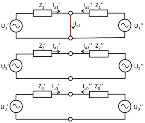
Figure 3.3.: Reduced Sequence Networks Interconnection for Three-Phase Fault. No Negative or Zero Sequence Network Component
• ZÕ
1,Z2Õ, Z0Õ - Positive, Negative and Zero Sequence Impedance of Generator at bus B’ and Line Part 1
• Z1ÕÕ,Z2ÕÕ,Z0ÕÕ- Positive, Negative and Zero Sequence Impedance of Generator at bus B” Line Part 2
From Equation A.1 in Appendix A it can be seen that the positive sequence current, Ia1, is equal to the fault current, IF. This is illustrated in Figure 3.3.
In other words, the original three-phase system can be represented with just the positive sequence components of the symmetrical components, which is the same as the original phasors (ref. Equation A.2).
IF =Ia1 =IaÕ1+IaÕÕ1 (3.1)
In this case, the relay at bus B’ will not see the entire fault current, it will see the current contribution flowing from bus B’:
IaÕ1 =IaÕ = U
Õ
1 ZÕ
16 CHAPTER 3. SHORT-CIRCUITS AND ABNORMAL CONDITIONS
3.2. Phase-to-Ground Faults
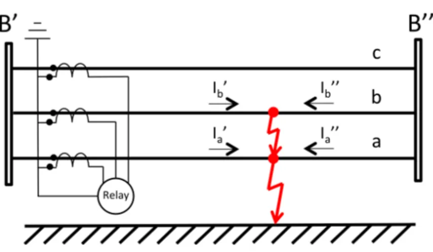
Figure 3.4.: Phase-to-Ground Fault
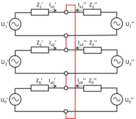
Figure 3.5.: Reduced Sequence Networks Interconnection for Phase-to-Ground Fault
Single Phase-to-Ground faults are the most common fault types in common three-phase networks. They may be caused by direct or indirect lightning strokes, leading to transient overvoltages. Falling trees or other objects may also lead
3.2. PHASE-TO-GROUND FAULTS 17
to a short circuit between phase and ground.[15] In a situation where Phase a experiences a bolted fault to ground, as illustrated in Figure 3.4, the current in Phase b and c becomes zero, while Phase a will carry the entire fault current:
Ia=IF
Ib = 0
Ic = 0
(3.3)
Inserting this into Equation A.1 leads to the following relationship:
Ia1 =Ia2 =Ia0 = Ia 3 = UÕ 1 ZÕ 1+Z2Õ +Z0Õ + UÕÕ 1 ZÕÕ 1 +Z2ÕÕ+Z0ÕÕ (3.4) The currents can be divided up in to the two parts as earlier:
Ia =IaÕ +IaÕÕ
Ia1 =IaÕ1+IaÕÕ1
Ia2 =IaÕ2+IaÕÕ2
Ia0 =IaÕ0+IaÕÕ0
(3.5)
The fault current may then be expressed as follows:
IF =Ia= 3Ia1 = 3Ia2 = 3Ia0 = 3UÕ 1 Z1Õ +Z2Õ +Z0Õ + 3UÕÕ 1 Z1ÕÕ+Z2ÕÕ+Z0ÕÕ (3.6)
This can be represented by connecting all of the sequence networks in series, as shown in Figure 3.5. Again, the relay will only see the current from bus B’:
IaÕ = 3U Õ 1 ZÕ 1+Z2Õ +Z0Õ (3.7) If ZÕ
1 = Z2Õ = Z3Õ, then the relay will see the a current of the same magnitude during a Three-Phase-to-Ground Fault as during a Phase-to-Ground Fault.
18 CHAPTER 3. SHORT-CIRCUITS AND ABNORMAL CONDITIONS
3.3. Phase-to-Phase Faults
Figure 3.6.: Phase-to-Phase Fault
Figure 3.7.: Reduced Sequence Networks Interconnection for Phase-to-Phase Fault. No Zero Sequence Network Component
When two phases in a three-phase system comes in contact with each other it is called a phase-to-phase fault. This is an asymmetrical fault. Consider a case where Phase a and b are the faulted phases. Then the currents in the phases
3.4. DOUBLE-PHASE-TO-GROUND FAULTS 19
would be of equal amplitude, with reverse polarity, and the current in Phase c will be zero:
Ia =IaÕ +IaÕÕ =IF
Ib =IbÕ +IbÕÕ=≠IF
Ic = 0
(3.8)
Assuming the respective positive and negative sequence impedances are equal, Equation A.1 yields the following expression for the magnitude of the fault cur-rent: IF =Ia = Ô 3UÕ 1 2ZÕ 1 + Ô 3UÕÕ 1 2ZÕÕ 1 (3.9)
This shows that the magnitude of the fault current during a bolted phase-to-phase fault is Ô3
2 ¥0.866 to the one of a bolted three-phase fault.
In the same way as before the relay will only see the current contribution from bus B’, which in this case is IÕ
a and IbÕ.
3.4. Double-Phase-to-Ground Faults
Figure 3.8.: Double-Phase-to-Ground Fault
Double-Phase-to-Ground faults occur when two phases come in contact with each other and ground at the same time. It occurs relatively rarely, nevertheless it should be mentioned.
20 CHAPTER 3. SHORT-CIRCUITS AND ABNORMAL CONDITIONS
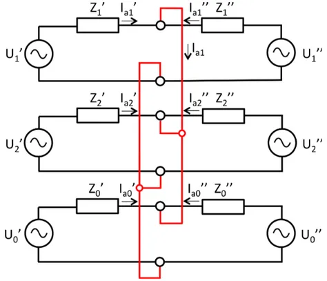
Figure 3.9.: Reduced Sequence Networks Interconnection for Double-Phase-to-Phase Fault
Figure 3.8 illustrates a Double-Phase-to-Ground Fault where Phase a and b are faulted. The current in Phase c becomes zero, Ic = 0. This fault can be
represented by interconnecting the three sequence networks in parallell. This gives: Ia1 =IaÕ1+IaÕÕ1 = UÕ 1 ZÕ 1+ Z Õ 2Z0Õ ZÕ 2+Z0Õ + U1ÕÕ ZÕÕ 1 + Z ÕÕ 2Z0ÕÕ ZÕÕ 2+ZÕÕ0 Ia2 =IaÕ2+IaÕÕ2 =≠Ia1 A ZÕ 0 ZÕ 2+Z0Õ + ZÕÕ 0 ZÕÕ 2 +Z0ÕÕ B Ia0 =IaÕ0+IaÕÕ0 =≠Ia1 A Z2Õ ZÕ 2+Z0Õ + Z2ÕÕ ZÕÕ 2 +Z0ÕÕ B (3.10)
The relay at bus B’ will also here just see the proportion of the fault currents coming from bus B:IÕ
4. Protection Principles
There exists several different protection techniques and principles. Fuses are the simplest and cheapest technology, however they need to be manually replaced when they melt (operate). Protective relays are used when fuses are not feasible. Different relays can have different inputs, and they will treat the information differently, but their objective is shared; to correctly detect and clear a fault as soon as possible. A closer look at overcurrent, distance and differential relay principles will be made in this chapter, as they are the most common protection applications in power systems today. Other protection principles also exists, e.g. overvoltage, undervoltage, volts per Hertz, however they are not the scope of this thesis.
4.1. Fuses
The first type of protection for electrical networks were fuses. As they are simple and cheap, they are still commonly used for protection purposes today. The most common type of fuses consists of a short conducting wire inside a casing, capa-ble of carrying the current permitted for the protected zone. The cross-section and material of the wire decides how much current the fuse can conduct without melting. The wire will melt if the temperature increase caused by the current going through the fuse, which has some resistance, becomes higher than the melt-ing temperature of the wire material. The fuse can melt almost instantaneously or with some time delay as seen in Figure 4.1. A melted fuse will need to be manually replaced, and this is one of the drawbacks of using fuses for protection. Overcurrent relays, which will be looked at later in this chapter, can have a time-current characteristic similar to fuses.[33]
Figure 4.1.: Time-Current Characteristics for a Fuse[19]
22 CHAPTER 4. PROTECTION PRINCIPLES
4.2. Overcurrent Relay
In most cases fault currents are several times higher than load currents. In other words, currents significantly higher than load currents equals fault. This simple principle is what overcurrent relays is based on. The inputs of overcurrent relays are currents from CTs, which continuously measure currents flowing in the system. Normally, in a three-phase system, there are three CTs per location, one per phase. This supplies the relay with information about current in each phase, as well as the current flowing in the neutral (ground). The current in the neutral is normally measured by joining the three phase leads inside the physical relay itself, as illustrated in Figure 4.2. In a perfectly symmetrical system the current in the neutral will be zero (Kirchoff’s law). During an asymmetrical fault this current will be of significantly higher magnitude. This principle is therefore used as a fault indicator in overcurrent relays.
Figure 4.2.: Connection of Current Transformers for Overcurrent Relay Overcurrent relays operate with inverse/definite time and instantaneous char-acteristics. The relays have a set pick-up current, Is, and when the current
reaches and/or surpasses this value a timer starts. The relationship between the magnitude of the current and the time needed for tripping is inverse or definite. When the timer reaches its corresponding point on the time-current curve, with-out the current dropping, the relay will trip. The relay will trip instantaneously if the current reaches the instantaneous trip setting. An example is shown in Figure 4.3. The inverse curves are usually divided into normal, very or extreme inverse characteristics. ANSI and IEC have standards for the characteristics of these time-current curves (TCCs) which are commonly used, however the user may choose/create tailored characteristics.[2]
4.2. OVERCURRENT RELAY 23
Figure 4.3.: Inverse Time and Instantaneous Characteristics - Overcurrent Protection
The setting of the pick-up current is the key element for overcurrent protection. This setting is crucial for the reliability of the protection system. Put differently, the relay should trip when it is supposed to, and should not trip when it is not supposed to. The relay should operate when there is a fault in its protection zone, or as remote back-up for downstream protection. It should not operate for high load currents or before downstream protection. To achieve this, relay coordination, is very important. Relays should be set so that they do not operate before downstream protection has time to operate, but still be able to operate, with a certain delay, if the downstream protection fails. The setting for overcur-rent relays may vary between situations, however a rule of thumb, is to set the pick-up current as follows:[14]
1.5IM axLoad < Is<0.8IM inF ault (4.1)
This provides a sufficient safety margin for fault and load current calculation errors.
The drawback of overcurrent relays is that they are not very good at pinpoint-ing the fault location. The impedance between two possible fault locations can be small, i.e. the fault currents are similar, compared to the impedance back to the CT location. This can make it hard for the relays to discriminate between a fault inside or outside its zone.
24 CHAPTER 4. PROTECTION PRINCIPLES
4.3. Directional Overcurrent Relay
A regular overcurrent relay is not sensitive to the direction of the measured current. An overcurrent relay only looks at the magnitude of the current and will initiate pick-up and trip according to its time-current characteristics, regardless of the way the current is flowing. In many power system scenarios it can be very beneficial to have an overcurrent relay that is sensitive to both magnitude and direction of the current flow, i.e. a directional overcurrent relay. This can increase the selectivity and the reliability (ref. Chapter 2.4) of an overcurrent relay application significantly.
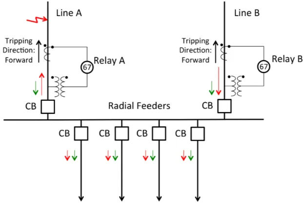
Figure 4.4.: Simplified One Line Diagram of Substation with Directional Over-current Relay
Figure 4.4 illustrates a substation with two main transmission lines, i.e. Line A and Line B, supplying four radial feeders with power. The main transmission lines are protected with a directional overcurrent relay, i.e. Relay A and Relay B (the busbar will have its own protection, which is not illustrated here). The green arrows illustrate how the current in the network will flow during normal operation.
4.3. DIRECTIONAL OVERCURRENT RELAY 25
If a fault were to occur at one of the transmission lines, e.g. at Line A as illustrated, current will flow from Line B, via the busbar, and upstream in Line A towards the fault, while still supplying load current to the feeders. The current flow during this fault is illustrated with the red arrows. In other words; Relay B will see a higher current than the relay in Line A during this scenario. If the relays have pick-up and time-current characteristics similar to each other and initially assume they have no directional element, it is possible that Relay B will trip before Relay A. However, ideally, Relay A is supposed to operate first as it is the primary protection for Line A. Assuming the relays now are directional, with forward tripping directions, i.e. towards protected object, Relay B will be blocked during the fault, due to the direction of the current it sees. This will lead to high selectivity as Relay B will trip first and clear the fault.
A reference, commonly referred to as polarizing quantity, is used to provide the directional function. This reference, either voltage or current, is utilized by the relay to compare the angle, „, between the measured current, ICT, and the
reference, to determine the direction of the current flow. Normally, a voltage quantity is used as a reference, as seen in Figure 4.4 and shown in the phasor diagram in Figure 4.5 as Uref, since a current reference may not be non-zero at
all times.
Figure 4.5.: Phasor Diagram for Directional Relay using Voltage Reference. Based on Figure 194 in [2]
The tripping direction of the directional overcurrent relay can be set to forward, reverse or it can be both, i.e. having a regular overcurrent function. Forward direction is usually defined towards the protected object, which normally also is towards the grounded side of the CT, as in the example in Figure 4.4. Reverse direction is naturally the opposite.
26 CHAPTER 4. PROTECTION PRINCIPLES
4.4. Distance Relay
Distance relays, sometimes referred to as impedance relay, measure the impedance of its protected unit, e.g. a line, using current and voltages supplied by CTs and VTs. The relay have been provided with the calculated impedance of the line, and continuously compare the two. Should the measured impedance at any time drop below the known line impedance, it will know that there is a fault and trip.
Figure 4.6.: Distance Relay Principle
Since the relay relies on measured values from transducers, and compares it with a calculated value, some safety margin is necessary. It is common to let the relay under-reach the line by 15-20 %, to make sure it does not operate before other relays downstream when it is not supposed to. This is illustrated in Figure 4.6 (Zone 1). To provide remote back-up for the relays protecting adjacent lines, the relay has another setting which over-reaches into the adjacent line (Zone 2). Typically the setting is 125-130%of the impedance of Line 1. This setting has an added intentional time delay, to make sure the primary protection has a chance to operate first. A third protection zone is also common, and it will function as remote back-up for an even greater portion of adjacent lines. An extra, longer time delay is added here.[21] The distance relays will have protection zones in both directions, however this is not illustrated in Figure 4.6.
Traditionally relay settings have been in secondary values. However, with the introduction of modern transducers, e.g. optical CTs, which have no ratio, and therefore no secondary value, it is common that modern relay have settings in primary values.[2]
4.4. DISTANCE RELAY 27
On the other hand, if a distance relay were to use secondary values, the impedance settings must be converted:
Zsec =Zpri·
CT R
V T R (4.2)
Where CTR and VTR are the ratios of the current and voltage transformer.
Figure 4.7.: Line 1 from Figure 4.6 with Mid-Line Fault
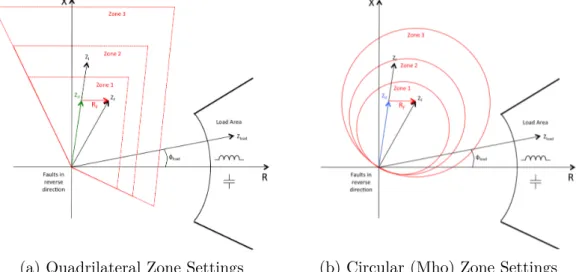
(a) Quadrilateral Zone Settings (b) Circular (Mho) Zone Settings Figure 4.8.: Corresponding RX-diagrams with Zone Settings, Line, Load and
Fault Impedances for Line 1 in Figure 4.7
The impedance settings for the different zones are normally shown using an impedance, or RX-diagram. Modern numerical distance relays have the ability to let the impedance characteristics have whichever shape is desirable, however they normally have a quadrilateral or circular shape.[35] Figure 4.8a displays an exam-ple of the settings of a distance relay with three zones. During normal operation, the distance relay will see the impedance of the line, Zl, plus the impedance of
the load, Zload. Under a fault the relay will see the impedance of the line to the
fault location,ZlF, and the impedance of the fault itself, here illustrated with an
28 CHAPTER 4. PROTECTION PRINCIPLES
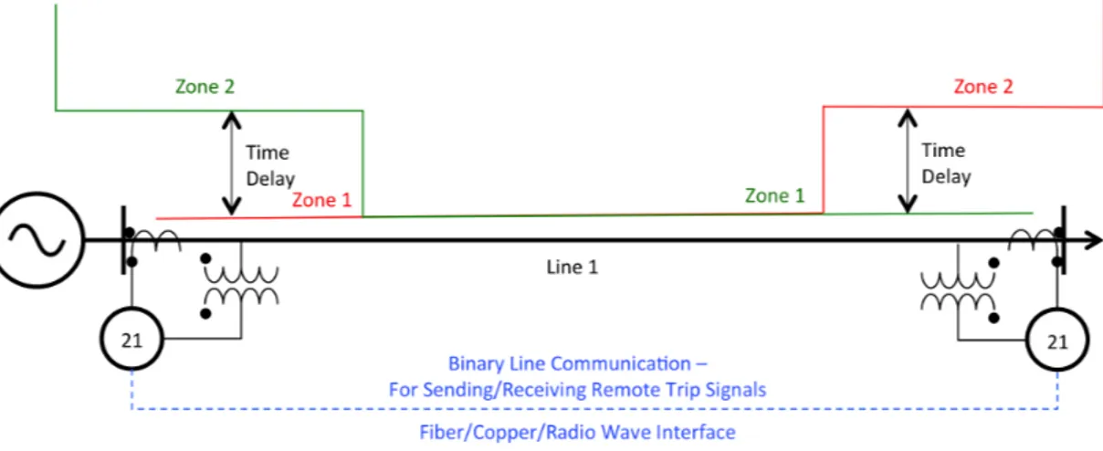
A common application for distance protection of a line is to have two distance relays at both ends of the line looking towards each other, as seen in Figure 4.9. The zone settings of the relays are set equal and in opposite direction, with Zone 1 normally being set to 80-85 % of the line length. The main purpose of using dual relays is to improve reliability for far-bus faults, i.e. faults outside of Zone 1. Assuming a fault occurs close to bus B, Relay A will see the fault in Zone 2, while Relay B will see it in its Zone 1. This means Relay A will have longer operating time than Relay B, due to the added time delay. To improve operating time, and allow both relays to operate instantaneously communication between the relays can be added. The communication can be simple with transferring of one or more boolean variables, i.e. trip signals and breaker positions. This type of communication can be made over radio wave, copper wire or fiber optic cables. For more advanced communication, with transmission of, for instance, time-stamped current and voltage values, fiber optic communication according to the IEC61850 standard (ref. Chapter 5.4/5.5) is used.
4.5. DIFFERENTIAL RELAY 29
4.5. Di
ff
erential Relay
Differential relay protection is considered to be one of the most versatile protection techniques available today.[15] A differential relay compare two or more currents flowing into and out of the protected zone/equipment. The basic principle relies on the fact that under normal conditions, the current(s) entering the zone should be equal to the current(s) leaving it. If this condition is not satisfied, it is an in-dication that there is a fault within the zone. This makes differential relays ideal for the protection of generators, transformers, busbars and transmission lines.[15]
Figure 4.10.: Differential Relay Principle
Figure 4.10 illustrates the basic principle of differential relay protection. This relay has an input of two currents, however it is possible for a differential relay to have additional inputs, if protection of the zone/equipment requires it. The protection of a busbar with a differential relay is an example which may require more than two current inputs.
Ip is the current that flows through the zone during normal operation. The
relay’s input is the secondary current from both sides, i.e. the primary current times CT ratio, minus the respective excitation current. The CT ratios will be equal, unless there is a transformer within the protected zone. If that is the case, the CT ratios will be set so that secondary currents will be equal. Kirchoff’s law yields that the relay will have zero contribution from the secondary currents. The excitation currents however, Ie1, Ie2, can not be considered to be equal at
all times. They are dependent on the burdens R1 and R2, which is proportional to the length of the cables between CTs and the relay. If the respective length of the cables are significantly different, the excitation currents may differ. In
30 CHAPTER 4. PROTECTION PRINCIPLES
addition, the excitation currents is inversely proportional to the CT ratios, as shown in Chapter 2.2. If they are different the excitation currents characteristics may also be different. The operating current, IOP, which the relay sees will then
be the difference between the two. An important design criteria for differential protection systems is therefore to take this into account when placing, sizing and setting the components.[21]
During an internal fault, both fault currents will flow into the zone. The magnitude of the currents will also, in most cases, be much higher than normal operation currents. The fault currents will not necessarily be equal, as they are dependent on the external system on both sides. This will lead to an increased operating current,IOP F.
Percentage differential relays are the most common type of differential relays[15]. They compare a restrain current with the operating current; if the operating cur-rent IOP is greater than the restrain current IRES times a gradient m, it will
operate. A lower gradient will increase the sensitivity of the relay. Figure 4.11 shows the current characteristics of a typical fixed percentage differential relay. It has two gradients m1 and m2. m2 is greater to improve security at high restrain currents. To add security at low restrain currents, the operating current has a minimum pick-up value.
4.5. DIFFERENTIAL RELAY 31
One of the main problems with differential protection is that the CTs may ex-perience different degrees of saturation. External faults may lead to high through currents of the protected object and may cause the corresponding CTs to satu-rate, creating distorted waveforms, leading to an unnecessary tripping. Carefully selecting CTs for each protection scenario is therefore important. Figure 4.12 displays how the secondary current affected by CT saturation compared to the actual secondary current.
Figure 4.12.: Secondary Current Waveforms with/without CT Saturation
Another limitation for differential relays are that they can not protect a zone where the distances from CTs to the relay is long or varies too much. This is because the error of the CTs are dependent on the burden, which again is pro-portional to the length of the cables connecting the CTs and the relay. For the protection of a long line, it is therefore common to have two differential relays with corresponding CTs on each side of the line, and communication able to trans-fer current values between the two relays. For the protection of transmission and distribution lines, the relay engineer must be aware of the challenges occurring when energizing a line. Due to the shunt capacitance (length dependent) of a line, a significant capacitive current will flow in the line during energizing/de-energizing. This current contribution may not be equal at both sides, so the relay should block during this phenomena.
The described principles and challenges are valid for differential protection of busbars, transformers and generators, however some extra considerations must be made for these components.
32 CHAPTER 4. PROTECTION PRINCIPLES
4.5.1. Generator Di
ff
erential Protection
A generator is normally protected with several types of protective relay functions in addition to differential protection, e.g. volts per Hertz (overexcitation), ther-mal overload and overvoltage protection. The number and types of protection will vary with the size, type, location and significance of the generator. However, differential protection is almost always a part of the protection system for gener-ators, as it provides fast and sensitive protection for internal generator faults. It is not always used on generators under 1 MVA.[15]
Differential protection needs two sets of current transformers; one at the gen-erator terminals and one in the neutral leads. It is common that they have the same ratio, and preferably be of the same model, to reduce potential mismatch errors for external faults. Since a generator can be wye- or delta-connected it is important that this is taken into consideration when setting the relay. The percentage characteristics, or gradients, m1/(m2), are usually set to a relatively low value, typically to 10-25 %, to increase sensitivity.
4.5.2. Transformer Di
ff
erential Protection
For the protection of transformers over 10 MVA, differential protection is widely used. This is due to the same reasons as to why they are used for generators; it provides fast, reliable and sensitive protection. Transformers normally have two windings, with a primary and secondary side, requiring one set of CTs on each side. In some cases one may encounter a three-winding transformer, which naturally would require three sets of CTs, i.e. on the primary, secondary and ter-tiary. Transformer differential protection is normally configured with a variable percentage characteristics. In other words this means the slope of the gradient increases with increasing restraint current. The change is either continuous or in discrete steps. This characteristics is used to prevent mis-operation due to CT saturation during external faults.
When designing a differential protection scheme for a transformer, one faces some extra challenges which needs to be taken into account:
• Magnetizing Inrush Current
• Overexcitation
• Different Voltage LevelsæDifferent CT Types, Ratios and Characteristics
• Wye/Delta/Zigzag Winding Combinationsæ Phase Shifts
4.5. DIFFERENTIAL RELAY 33
Magnetizing Inrush Current
During a rapid change in the voltage applied to a transformer, a current tran-sient, known as magnetizing inrush current may occur. This is caused by an exciting current trying to create flux in the transformer corresponding to the change applied voltage. Magnetizing inrush current can, in other words, occur during energizing of the transformer itself, during energizing of a nearby trans-former or during other faults in the network which causes a momentary voltage dip. Initially, the magnetizing current may be up to 8-30 times higher than full-load current. The current decays to normal exciting current after some time, typically the time constant can be everything from 10 cycles to 1 minute, de-pending on several factors, most notably the resistance and stray losses in the transformer. This phenomena is important to be aware about when applying differential protection to a transformer, is at can cause unbalance to the currents measured by the CTs, and falsely indicating an internal fault and leading to un-necessary tripping. The differential relay should therefore be able to detect the phenomena when it happens and block the relay for the required period.[15] Overexcitation
Overexcitation is caused by overvoltage and/or underfrequency, and it may lead to saturation of the transformer and subsequent heat buildup and internal dam-age. Larger transformers usually have separate protection for overexcitation, as differential protection is not practical to use explicitly for this. However, overexcitation is a concern for differential protection as it can lead to tripping on overexcitation far below dangerous values. The relay should in this case be blocked from operating currents caused by overexcitation.[15]
Different CT Characteristics due to Different Voltage Levels
A transformer will have different voltage levels at the different terminals. To compensate for this, the ratio of the CTs at each terminal is chosen accordingly, so that secondary currents, i.e. the current that the relay sees, has the same base value on all terminals. Due to the needed difference in CT ratio one may come across sets of CTs of a different type/model and/or from a different manufacturer. This can also mean that the CTs will have different performance characteristics. This is another factor that must be taken into account.[15]
34 CHAPTER 4. PROTECTION PRINCIPLES
Phase Shifts
Depending on how the transformer windings are connected to each other on each side, there may be a phase shift from one side to the other. For instance will a delta-wye connected transformer, experience a phase shift where the delta side will lead the wye side with 30¶. It is therefore important to input correct
information about each respective winding, when setting the relay.[15][28] Tap-Changing Transformers
Selected transformers can have the possibility of adjusting the ratio with built-in tap-changers. This feature is used for voltage control to achieve desired power system operation, e.g. controlling reactive power flow, and is in most cases con-trolled remotely. Normally, the tap-changers are able to adjust the voltage ratio by±10%. Since CTs are set at a fixed ratio, this is a concern for the purpose of differential protection. Some CTs, as previously mentioned, may have multiple tap settings, but their intention is not to be remotely controlled, e.g. to accommo-date tap-changing transformers. By setting the CT ratio according to the center of the voltage range, the error is minimized to half of the overall voltage range. For a transformer with a tap-changing voltage range of ±10 %, the maximum error caused by the tap-changer is 10%. Selecting the percentage characteristics for the differential protection accordingly, to prevent mis-operation, is therefore vital when dealing with tap-changing transformers.[15]
4.5.3. Busbar Di
ff
erential Protection
The main challenge when applying differential protection of busbars is achiev-ing sufficient selectivity to avoid mis-operation during close-in faults, i.e. faults in close proximity of the bus, but outside the bus protection zone. CT satura-tion may occur during close-in faults and the busbar differential protection must therefore be accordingly delayed to coordinate with the relay providing the pri-mary protection function for the adjacent, faulted line. In some cases distributed devices for each line connected to the bus which transmits measured values to a central unit. The differential function is then performed in the central unit, which compares the values from all lines continuously. There exist other types of busbar differential protection which are commonly used, e.g low-impedance and high-impedance differential protection, however they will not be described closer in this report.[28]
5. Modern Relay Technology
The technology behind microprocessors continuously improves, leading to them becoming more powerful, faster and smaller. Todays modern relays, commonly referred to as Intelligent Electronic Devices (IEDs), are microprocessor based devices. This technology development has allowed relay manufacturers to make complex devices containing several protective functions, as well as metering, event recording functions and communication features.
This all-in-one philosophy lets one device replace the functions of several stand alone devices, significantly decreasing investment costs. Should one protective function not operate as intended during a fault, another function will detect and cause the relay to trip. For instance; if there is problems with a VT, leading to the distance protection not being dependable (the relay should detect this and disable the distance function), the overcurrent protection function will detect the fault and operate. This is in Chapter 2.4 referred to as local back-up.
However, should the entire relay fail, one is left without protection, unless there is a separate relay (similar or different model) providing redundancy. Digi-tal relays have two main sources of error; hardware and software, software being introduced by the transition into digital relays. Periodic, maintenance testing of relays, to ensure their reliability, especially after software updates/revisions, is therefore key. To avoid potential recurring problems, it might be beneficial to install relays of a different model/series, or perhaps even better; from a different manufacturer. A redundant protection system is also important to have since re-lays has to been to taken out of service for maintenance testing. The alternative; testing relays while leaving the system unprotected, is not viable.
The increased complexity of modern digital relays provides challenges for relay operators. Software allows the number of settings for the different integrated protective functions to be substantial. It is therefore important that the relay operator is well known with the capabilities of the relay and its software, to pre-vent misapplications. The software of the relays are also frequently updated and it requires the operator to stay up-to-date, as software updates may bring new and added functions, but also change existing functions.[32]
36 CHAPTER 5. MODERN RELAY TECHNOLOGY
Figure 5.1.
![Figure 2.3.: Equivalent Circuit for a Current/Voltage Transformer. Based on Figure 2.3 in [33] and Figure 5.6 in [15]](https://thumb-ap.123doks.com/thumbv2/123dok/1264850.2501848/23.892.137.761.163.350/figure-equivalent-circuit-current-voltage-transformer-figure-figure.webp)
![Figure 2.6.: Cross-Section of a Coupling Capacitive Voltage Transformer from Alstom Grid[11]](https://thumb-ap.123doks.com/thumbv2/123dok/1264850.2501848/26.892.178.710.533.1016/figure-cross-section-coupling-capacitive-voltage-transformer-alstom.webp)