Experimental Thermal and Fluid Science
AIMS AND SCOPEExperimental Thermal and Fluid Scienceprovides a forum for original, previously unpublished research emphasizing experimental work that enhances understanding of heat transfer, thermodynamics, and fluid mechanics and their applications. Also covered in the abstract and citation database ScopusÒ. Full text available on ScienceDirectÒ
ETFS also covers research results in combined heat and mass transfer, multiphase flow, combustion, radiative transfer, porous media, cryogenics, turbulence, contact resistance, microscale and nanoscale thermal fluid systems and thermophysical property measurements and techniques. Papers related to the development of new experimental methods, visualization techniques, and instrumentation are an important part of this Journal.
Experience gained and lessons learned in building test facilities and in measuring and reducing test data are important aspects of any experimental work. Some of these papers include micro-electromechanical systems; medical and biological systems; and thermal and flow control in both the internal and external environment. Authors are encouraged to report this experience and to summarize the original data.
Journal Homepage Description forExperimental Thermal and Fluid Science
Experimental Thermal and Fluid Scienceprovides a forum for research emphasizing experimental work that enhances basic understanding of heat transfer, thermodynamics and fluid mechanics, and their applications. In addition to the principal areas of research, the journal covers research results in related fields, including combined heat and mass transfer, micro and nanoscale systems, multiphase flow, combustion, radiative transfer, porous media, cryogenics, turbulence, contact resistance, and thermophysical property measurements and techniques. Archival review papers, short communications, invited papers, letters to the Editor, discussions of previously published papers, and book reviews are regular features of the journal, in addition to full-length articles.
Editors-in-Chief
N. Selc¸uk
Department of Chemical Engineering,
Middle East Technical University,
06531 Ankara, Turkey
Tel.: +90-312-2102603
Fax: +90-312-2102600
E-mail: [email protected]
G.P. Celata
ENEA,
Institute of Thermal-Fluid Dynamics,
Via Anguillarese 301,
00123 Santa Maria di Galeria, Rome, Italy
Tel.: +39-06-3048-3905
Fax: +39-06-3048-3026
E-mail: [email protected]
Editors
C. Colin
Institut de Me´canique des Fluides de Toulouse UMR 5502 CNRS-INP-UPS 2, Alle´e Camille Soula, 31 400 Toulouse France
Tel.: 33 (0)5 34 32 28 25 Fax: 33 (0)5 34 32 29 91 E-mail: [email protected] M.H. Kim
Department of Mechanical Engineering Pohang University of Science and Technology
San 31, Hyoja-Dong, Nam-Gu, Pohang, Kyeongbuk, 790-784, South Korea
E-mail: [email protected] T.M. Liou
National Tsing Hua University Taiwan, ROC
Tel.: +886-3-5742607 Fax: +886-3-5729716
E-mail: [email protected]
B.J. McKeon Professor of Aeronautics Graduate Aerospace Laboratories California Institute of Technology 1200 E. California Blvd, MC 301-46 Pasadena, CA 91125, USA E-mail: [email protected] D.V. Pence
Professor of Mechanical Engineering Oregon State University, 204 Rogers Hall Corvallis, OR 97331-6001, USA Tel.: 541-737-7018
Fax: 541-737-2600
E-mail: [email protected] G. Ribatski
Department of Mechanical Engineering S~ao Carlos School of Engineering (EESC) University of S~ao Paulo
Av. Trabalhador S~ao-carlense, 400, Pq Arnold Schimidt 13566-590 S~ao Carlos - SP, Brazil Tel.: +55 16 3373 9415 Fax: +55 16 3373 9402 E-mail: [email protected]
S.K. Saha
Mechanical Engineering Department Bengal Engineering and Science University Shibpur
Howrah 711 103, West Bengal, India Tel.: +919830493430 Fax: +913326682916
E-mail: [email protected] I. Satoh
Japan Tokyo Institute of Technology Tokyo, Japan
Tel.: +81-3-5734-3238 Fax: +81-3-5734-2945 (Office)/
+81-3-5734-3917 (Department) E-mail: [email protected] C.W.M. van der Geld
Technische Universiteit Eindhoven Eindhoven, Netherlands Tel.: +31-40-247-2923 Fax: +31-40-247-5399
E-mail: [email protected]
S. Wongwises
Department of Mechanical Engineering King Mongkut’s University of Technology Thonburi
126 Bangmod, Tongkru, Bangkok 10140, Thailand
Tel.: +662-4709115 Fax: +662-4709111
E-mail: [email protected]
Publication information:Experimental Thermal and Fluid Science(ISSN 0894-1777). For 2015,Volumes 60 to 69are scheduled for publication. Subscription prices are available upon request from the Publisher or from the Elsevier Customer Service Department nearest you or from this journal’s website (http://www.elsevier. com/locate/etfs). Further information is available on this journal and other Elsevier products through Elsevier’s website (http://www.elsevier.com). Subscriptions are accepted on a prepaid basis only and are entered on a calendar year basis. Issues are sent by standard mail (surface within Europe, air delivery outside Europe). Priority rates are available upon request. Claims for missing issues should be made within six months of the date of dispatch.
Founding Editors:
R.K. Shah, E.N. Ganic´Editorial Advisory Board
S. Aleekseenko,Russia
N. Brauner,Israel
J.M. Corberan,Spain
P. Di Marco,Italy
I. Golobic,Slovenia
S. Kakac,Turkey
T. Karayiannis,UK
M. Kawaji,Canada
I. Kennedy,USA
K.T. Kiger,USA
J-H. Kim,USA
S.Y. Ko,China
N.W.M. Ko,Hong Kong
I. Marusic,Australia
G. Nathan,Australia
R.E. Nigmatulin,Russia
T. Okawa,Japan
M. Ozawa,Japan
B. Palm,Sweden
D. Pence,USA
L. Smits,USA
J. Soria,Australia
P. Stephan,Germany
S.P. Sukhatme,India
A. van Steenhoven,The Netherlands
Visualization of the boiling phenomenon inside a heat pipe using
neutron radiography
Nandy Putra
a,⇑, Ranggi Sahmura Ramadhan
a, Wayan Nata Septiadi
a,b, Sutiarso
ca
Heat Pipe Technology Research Cluster, Heat Transfer Laboratory, Department of Mechanical Engineering, University of Indonesia, Kampus UI-Depok, 16424, Indonesia
b
Departement of Mechanical Engineering, University of Udayana, Kampus Bukit Jimbaran, Bali, Indonesia
c
Centre of Science and Technology of Advanced Materials, National Nuclear Energy Agency of Indonesia (BATAN), Indonesia
a r t i c l e
i n f o
Article history:Received 13 August 2014
Received in revised form 28 February 2015 Accepted 28 February 2015
Available online 17 March 2015 Keywords:
Heat pipe Visualization Neutron radiography
a b s t r a c t
Heat pipes are effective heat exchangers that have a wide range of applications because of their ability to passively transfer large amounts of heat. Research into heat pipe technology has dramatically increased over the last decade and, more recently, has incorporated the use of visualization to help researchers gain a better understanding of the boiling phenomenon and heat transfer occurring inside a heat pipe. Neutron radiography is one method of visualization suitable for use in heat pipe investigations due to unique attenuation characteristics of neutrons attaching to various materials. In this study, an alu-minum-based heat pipe was tested using working fluid filling ratios from a 10% to 90% capacity. Visualization using neutron radiography was conducted at a neutron radiography facility, RN1, under the supervision of the Centre of Science and Technology of Advanced Materials (PSTBM), National Nuclear Energy Agency of Indonesia (BATAN). Using temperature and pressure sensors, this study revealed that the optimum value of working fluid filling ratios directly correlates to the pressure inside a heat pipe and the size of vapor space available. The neutron radiography facility maintains high neutron flux at 106–107n/cm2s; high quality images were captured utilizing this radiography visualization tech-nology. The captured images demonstrate that the boiling phenomenon inside a pressure-reduced heat pipe varies when compared with the boiling phenomenon at atmospheric pressure. The visualization result also shows the importance of wick structure in pumping return condensate from the condenser to the evaporator.
Ó2015 Elsevier Inc. All rights reserved.
1. Introduction
Heat pipes are passive heat exchangers operating on the two-phase principle. The passive description refers to lack of additional energy needed during operation; two-phase indicates that the heat pipe uses the phase change phenomenon of working fluids as the main mode of heat transfer[1,2]. A heat pipe may have circular or rectangular cross sections and generally contains a vacuum con-tainer with a wick structure and a working fluid. When heat is applied to the evaporator, the working fluid evaporates and rushes to fill the evacuated space. As the vapor enters, it contacts the wall of the lower temperature heat pipe. The vapor then condenses and releases latent heat. This condensate naturally flows back to the evaporator, either by gravity or capillarity action induced by the wick structure. The high amount of latent heat needed during
the phase change process enables the heat pipe to have higher effective thermal conductivity[3,4].
Heat pipes used for various cooling systems have been exten-sively tested for many applications such as central processing units (CPUs) hard disks, light emitting diodes (LEDs) lamps, avionics and various medical devices including those used in cryosurgery and vaccine transport mechanisms[5–11]. Heat pipe components for each application were investigated for optimum performance. Wick structures were made of biomaterials, bi-porous structures, sintered powder, grooved assemblies and metal foam [12–16]. Working fluids such as nanofluids, methanol, acetone, propylene glycol and refrigerant have also being tested[17–20].
Another parameter affecting heat pipe performance is the work-ing fluid fillwork-ing ratio. This ratio is the volumetric measure of fluid injected into the heat pipe compared with the volume of evacuated space. Naphon et al.[21]tested vapor chambers on CPU cooling systems with various filling ratios and found that the optimum ratio of fluid to volume is 20%. Any ratio lower than 20% leads to the dry-out phenomenon; higher ratios, however, cause the liquid
http://dx.doi.org/10.1016/j.expthermflusci.2015.02.026
0894-1777/Ó2015 Elsevier Inc. All rights reserved.
⇑ Corresponding author. Tel.: +62 812 8781 557. E-mail address:[email protected](N. Putra).
Contents lists available atScienceDirect
Experimental Thermal and Fluid Science
layer to hamper heat transfer at the heat input region. Sukchana and Jaiboonma[22]investigated the effect of the filling ratio com-pared with thermal efficiency of a 10 cm, R-134a charged heat pipe. The investigation also showed the optimum value of filling ratio relates to the saturation pressure increment and temperature inside the heat pipe. Lips et al.[23]studied the effect of the filling ratio of a flat heat pipe and found that this ratio affects the thermal resistance of a heat pipe. Small filling ratios lead to dry-out at the evaporator while large filling ratios lead to flooding at the con-denser. Hussein et al.[24]investigated wickless heat pipes utiliz-ing various fillutiliz-ing ratios and found that a higher fillutiliz-ing ratio provided higher thermal capacity resulting in lower temperature and lower pressure at the same heat flux. Ong and Alahi[25]tested a R-134a filled heat pipe employing filling ratios in the range of 35–80% while discovering that the optimum-filling ratio was 80%. Lin et al.[26]studied heat pipes with silver-nanofluids at fill-ing ratios of 20%, 40%, 60% and 80%. The study revealed the opti-mum-filling ratio for successful heat transfer was 60%. Finally, Naphon et al. [27,28]tested heat pipes with both Titanium and R11 nanofluids across various filling ratios. This study established the optimum value of this ratio was 66% and 50%, respectively.
The heat transfer process ensuing inside a heat pipe with boil-ing workboil-ing fluids reduced the pressure and fluid circulation through the capillary structure. This complex process triggered the evaporation-boiling phenomenon inside the heat pipe to appear differently than more commonly assumed processes. The
visualization technique clearly proved these differences and pro-vided important outcomes toward the characterization of heat pipe operation. The visualization results also show the importance of wick structure to heat pipe operation[29–31].
Most visualization techniques used during heat pipe operations employ transparent media such as glass windows [32–35]. Radiography is one method of visualization that uses transmission imaging and is a technique that utilizes the penetration of radiative energy to non-destructively study the internal portions of opaque objects. Finally, neutron radiography uses neutron beam tech-niques to penetrate heavy materials while beam are absorbed by lighter materials. This technique is suitable for use in visualization of the two-phase flow of hydrogen-based fluids inside metal enclo-sures[36,37].
Mishima et al.[38] visualized and measured two-phase flow using neutron radiography, providing a result that could be used not only as a qualitative measurement but also as a quantitative measure. The need of high-speed video (HSV) technology with cap-ture speeds up to 1000 frame per second was also highlighted in this study. With an HSV camera, Mishima et al. were able to observe the characteristics of the two-phase flow and the vapor fraction. Uchimura et al. [39] stated that the inability of the glass-transparent pipe to hold high pressure, and temperature became the main disadvantage of the glass-based visualization method. They further used real time neutron radiography (RTNR) to visualize the two-phase flow of liquid metal and to calculate
the velocity of a bubble by tracing the centroid of the bubble from one image to another. Takenaka et al.[40] used neutron radio-graphy to visualize the flow of boiling during the two-phase cryo-genic cycle. Using the significant difference in attenuation coefficient between the fluid nitrogen and the heat exchanger base material aluminum, the boiling cryogenic fluid flow may be characterized. Asano et al.[41]visualized and measured the frac-tion of liquid–gas inside a plate heat exchanger with a CCD camera capturing images at 30 fps. The distribution of liquid–gas fraction became the basis of heat exchanger optimizing.
Borgmeyer et al. [42] used neutron radiography to study the heat transfer capability and fluid flow of oscillating heat pipe. They found that neutron radiography could help expose the physi-cal phenomenon and characteristics of the two-phase flow of working fluid inside an oscillating heat pipe. Meanwhile, Sugimoto et al. [36] evaluated the behavior of a working fluid inside a variable conductance heat pipe (VCHP), also with neutron radiography. Video operating at 30 fps captured visualization images while using an Electron Bombardment Charged Coupled
Device (EB-CCD). The radiography revealed significant changes to the results by the effect of adding a thin plate, changing the filling ratio or by varying the inclination angle.
Further investigation into the relationship between the working fluid filling ratio and the pressure inside a heat pipe are clearly needed. Visualization techniques using neutron radiography also needs further examination. This study measures the pressure and temperature inside an operating heat pipe with various filling ratios. Neutron radiography is utilized to visualize the activity inside the heat pipe during experimentation and was conducted at a neutron radiography facility, RN1 at The Centre of Science and Technology of Advanced Materials (PSTBM), National Nuclear Energy Agency (BATAN), Serpong, Indonesia.
2. Methods
The heat pipe sample was made of 2 mm thick aluminum with an outer diameter of 32 mm. A heat sink was attached at the
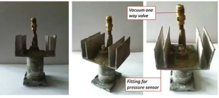
Fig. 2.Conceptual heat pipe design.
condenser; the heating surface at the evaporator was 5040 mm2. Aluminum was chosen as the heat pipe material due to its lower neutron attenuation coefficient compared with that of water. The difference of attenuation coefficient resulted in good contrast between aluminum as the metal enclosure of heat pipe and water as the working fluid, enabling the researchers to analyze the fluid within the enclosure more effectively.
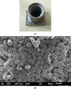
A structure of sintered aluminum powder was attached to the inner wall of the heat pipe, acting as a wick. The Wick structure is made of aluminum powder with maximum diameter of 100
l
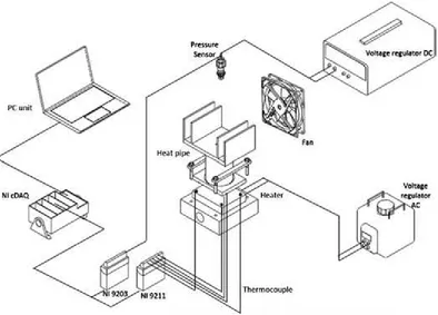
m. Picture of the wick structure and SEM image of the wick are shown inFig. 1. A second heat pipe was left wickless and is fur-thermore referred to as the thermosyphon. Both the original heat pipe and the thermosyphon were charged with water, the working fluid of choice, at various filling ratios ranging from 10% to 90%. Each heat pipe maintained a vacuum of 5 kPa. The value is the low-est that can be achieved by the vacuum pump and steadily main-tained by the heat pipe. The design sample and fabricated sample is inFigs. 2 and 3.An electric heater rated at 250 W was attached to the evap-orator to apply varying experimental heating loads of 9 W, 40 W and 96 W. The heat load is chosen in such range that it represents a low, medium and high load. The range is also represents the amount of load that produced by heat source in the real application such as computer’s CPU. To eject heat, an electric fan was attached to the heat sink. At the interface of the heater and evaporator, five type-K thermocouples were attached. A high precision and high resolution Autonics Digital PressureSensor PSA-C01was attached at the condenser to maintain reading with an accuracy of 1% F.S. and adequate pressure range of 101.3 kPa to 101.3 kPa, Both the temperature and pressure sensors then connected to two high precision data acquisition units, National Instrument (NI) 9203 and NI 9211. The experimental setup is shown inFig. 4.
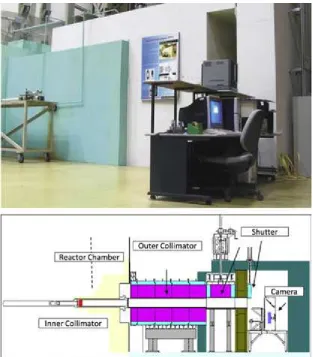
Neutron radiography was conducted at the neutron radio-graphy facility, RN1, and it used the scintillator detection method.
The neutron flux from the neutron beam tube was 106–107 n/cm2s. The collimator attached to the beam tube had the ratio of collimator total length and aperture diameter, L/D, of 83 with 60.95% thermal neutron, 0.78% scattered neutron, 0.48% gamma and couple production of 2.85% [42]. The neutron radiography facility can be seen in Fig. 5 shows the configuration of the scintillator method used in RN1. The neutrons from the beam tube were transmitted through the sample to the scintillator screen made of Li6-ZnS. The scintillator is a homogeneous plastic sheet containing a conversion material, lithium-6 fluoride (6LiF), and phospor, copper–aluminum and gold activated zinc sulfide (ZnS: Cu, Al, Au). The lithium absorbs neutron to form energetic helium and tritium atoms.
6Liþn¼3Hþ
a
þ4:78 MeV: ð1Þ
which cause ionization in the phosphor. Upon ionic relaxation, phosphorescent photons with a wavelength of 455 nm (blue light) are emitted, stimulating electronic excitations. As the electrons return to their ground-states, they emit photons with a wavelength of 565 nm (green light), which are detected by the CCD camera[43]
A mirror made of TiO2with 95% reflectivity was used to protect the camera from direct neutron beam, angled at 45°in relation to
the incoming beam. The scintillator screen, mirror and camera were kept in a dark enclosure to ensure only the light emitted by the scintillator was captured. The CCD camera was connected to a computer to read, display and record the data. The CCD camera used wasAndor Technology iKon – M DD934N BVwith resolution of 10241024 and microphone size of 1313. The camera main-tains 95%Quantum Efficiency(QE) for the wavelength, 350–800 nm, a 16 bit (65535) digitation. The experimental neutron radiography setup is shown inFig. 6. Images captured by this setup were pro-cessed using the processing software, ImageJ 1.47v. The images were then used to measure the height the working fluid pool and the gray level.
3. Results and discussion
3.1. Effect of working fluid filling ratio to evaporator temperature and thermosyphon pressure
This part of study was conducted using only the thermosyphon, which was made without aluminum wick structure attached to the inner wall. The thermosyphon was vacuumed to 5 kPa and charged with water to incrementally vary filling ratios by 10% from 10% to 90%. Each of the thermosyphons were loaded with uniform heating loads of 9 W, 40 W and 96 W. The evaporator temperature and pressure were recorded.
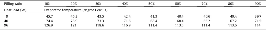
Fig. 7illustrates the evaporator temperatures at variable filling ratios with different heating loads.Table 1shows the steady evap-orator temperature of the thermosyphon at variable filling ratios and heating loads. There is an optimum value of working fluid fill-ing ratio that yields the lowest temperature at all of the heatfill-ing load variations, as extrapolated from the data found in both
Fig. 7andTable 1. For all 9, 40 and 96 W heating loads, the 10% fill-ing ratio exhibited the highest evaporator temperatures: 45.7°C,
74.4°C and 126.9°C. The incremental filling ratios then systemati-cally decreased the evaporator temperature, where the lowest evaporator temperature occurred at the 50% and 70% filling ratios. In this range, the evaporator temperature showed relatively iden-tical values for all heating load variations at 40°C, 68°C and
111°C for heating load wattage range. When the ratio increased
further to 80% and 90%, the evaporator temperature further
increased with results at the 90% filling ratio yielding 39.7°C,
71.5°C and 114°C for heating load.
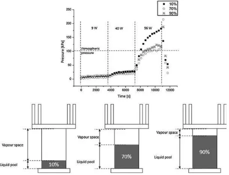
Fig. 8displays the effect of working fluid filling ratio to the pres-sure inside the thermosyphon. The relation between filling ratio and pressure has a similar trend to the relation between filling ratio and temperature. It is clear that the 10% filling ratio produces the highest pressure. In addition to the incremental filling ratio change, the pressure systematically decreased until reaching its lowest value at the ratio between 50% and 70%. The same pressure was seen to rise again at the filling ratio range between 80% and 90%.
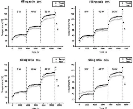
After obtaining the saturation pressure value, the saturation temperature could be calculated using available software. Comparing the saturation temperature data to the evaporator tem-perature data allowed for the estimation of the evaporation phe-nomenon inside thermosyphon. It must be noted that the evaporation phenomenon only occurs when the evaporator tem-perature surpasses the saturation temtem-perature. The relationship between these temperatures in the thermosyphon at the predeter-mined filling ratios is depicted inFig. 9. As shown, at most filling ratio variations, the evaporator temperature remained above the saturation temperature shortly after the application of heating load. This primarily occurred at the 40 W and 96 W heating loads. These results indicate that the thermosyphon worked with two-phase principle and evaporation transpired. An exception occurred when the highly charged thermosyphon received filling ratios of 80% and 90%. For this variation, as shown inFig. 9, evaporation only
occurred after the application of the 40 W heating load. Therefore, the two-phase heat transfer phenomenon is harder to achieve at higher filling ratios.
The relationship between the working fluid filling ratio and the evaporator temperature and pressure is described inFig. 10. The thermosyphon with a 10% filling ratio maintained the smallest
amount of working fluid and caused the thermosyphon to have the lowest effective heat capacity,ceff. When heat was applied at
a predetermined amount, the sensible heat was used to increase the temperature of both the thermosyphon and the working fluid. Because the ceff was small, the temperature rose quickly and
reached the saturation temperature of the working fluid. The fluid evaporated and expanded, filling up the vapor space and causing the pressure to rise abruptly. Due to the saturation pressure increase, the saturation temperature also escalated and caused the evaporator temperature to rise, as well.
Meanwhile, at the 70% filling ratio, more working fluid caused a higher heat capacity. This, in turn, produced more heat to be absorbed and increased the working fluid temperature to instigate phase change. The fluid in the vapor phase rushed up to the con-denser and filled the empty vapor space. It then condensed and flo-wed back into the evaporator. The vapor circulation kept the pressure and temperature comparatively low.
At the 90% filling ratio, virtually all of the heat absorbed by the working fluid caused its temperature to escalate. When the sat-uration temperature was reached, the working fluid evaporated within an insufficient amount of vapor space. With this limited vapor expansion space, the evaporation rate in the evaporator was decreased. The decrease of evaporation rate meant that the heat absorbed as sensible heat, unlike the latent heat phase-chang-ing heat at constant temperature, increased the evaporator tem-perature. This finding substantiates the study conducted by Naphon et al.[27,28].
Fig. 6.Experimental setup of neutron radiography.
Fig. 7.Effect of filling ratio to evaporator temperature for various heating loads.
Table 1
Evaporator temperature at various heating load and filling ratio.
Filling ratio 10% 20% 30% 40% 50% 60% 70% 80% 90% Heat load (W) Evaporator temperature (degree Celcius)
3.2. Analysis of neutron radiography image
Fig. 11 displays the schematic of a heat pipe sample having undergone neutron radiography. As illustrated, the fan-generated airflow originated on the right side of the setup and the neutron beam propagated normally across the pipe. The transparent alu-minum enclosure exposed the pool of working fluid at the
evaporator, as shown by a dark area in the figure. The capillary pipe made of stainless steel has a higher attenuation level than alu-minum and results in a darker image. The dark zone at the upper side of the evaporator is a temperature resistant chemical bond. All the radiography images have exposure time of 4 s and spatial resolution of 100
l
m.The image result of neutron radiography was analyzed by image processing software, ImageJ 1.47v; these results are shown in
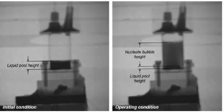
Fig. 11. The dark zone imagery shows the fluid locations inside the heat pipe, as do the gray level measurements, regardless of if the fluid is in a liquid or vaporous state. Image digitation was per-formed via an 8-bit image with the pixel gray level ranging from 0 to 255 and higher values indicate brighter pixel measures. A dark zone inside the sample with maximum gray level below 60 is con-sidered as working fluid in liquid state. It appeared inside the sam-ple at the bottom part, in a large amount at initial condition, and in small fraction at operating condition. The zone considered as the working fluid liquid pool. The distance from the inner-bottom part of heat pipe to the upper part of this dark zone was measured and quantified as liquid pool height, as shown inFig. 12. Meanwhile at operating condition, a lighter dark zone (gray level of 90–150) appeared at the upper surface of the liquid pool. It is considered as the bubble produced from nucleation, and rise to the upward direction. The distance from the upper surface of liquid pool to the upper part of nucleate bubble was measured and quantified as nucleate bubble height. In the further section, the nucleate bub-ble height is used to proportionally represent the intensity of the bubble generation. For the sectional gray level measurement, the
Fig. 8.Pressure and filling ratio inside the thermosyphon.
heat pipe was divided into three sections as follows: the evap-orator, the adiabatic and the condenser. The condenser is further divided into three segments one condenser segment and two capil-lary pipe segments, as shown inFig. 13.
3.3. Working fluid circulation in the thermosyphon and heat pipe
This study conducted neutron radiography imagery of two pas-sive heat exchangers, the thermosyphon and the heat pipe. The
Fig. 10.Relationship between filling ratio, vapor space and pressure inside the thermosyphon.
main difference between these two devices was the manner in which working fluid was circulated from the condenser to the evaporator. Unlike a wickless thermosyphon that used gravity to circulate a working fluid, the heat pipe used the capillary force pro-vided by the wick structure. The differences in the working princi-ple affecting fluid circulation inside these two heat exchangers; the circulation was captured by neutron radiography, as shown in
Fig. 14.
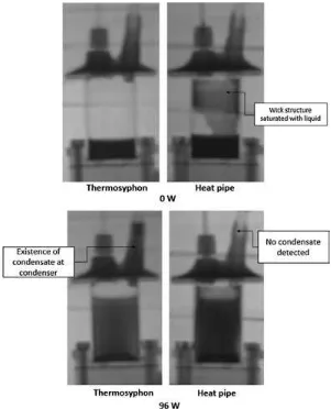
Fig. 14shows both the thermosyphon and the heat pipe with the heating loads applied at 0 W and 96 W. Even at the 0 W load application, the heat pipe wick structure was saturated, as indi-cated by the darker area of the adiabatic and condenser section. Meanwhile, at the application of a 96 W heating load, the main dif-ference in the two structures is the existence of condensate at the condenser. In the thermosyphon, the application of a 96 W heating load produced a small amount of fluid condensate at the con-denser, indicated by the dark area seen both inFig. 14 and by the gray level measurement. Finally, at the application of an
identical heating load to the heat pipe, no condensate was detected. No condensate was visually detected, and there was no significant change in the gray level measurement at the condenser section.
These outcomes indicate that the wick structure effectively worked as a fluid circulation media. The nonexistence of a wick structure in the thermosyphon caused condensate built up at the condenser; condensate then could not be rapidly circulated to the evaporator. The condensate in the thermosyphon took to become heavy enough to gather after falling down and returning to the evaporator. The vapor pressure obstructed the condensate flow from the evaporator. This phenomenon caused the conden-sate to gather at that location, as shown inFig. 14. A dissimilar sit-uation ensued at the heat pipe, however. The existence of the wick structure caused the condensate to return instantaneously to evap-orator and was undetectable by radiography imagery.
3.4. Variation of heating load to boiling-evaporation phenomenon
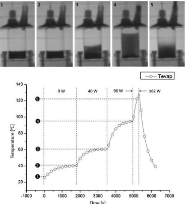
In this section, visualization using neutron radiography was conducted on both the thermosyphon and the heat pipe. Heating loads of 9 W, 40 W and 96 W were applied. A load of 162 W was also applied to the thermosyphon and heat pipe for a short period of time to achieve a picture of the boiling-evaporation phe-nomenon while operating under incredibly high heat flux. The radiography result is displayed inFigs 15–17, and the quantitative data of corresponding image is listed inTables 2 and 3.
Fig. 15shows the results of the thermosyphon sample with 20% working fluid and a 5 kPa vacuum in the chamber. Meanwhile,
Table 2 shows the value of the working liquid pool height, the nucleate bubble height and the gray level of each section of the thermosyphon, referencing to Fig. 15 and Table 2show that at the application of a 9 W heating load (image number 2), evap-oration ensued. The evapevap-oration shown by the decrease of both the liquid pool height and the gray level at the condenser section were related to the existence of fluid at condenser. At this heating load value, boiling did not occur, and bubbles were not generated. At the application of the 40 W heating load (image number 3), the height of liquid pool decreased further from 1.3 cm to 1.02 cm. Boiling began at this point, as indicated by the existence of nucle-ate bubble, a gradation of gray zone above the liquid pool. The height was measured at 1.02 cm from the surface of liquid pool. The condensate increased, revealed by the further decrement of the gray level at the condenser section from 120 to 116. Boiling occurred more violently at the application of the 96 W heat load
Fig. 12.Quantitative measurement of boiling phenomenon in the terms of liquid pool and nucleate bubble height at initial and operating condition.
(image number 4). This indicated further decrement of the liquid pool to 0.54 cm; the nucleate bubble height increased further to 3.61 cm. Condensate was gathered with greater volume at the con-denser, shown by a smaller gray level of 111. Bubble generation and the condensate are both seen in.
In a short application of the 162 W heat load (image number 5), the liquid pool height increased while the nucleate bubble height decreased. These findings indicate that boiling intensity dimin-ished at application of very high heat flux. However, the evap-oration continued to occur at high intensity, as indicated by a decrement of the gray level to 105 at the condenser section. Additionally, the results clearly show greater condensate accumu-lation at the condenser during this period.
Meanwhile,Fig. 17indicates the radiography result of the heat pipe sample. The heat pipe was water-charged with 20% filling ratio and vacuumed to 5 kPa.Table 3shows the height of liquid pool, the nucleate boiling height and the gray level of the entire heat pipe section. Fig. 17 further displays a light area at the lower-left portion of the heat pipe, above the liquid pool surface. This area is assumed to be a part of the setup not enclosed by the wick structure and detached from the heat pipe wall.
FromFig. 17, it can be inferred that the application of a 9 W heating load to the heat pipe produced a quiet evaporation, shown by the nonexistence of a nucleate bubble above the liquid pool. Evaporation was detected by the decrement of the gray level at
the condenser, from 107 to 103, indicating the existence of conden-sate. It may be seen inTable 3that the application of a 9 W heat load resulted in the existence of fluid at the adiabatic section. These findings assumed a condensate flow back to the condenser from the evaporator via the wick structure. At the application of a 40 W heating load, boiling began; at the application of the 96 W heating load, boiling ensued more intensely. The liquid pool height was 1.33 cm and 0.48 cm, and the nucleate bubble height from the liquid surface was 0.61 and 3.58 for the application of a 40 W and 96 W heating load, respectively. At the condenser, there was no significant change in the gray level measurement, indicat-ing no condensate remainindicat-ing in the heat pipe.
Once again, at the short application of a 162 W heating load, a decrease in boiling intensity was found, indicated by the decrease of the nucleate boiling height, from 3.58 cm to 1.9 cm. The liquid pool height also increased to 1.05 cm. The gray level at the con-denser did not change significantly during this phase of experimentation.
As inferred by the radiography visualization testing results, both the thermosyphon and the heat pipe show an identical boil-ing-evaporation phenomenon. Fig. 8, depicts the application of higher heat flux resulting in higher pressure inside the heat pipe. Higher pressure leads to higher saturation temperature, producing evaporation at higher temperature. At the application of a 9 W heating load, the fluid temperature has surpassed the saturation
temperature; however, the temperature was not high enough to commence the nucleate bubble generation. This generation caused the phase change phenomenon to remain relatively static without the occurrence of boiling. At the application of a 40 W heating load, fluid temperature reached a value high enough to begin bubble generation. Boiling thus occurred and a bubble was detected. At the application of a 96 W heating load, the fluid had a higher tem-perature value, causing rapid boiling and the formation of a large nucleate bubble.
Finally, at the application of a 162 W heating load, the fluid temperature has a very high temperature. The pressure, however, of heat pipe at the 162 W heating load became so high that the sat-uration temperature was also extremely elevated. This led to the reduction of boiling phenomenon, resulting in the decrease of the nucleate bubble height. These findings confirm previous findings from research conducted by Wong and Kao[35]in which they sta-ted that there is no boiling phenomenon both at the very low and very high heat fluxes.
3.5. Effect of pressure
The study on effect of pressure was conducted using heat pipe sample. Heat pipe samples were used with the same filling ratio
and work under same heating load for this section of research; however, different initial pressures,po, were used. The first sample
was set to atmospheric pressure at 101.3 kPa; meanwhile, the sec-ond sample was given a vacuum pressure of 5 kPa. The comparison of the boiling-evaporation phenomenon of the two samples is shown in Fig. 18. From the figure, it is realized that boiling did not occur on the sample at atmospheric pressure and no nucleate bubble formed above the surface of the liquid pool. Static evap-oration was determined from the existence of condensate at the condenser, especially at the application of a 96 W heating load. Meanwhile, in the heat pipe operating with the vacuum at atmo-spheric pressure, boiling was observed after the application of a 40 W heating load. This phenomenon was identified by the exis-tence of a gray zone above the liquid pool, and it again becomes proof that boiling is harder to achieve in a high-pressure environ-ment due to higher saturation temperatures. Finally, in the reduced pressure environment, the liquid temperature surpassed the low saturation temperature and induced boiling.
Those findings agrees in some way with the research conducted by McGillis, et al.[44,45]. McGillis, et al. compared the nucleate boiling data from three different pressure which are 4 kPa, 9 kPa, and 101 kPa. Instead of using closed system as used in this study, McGillis tested the boiling phenomenon at a controlled pressure
system. The study shows that although the reduction in pressure for saturated water system shifted the boiling curve to higher wall superheat level, the decrease in saturation temperature due to lower pressure compensate the effect. Therefore, lower system pressure leads to lower wall temperature for a given heat flux. The lower pressure also lower vapor densities, larger bubble diameter and decrease the minimum heat input required for nucle-ation to happen.
Comparing to the of McGillis’s, the result of this recent study could not show the increase of superheat that required for nucle-ation. However both studies show that, for lower system pressure, the nucleation achieved at lower heat input. Both also shows that, in reduced pressure environment, bubble grows with larger breadth and higher intensity.
3.6. Steady boiling-evaporation phenomenon
The study on boiling-evaporation phenomenon was conducted using heat pipe sample. To determine the phenomenon of boil-ing-evaporation inside a heat pipe at steady state, a heating load of 96 W was applied for 100 min to heat pipe samples under initial vacuum pressure conditions. The fluid, water, was added to the sample with a filling ratio of 20%. The neutron radiography ima-gery captured sequential images of the heat pipe temperature rise
Fig. 16.Visual investigation of radiography result.
while the pipe was in a transient state until the temperature was steady, as depicted inFig. 19.
The figure shows the beginning of temperature raise when the nucleate bubble was generated at 65°C (image number 3). Along
with the temperature raise, boiling transpired more intensely while the nucleate bubble size increased. The maximum nucleate bubble height observed at the temperature of 105°C (image
num-ber 7) showed a maximum height,hmax, of 3.88 cm. However, when
the rate of temperature change slowed, it was discovered that when the temperature increased from 105°C to 115°C in 60 min,
the height of nucleate bubble also gradually decreased and reached the minimum height of 0.55 cm.
This phenomenon cannot be attributed to the incremental increase of pressure inside heat pipe, however, as the data shown in Fig. 19 indicates, the evaporator temperature occurred at a higher value than the saturation temperature. Thus, the condition always fulfills the requirements to induce boiling. The phe-nomenon may be explained by the heat absorbed by the fluid to elevate its temperature, as shown by numbers 1–2 in Fig. 19. When the fluid reached the conditions to induce boiling and develop a bubble as shown by numbers 3–7 in the same figure, large amounts of fluid changed phase from liquid to vapor and grew into a nucleate bubble. This transient boiling created a large and intense bubble, rushing to fill the evacuated space and reach-ing maximum height. When the rate of temperature increase began to decrease and the heat pipe began to operate at a steady condition, vapor filled the once evacuated space. The vapor-filled space maintained adequate pressure to suppress the bubble
Table 2
Gray level measurement and height of the liquid pool and nucleate bubble generation.
Table 3
Gray level measurement and height of liquid pool and nucleate bubble generation.
generation so the nucleate bubble height decreased and reached its minimum height. At the condenser, condensate then circulated back to the evaporator. In this final state, heat pipe operation was complete.
4. Conclusion
There are a number of conclusions resulting from this research, as follows:
– Pressure measurement plays an important role in supplying information about evaporation and the heat transfer phenomenon inside of a heat pipe. The pressure value may be used to determine the saturation temperature to further determine the superheated condition at the evaporator.
– An optimum value of working fluid filling ratio exists as related to heat capacity and vapor space inside a heat pipe.
– Neutron radiography could be used as a visualization technique for heat transfer phenomenon and liquid circulation examina-tion inside a heat pipe. Using neutron radiography, it was dis-covered that static evaporation occurred at the application of both very low and a very high heat flux. At reduced pressure, a nucleate bubble developed with larger size and greater inten-sity due to low vapor deninten-sity.
– In a steady-state heat pipe, boiling occurred at low intensity due to the existence of vapor filling the evacuated space, which sup-pressed the development of the nucleate bubble.
– Neutron radiography showed the functionality of the wick structure as a circulator of the working fluid.
Acknowledgment
The authors would like to thank the DRPM University of Indonesia for funding this research through research cluster program.
References
[1]Y.-S. Chen, K.-H. Chien, T.-C. Hung, C.-C. Wang, Y.-M. Ferng, B.-S. Pei, Numerical simulation of a heat sink embedded with a vapor chamber and calculation of effective thermal conductivity of a vapor chamber, Appl. Therm. Eng. 29 (2009) 2655–2664.
[2]W.N. Septiadi, N. Putra, M. Juarsa, I.P.A. Putra, R. Sahmura, Characteristics of screen mesh wick heat pipe with nano-fluid as passive cooling system, Atom Indones. 39 (2013) 24–31.
[3]S.-S. Hsieh, R.-Y. Lee, J.-C. Shyu, S.-W. Chen, Analytical solution of thermal resistance of vapor chamber heat sink with and without pillar, Energy Convers. Manage. 48 (10) (2007) 2708–2717.
[4]H.N. Chaudhry, B.R. Hughes, S.A. Ghani, A review of heat pipe system for heat recovery and renewable energy applications, Renew. Sustain. Energy Rev. 16 (2012) 2249–2259.
[5]M. Reyes, D. Alonso, J.R. Arias, A. Velazquez, Experimental and theoretical study of a vapour chamber based heat spreader for avionics applications, Appl. Therm. Eng. 37 (2012) 51–59.
[6]P. Naphon, S. Wiriyasart, Study on the vapor chamber with refrigerant R-141b as working fluid for HDD cooling, Int. Commun. Heat Mass Transfer 39 (9) (2012) 1449–1452.
[7]P. Naphon, S. Wongwises, S. Wiriyasart, Application of two-phase vapor chamber technique for hard disk drive cooling of PCs, Int. Commun. Heat Mass Transfer 40 (2013) 32–35.
[8]J.-C. Wang, Thermal investigations on LED vapor chamber-based plates, Int. Commun. Heat Mass Transfer 38 (9) (2011) 1206–1212.
[9]J.-C. Wang, R.-T. Wang, T.-L. Chang, D.-S. Hwang, Development of 30 Watt high-power LEDs vapor chamber-based plate, Int. J. Heat Mass Transf. 53 (19– 20) (2010) 3990–4001.
[10]N. Putra, Design, manufacturing and testing of a portable vaccine carrier box employing thermoelectric module and heat pipe, J. Med. Eng. Technol. 33 (3) (2009) 232–237.
[11]N. Putra, Adriansyah, W. Sukyono, D. Johansem, F.N. Iskandar, The characterization of a cascade thermoelectric cooler in a cryosurgery device, Cryogenics 50 (11–12) (2010) 759–764.
[12]N. Putra, R. Saleh, W.N. Septiadi, A. Okta, Z. Hamid, Thermal performance of biomaterial wick loop heat pipes with water-base Al2O3nanofluids, Int. J.
Therm. Sci. 76 (2014) 128–136.
[13]C.-C. Yeh, C.-N. Chen, Y.-M. Chen, Heat transfer analysis of a loop heat pipe with biporous wicks, Int. J. Heat Mass Transf. 52 (19–20) (2009) 4426–4434. [14]D. Deng, D. Liang, Y. Tang, J. Peng, X. Han, M. Pan, Evaluation of capillary
performance of sintered porous wick for loop heat pipe, Exp. Thermal Fluid Sci. 50 (2013) 1–9.
[15]Z. Ming, L. Zhongliang, M. Guoyoan, The experimental and numerical investigation of a grooved vapor chamber, Appl. Therm. Eng. 29 (2–3) (2009) 422–430.
[16]X. Ji, J. Xu, A.M. Abanda, Copper foam based vapor chamber for high heat flux dissipation, Exp. Thermal Fluid Sci. 40 (2012) 93–102.
[17]R. Saleh, N. Putra, S.P. Prakoso, W.N. Septiadi, Experimental investigation of thermal conductivity and heat pipe thermal performance of ZnO nanofluids, Int. J. Therm. Sci. 63 (2013) 125–132.
[18]N. Putra, W.N. Septiadi, H. Rahman, R. Irwansyah, Thermal performance of screen mesh wick heat pipes with nanofluids, Exp. Thermal Fluid Sci. 40 (2012) 10–17.
[19]S.-C. Wong, S.-F. Huang, K.-C. Hsieh, Performance tests on a novel vapor chamber, Appl. Therm. Eng. 31 (10) (2011) 1757–1762.
[20]A.A.A. Attia, B.T.A. El-Assal, Experimental investigation of vapor chamber with different working fluids at different charge ratios, Ain Shams Eng. J. 3 (3) (2012) 289–297.
[21]P. Naphon, S. Wongwises, S. Wiriyasart, Application of two-phase vapor chamber technique for hard disk drive cooling of PCs, Int. Commun. Heat Mass Transfer 40 (2013). pp. 32.25.
[22]T. Sukchana, C. Jaiboonma, Effect of filling rations and adiabatic length on thermal efficiency of long heat pipe filled with R-134a, Energy Proc. 34 (2013) 298–306.
[23]S. Lips, F. Lefevre, J. Bonjour, Combined effects of the filling ratio and the vapour space thickness on the performance of a flat plate heat pipe, Int. J. Heat Mass Transf. 53 (2009) 694–702.
[24]H.M.S. Hussein, H.H. El-Ghetany, S.A. Nada, Performance of wickless heat pipe flat plate solar collectors having different pipes cross sections geometries and filling ratios, Energy Convers. Manage. 47 (2006) 1539–1549.
[25]K.S. Ong, Md. Haider-E-Alahi, Performance of a R-134a-filled thermosyphon, Appl. Therm. Eng. 23 (2003) 2373–2381.
[26]Y.-H. Lin, S.W. Kang, Effect of silver nano-fluid on pulsating heat pipe thermal performance, Appl. Therm. Eng. 28 (2008) 1312–1317.
[27]P. Naphon, P. Assadamongkol, T. Borirak, Experimental investigation of titanium nanofluids on the heat pipe thermal efficiency, Int. Commun. Heat Mass Transfer 35 (2008) 1316–1319.
[28]P. Naphon, D. Thongkum, P. Assadamongkol, Heat pipe efficiency enhancement with refrigerant-nanoparticles mixtures, Energy Convers. Manage. 50 (2009) 772–776.
[29]S.-C. Wong, C.-W. Chen, Visualization and evaporator resistance measurement for a groove-wicked flat-plate heat pipe, Int. J. Heat Mass Transf. 55 (9–10) (2012) 2229–2234.
[30] S.-C. Wong, C.-W. Chen, Visualization experiments for groove-wicked flat-plate heat pipes with various working fluids and powder-groove evaporator, Int. J. Heat Mass Transf. 66 (2013) 396–403.
[31]Y.S. Lim, S.C.M. Yu, N.T. Nguyen, Flow visualization and heat transfer characteristics of gas–liquid two-phase flow in microtube under constant heat flux at wall, Int. J. Heat Mass Transf. 56 (1–2) (2013) 350–359. [32]S.-C. Wong, H.-H. Tseng, S.-H. Chen, Visualization experiments on the
condensation process in heat pipe wicks, Int. J. Heat Mass Transf. 68 (2014) 625–632.
[33]J.-H. Liou, C.-W. Chang, C. Chau, S.C. Wong, Visualization and thermal resistance measurement for the sintered mesh-wick evaporator in operating flat-plate heat pipe, Int. J. Heat Mass Transf. 53 (7–8) (2010) 1498–1506. [34]S.-C. Wong, J.-H. Liou, C.-W. Chang, Evaporation resistance measurement with
visualization for sintered copper-powder evaporator in operating flat-plate heat pipes, Int. J. Heat Mass Transf. 53 (19–20) (2010) 3792–3798. [35]S.-C. Wong, Y.-H. Kao, Visualization and performance measurement of
operating mesh-wicked heat pipes, Int. J. Heat Mass Transf. 51 (2008) 4249– 4259.
[36]K. Sugimoto, H. Asano, H. Murakawa, N. Takenaka, T. Nagayusu, S. Ipposhi, Evaluation of liquid behavior in a variable conductance heat pipe by neutron radiography, Nucl. Instrum. Meth. Phys. Res. A 651 (2011) 264–267. [37] M.N. Dawson, Applications of Neutron Radiography & Tomography, The
University of Leeds School of Physics & Astronomy, Disertasi, 2008. [38]K.T. Mishima, T. Hibiki, H. Nishihara, Visualization and measurement of
two-phase flow by using neutron radiography, Nucl. Eng. Des. 175 (1–2) (1997) 25– 35.
[39]K. Uchimura, G.D. Harvel, T. Matsumoto, M. Kanzaki, J.-S. Chang, An image processing approach for two-phase interfaces visualized by a real time neutron radiography technique, Flow Meas. Instrum. 9 (4) (1998) 203–210. [40] N. Takenaka, T. Fujii, K. Akagawa, A. Ono, K. Sonoda, K. Nishizaki, H. Asano,
Application of neutron radiography to visualization of multiphase flows, Flow Meas. Instrum. 1 (3) (1990) 149–156.
[41]H. Asano, N. Takenaka, T. Fujii, Y. Shibata, T. Ebisu, M. Matsubayashi, Visualization and measurement of refrigerant flow in compression-type refregerator by neutron radiograpy, Nucl. Instrum. Methods Phys. Res., Sect. A 424 (1) (1999) 98–103.
[42]B. Borgmeyer, Heat transport capability and fluid flow neutron radiography of three-dimensional oscillating heat pipes, Heat Transf. 2 (1) (2008) 4. [43] M.N. Dawson, PhD Thesis, University of Leeds, UK, May 2008.
[44] W.R. McGillis, J.S. Fitch, W.R. Hamburgen, V.P. Carey, Pool boiling enhancement techniques for water at low pressure, The Western Research Laboratory (WRL) Research Report 90/9, 1990.
Visualization of the boiling
phenomenon inside a heat pipe
using neutron radiography
by
Wayan Nata Septiadi
FILE
TIME SUBMITTED
10-JUL-2015 06:00AM
SUBMISSION ID
554905461
WORD COUNT
7715
CHARACTER COUNT
39717
6
%
SIMILARITY INDEX
3
%
INTERNET SOURCES
5
%
PUBLICATIONS
2
%
STUDENT PAPERS
1
2
%
2
<
1
%
3
<
1
%
4
<
1
%
5
<
1
%
6
<
1
%
Visualization of the boiling phenomenon inside a heat pipe
using neutron radiography
ORIGINALITY REPORT
PRIMARY SOURCES
Submitted to Higher Education Commission
Pakistan
Student Paper
Putra, Nandy, Wayan Nata Septiadi, Rosari
Saleh, Rardi Artono Koestoer, and Suhendro
Purbo Prakoso. "The Effect of CuO-Water
Nanofluid and Biomaterial Wick on Loop
Heat Pipe Performance", Advanced Materials
Research, 2014.
Publication
decdoc.itsx.net
Internet Source
www.thermalfluidscentral.com
Internet Source
thermalfluidscentral.com
Internet Source
Ju Dong Lee. "Dynamics of
Methane−Propane Clathrate Hydrate Crystal
Growth from Liquid Water with or without the
Presence of
n
-Heptane", Crystal Growth &
7
<
1
%
8
<
1
%
9
<
1
%
10
<
1
%
11
Publication
Sugimoto, K.. "Evaluation of liquid behavior
in a Variable Conductance Heat Pipe by
neutron radiography", Nuclear Inst. and
Methods in Physics Research, A, 20110921
Publication
Alawi, Omer A., Nor Azwadi Che Sidik, H.A.
Mohammed, and S. Syahrullail. "Fluid flow
and heat transfer characteristics of
nanofluids in heat pipes: A review",
International Communications in Heat and
Mass Transfer, 2014.
Publication
Solomon, A. Brusly, R. Roshan, Walter
Vincent, V.K. Karthikeyan, and L. Godson
Asirvatham. "Heat transfer performance of
an anodized two-phase closed thermosyphon
with refrigerant as working fluid",
International Journal of Heat and Mass
Transfer, 2015.
Publication
Kwark, Sang M., Miguel Amaya, and Seung
M. You. "Pool boiling heat transfer
characteristics of nanocoating in various
working fluids", 2011 27th Annual IEEE
Semiconductor Thermal Measurement and
Management Symposium, 2011.
Publication
<
1
%
12
<
1
%
13
<
1
%
14
<
1
%
15
<
1
%
16
<
1
%
17
<
1
%
for two-phase interfaces visualized by a real
time neutron radiography technique", Flow
Measurement and Instrumentation, 199812
Publication
www.iosrjournals.org
Internet Source
Ji, Yulong, Gongwei Liu, Hongbin Ma, Gen Li,
and Yuqing Sun. "An experimental
investigation of heat transfer performance in
a polydimethylsiloxane (PDMS) oscillating
heat pipe", Applied Thermal Engineering,
2013.
Publication
www.nanoscalereslett.com
Internet Source
waset.org
Internet Source
Mancin, Simone, Claudio Zilio, Andrea Diani,
and Luisa Rossetto. "Air forced convection
through metal foams: Experimental results
and modeling", International Journal of Heat
and Mass Transfer, 2013.
Publication
Hassan, Hamdy, and Souad Harmand.
"Parametric Study of the Effect of the Vapor
Chamber Characteristics on Its Performance",
Journal of Heat Transfer, 2013.
18
<
1
%
19
<
1
%
20
<
1
%
21
<
1
%
22
<
1
%
23
<
1
%
Wong, S.C.. "Visualization and evaporator
resistance measurement for a groove-wicked
flat-plate heat pipe", International Journal of
Heat and Mass Transfer, 201204
Publication
Sungkar, Ali A., Firman Ikhsan, M. Afin
Faisol, and Nandy Putra. "Performance of
Thermoelectrics and Heat Pipes
Refrigerator", Applied Mechanics and
Materials, 2013.
Publication
www.ipcsit.com
Internet Source
Naphon, P.. "On the performance of air
conditioner with heat pipe for cooling air in
the condenser", Energy Conversion and
Management, 201011
Publication
Putra, N.. "Thermal performance of screen
mesh wick heat pipes with nanofluids",
Experimental Thermal and Fluid Science,
201207
Publication
Cao, Y., M. Gao, J. E. Beam, and B. Donovan.
"Experiments and Analyses of Flat Miniature
Heat Pipes", Journal of Thermophysics and
Heat Transfer, 1997.
24
<
1
%
25
<
1
%
26
<
1
%
27
<
1
%
28
<
1
%
Stubblebine, Michael J., and Ivan Catton.
"Passivation and Performance of Inorganic
Aqueous Solutions in a Grooved Aluminum
Flat Heat Pipe", Journal of Heat Transfer,
2015.
Publication
Liang, Shibin. "Oscillating Characteristics of
Slug Flow in Oscillating Heat Pipes", 9th
AIAA/ASME Joint Thermophysics and Heat
Transfer Conference, 2006.
Publication
Léal, L., M. Miscevic, P. Lavieille, M.
Amokrane, F. Pigache, F. Topin, B.
Nogarède, and L. Tadrist. "An overview of
heat transfer enhancement methods and new
perspectives: Focus on active methods using
electroactive materials", International Journal
of Heat and Mass Transfer, 2013.
Publication
Idrus, Fairosidi, Nazri Mohamad, Ramlan
Zailani, Wirachman Wisnoe, and Mohd
Zulkifly Abdullah. "Thermal Performance of a
Cylindrical Heat Pipe for Different Heat
Inputs and Inclination Angles", Applied
Mechanics and Materials, 2014.
Publication
EXCLUDE QUOTES
OFF
EXCLUDE
BIBLIOGRAPHY
ON
EXCLUDE MATCHES
OFF
nanofluids for heat transfer applications",
Experimental Thermal and Fluid Science,
2013.