Frequency-Tunable Electromagnetic Energy
Harvester by means of Damping Switching
B.L. Ooi
Faculty of Integrative Sciences & Technology Quest International University Perak Jalan Raja Permaisuri Bainun, 30250,
Ipoh Perak, Malaysia. benglee [email protected]
J.M. Gilbert
School of EngineeringUniversity of Hull, Hull, HU6 7RX, United Kingdom. [email protected]
A. Rashid A. Aziz
Center for Automotive Research Universiti Teknologi PETRONASBandar Seri Iskandar, 31750, Tronoh, Perak, Malaysia. [email protected]
Abstract—In this paper, a switching damping system that can widen the operational bandwidth of an electromagnetic vibration energy harvester is presented. In the system, the damping is switched periodically within each oscillation cycle in response to the real-time position and velocity of the devices resonator. A comprehensive timing model of switching damping device is derived analytically and its resonant frequency is computed by using the MATLAB solver. The simulated results demonstrate that natural frequency of the system can be shifted up or down for a reasonably range of natural frequency by switching the electrical induced damping. The results also indicate that for a higher damping system, the devices natural frequency can be shifted up to the range of +20.2% and -58.6% away from the initial natural frequency. However, the drawback is that the switching damping system will affects the peak output, which is highly dependent on the value of the damping.
Keywords—Electromagnetic generator, Wideband energy har-vester, Switching damping, Frequency tuning
I. INTRODUCTION
Over the past decade, due to the decreasing power require-ment and device sizes of electronic sensors, energy harvesting technologies have attracted a great interests from many aca-demician and research parties [1] across the world who seek an alternative power source so that batteries can be replaced permanently, and thus sustainable sensor devices with the capa-bility of self-powering can be achieved. Many different forms of energy can be harvested from the ambient environment, such as solar, wind, thermal, radio wave and vibration [2]. Due to the availability of vibration energy in most of the targeted sensor system applications, this type of energy has attracted considerable research interest [3]. Vibration energy is available in most built environments. The energy that can be extracted from a vibration source depends on the amplitude of the vibration and its frequency. Vibration sources vary considerably in amplitude and dominant frequency. Roundy [4] presented the results for the measurement of a number of vibration sources which indicate that the amplitude and frequency varies from 12 ms-2 at 200 Hz for a car engine compartment to 0.2 ms-2 at 100 Hz for the floor in an office building with the majority of sources measured having a fundamental frequency in the range of 60-200 Hz. This implies that the available environmental vibration is typically made up by a number of fundamental frequencies. For example,
the vibration spectrum given in Fig. 1 which is measured from a domestic freeze, indicates a fundamental frequency of 50 Hz with an acceleration amplitude of 0.1 ms-2. The available energy that can be extracted from the vibration depends on the source frequency and amplitude. Hence, it is important to design the harvester with a resonance mode that matches the source dominant frequency to achieve a greater performance.
Although a number of linear vibration-to-electricity type of harvesters have been proposed in the literature by different group of researcher, there exist a continuing challenges that prevents widespread application of vibration-based energy harvester such as limited operational bandwidth [5] of the device. Most of the vibration-based harvester devices are only able to convert kinetic energy into electrical energy optimally when the system natural frequency is matched with the environmental vibration excitation at the location, where harvester is implemented. When the dominant frequency of the environment changes, the output generated from the device will drops significantly and may not be sufficient to power the sensor device for usual operation. It is also noteworthy to highlight that the frequency of the dominant vibration mode is highly dependent on the operating parameters of the equipment causing the vibration. For example, the frequencies present in a car engine compartment will depend on the speed of the engine and the loading on the vehicle. The frequencies present in a particular location may not be well known or may vary over time and so there have been many attempts to develop energy harvesting devices with a wider frequency response than achieved with a simple linear oscillator or capable of being tuned, or of tuning themselves to the ambient vibration.
Many strategies have been proposed and investigated, in-cluding frequency tuning [6], external magnetic effect [7], multi-array generators [8], Non-linear oscillation [9] and dual-resonator [10], [11]. Most of these tuning solutions for fre-quency matching problem have been well-documented by Beeby et al. [12] and Tang et al. [13]. However, all the proposed methods either with a fixed range of tunable resonant frequency or require physical adjustment to the hardware, no report has yet been published on tuning the dominant frequent of harvester devices by means of changing the effective electrical induced damping digitally in real-time at different oscillating quadrants when the device is under the force of external vibration excitation.
2015 International Conference on Automation, Cognitive Science, Optics, Micro Electro-Mechanical System, and Information Technology (ICACOMIT), Bandung, Indonesia, October 29–30, 2015
Fig. 1. Vibration spectrum for a domestic freeze, a) magnitude of acceleration and b) magnitude of displacement
In this paper, different values of electrical induced damping are applied to the system at various quadrants cycle. This allows adjustment of the natural frequency above or below the initial resonance for the fixed damping system. A fundamental model of a fixed damping energy converter system is presented, which is followed by the derivation and description of a switching damping system. The predicted natural frequen-cies for various damping coefficient for a switching systems are analytically calculated and compared among themselves together with the natural frequency of a conventional fixed damping system. Lastly, discussion and conclusion are also made according to the results captured from the analytical solution.
II. BASICTHEORY
Vibration energy harvesting devices are generally modeled as mass, spring, damper systems as illustrated in Fig. 2 [14]. The system comprises of a seismic mass,m, and a spring of stiffness, k. The seismic mass is suspended within the outer case and the entire device moves relative to the inertial frame with the position of the case at time,t, described byu(t). The position of the seismic mass relative to its equilibrium position within the case isx(t). The total losses within the system and energy successfully extracted from the motion are represented by the damper. The characteristics of this damping element depend on the type of energy conversion utilized but if the damping force is assumed to be proportional to the system velocity, x˙(t), with viscous damping coefficient, b, then the equations of motion may be written as:
mx¨(t) +bx˙(t) +kx(t) =−mu¨(t) (1)
A commonly investigated electromagnetic conversion de-vice, is comprised of a moving magnet attached to the free end and a pick-up coil fixed at the base. When an external vibration excitation force is applied, the relative motion is created between the magnetic field, B from the magnets and the coil. Based on the electromagnetic induction, the induce voltage is given as:
Vg(t) =Kex˙(t) (2)
whereKe=nBlis the emf constant,nis the number of turns in the pick-up coil andlis the practical effective mean length of the coil that perpendicularly cuts through theBfield during the oscillation. Assuming a coil resistance,Rc, and that a load resistance,RL, is connected to the device, the voltage delivers to the load resistance is:
VL= (RLVg)/(Rc+RL) (3)
and the current flowing through the coil and resistive load is:
iL=Vg/(Rc+RL) (4)
The electromechanical coupling force caused by the current is Fe= Kti(t), where Kt is the force constant and Kt =Ke. Combining these equations and (1) gives:
mx¨(t) + (bm+be) ˙x(t) +kx(t) =−mu¨(t) (5) where the electrical induced damping coefficient may be given as:
be=Ke 2
/(Rc+RL) (6)
There may also be losses due to hysteresis and eddy currents but these will be assumed constant and lumped together with the parasitic losses included in bm. The losses due to coil resistance may however be affected by the choice of
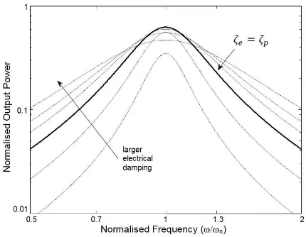
Fig. 3. Relationship between total dissipated power and frequency for vibration resonator
the resistive load resistance. Assuming that the vibration of the device relative to the inertial frame is sinusoidal with u(t) =Usin(ωt), where U is the amplitude of the vibration displacement, then the steady state solution forx(t)is:
x(t) =
"
U ω2 p
[(k/m)2−ω2]2+ (bω/m)2 #
sin(ωt−φ) (7)
The phase angle between the input and seismic mass displace-ment,φis negligible if one is trying to find the maximum avail-able power from the system. By assuming the termsin(ωt−φ)
is maximum, then the available power that dissipates in the damping element can be given as:
Pd=
mζTU2(ω/ωn)3ω3
[1−(ω/ωn)2]2+ [2ζT(ω/ωn)]2
(8)
whereωn= p
k/mis the natural frequency of the system and ζT =ζp+ζe= (bp+be)/2mωn is the damping factor, which can be split into the parasitic element,ζp, representing all the mechanical losses, and the electrical element,ζe, representing available electrical energy to be harvested. The electrical induced damping factor may be given as:
ζe=
Ke 2
2mωn(Rc+RL)
(9)
This implies that the value of damping can be affected by changing the load resistance, RL. For a given amplitude of acceleration, A, the amplitude of the displacement decreases as U =A/ω2
and the average electrical power delivered to the electrical domain can be written as [15]:
Pe=
mζeA 2
(ω2
/ωn 3
) [1−(ω/ωn)2]2+ [2ζT(ω/ωn)]2
(10)
The relationship given in (10) is plotted in Fig. 3 using normalized logarithmic axes for a range of values of electrical damping, ζe. It can be seen that the peak power occurs when the vibration frequency matches the natural frequency
(ω/ωn = 1). It may also be noted that under this condition, the maximum electrical power is generated when the parasitic
and electrical damping element are identical,ζp=ζein which case, the electrical power becomes:
Pe|max= mA2
16ωnζe
(11)
It may also be noted from Fig. 3 that for other frequencies, the maximum electrical energy may occur for other values of ζp < ζe. Thus, if the vibration has a fixed frequency then ζp =ζeis preferable but if the source frequency varies, it may give better average power to use a higher damping factor or to alter the electrical damping in response to changes in source frequency. Equation (11) indicates that the power generated will tend to infinity asζetends to zero. However, this increment is limited by a number of factors. It is not generally possible to reduce the parasitic losses represented byζp to an arbitrarily small value. Also, the amplitude of displacement, x, when operating at ω = ωn is x = U/ζT and so decreasing ζe implies increasing the range of movement which the resonator is capable of making without damage [2].
III. MODELLING OFSWITCHINGDAMPINGENERGY HARVESTINGDEVICE
The analysis above assumes that both the parasitic damping and the extraction of electrical energy result in forces pro-portional to the velocity of the seismic mass. However, it is worthwhile considering the effect that changing the effective electrical damping during the oscillation cycle may have on the behavior of the system. A number of switching regimes may be considered but because the nonlinear system analysis becomes complex, only a simple case will initially be considered. In this proposed regime the electrical damping is switched according to:
be= b
e1 x·x <˙ 0
be2 x·x˙ ≥0
Then (1) can be rewrite in the absence of an input vibration as [16]:
mx¨(t) +kx(t) =−
(b
p+be1) ˙x whenx·x <˙ 0 (12a)
(bp+be2) ˙x whenx·x˙ ≥0 (12b)
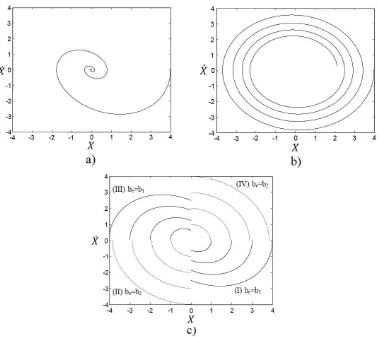
This may conveniently be visualized as phase plan plots as illustrated in Fig. 4 which shows the case for a) higher damping, b) lower damping and c) the switched damping given by (12a) and (12b) forbe1> be2.
To calculate the natural frequency of a switching damping system, the time to complete each quadrant in the oscillation may be calculated. Since the behavior is the same in quadrants I & III and in II & IV, only the model in quadrant I (x >0,x <˙ 0) and quadrant II (x <0,x <˙ 0) will be shown here.
Quadrant I
The behavior in quadrant I is governed by the equation:
Fig. 4. Phase plane plots for switching damping system, a) higher damping, b) lower damping, and c) switched damping
with initial condition ofx(0) =Xo andx˙(0) = 0which may be solved to give:
x(t) =Xoe−ωsζ1t
" ζ1 p
1−ζ12
sintωs p
1−ζ12
+ costωs p
1−ζ12
#
(14)
where the shifted natural frequency, ωs = p
k/m and ζ1 =
(bp+be1)/2ωsm. The trajectory leaves quadrant I whenx(t) =
0 which occurs at a time:
tI =
π−tan−1
hp
(1−ζ12)/ζ1 i
ωs p
1−ζ12
(15)
Quadrant II
The behavior in this case may be treated in a similar manner except thatbe1in (13) is replaced bybe2. The initial conditions
are x(0) = 0 and x˙(0) = ˙Xo. Taking time as starting from
zero, this may be solved to give:
˙
x(t) = ˙Xoe−ωsζ2t "
costωs p
1−ζ22
−p ζ2
1−ζ22
sintωs p
1−ζ22
#
(16)
whereζ2= (bp+be2)/2ωsm. The terminal conditionx˙(t) = 0 occurs at the time:
tII =
tan−1
hp
(1−ζ22)/ζ2 i
ωs p
1−ζ22
(17)
The period,T, for a complete cycle through the four quadrants is:
T = 2(tI+tII) =
2
ωs
π−tan−1
hp
(1−ζ12)/ζ1 i
p
1−ζ12
+ tan −1
hp
(1−ζ22)/ζ2 i
p
1−ζ22
(18)
noted that if ζ1 =ζ2 =ζT, then this simplifies (18) to T =
2π/ωs p
1−ζT2
, which is the period for a system with
fixed damping or ωs = ωn p
1−ζT2, which is the damped natural frequency or shifted frequency in this case.
IV. RESULT ANDDISCUSSION
From the period for a complete cycle (18), one can de-termines the shifted natural frequency for the load switching device by:
ωs= 2π/T (19)
The analysis above does not incorporate the input to the system, u(t), and it has not proved possible to derive a full analytical model for this case, but it is possible to analytically determine the natural frequency given by (18) in MATLAB. However, before that the values for damping factors need to be determined. The values for ζ1 and ζ2 may be selected in
a number of ways. As a simple starting point, the switching model, ζ1 = αζT and ζ2 = ζT/α are chosen in this paper, whereαis a positive scaling factor. In this case, the normalized natural frequency, ωs/ωn, derived from (19) as a function of αforζT = 0.05for a range ofαfrom 0.1 to 10 is as shown in Fig. 5, whereωsis the shifted resonant frequency andωnis the initial system resonant frequency with fixed damping when ζ1=ζ2=ζT.
It may be seen that the natural frequency may be adjusted above or below the natural frequency for the fixed damping system and that a reasonably large range of frequencies can be achieved. For values of scaling factor, α <1, the natural frequency of the switching damping device will be shifted to values greater than the initial fixed damping device (ωs> ωn). For example, atα= 0.1, the natural frequency of the system shifts +12.8% greater than the initial resonance. On the con-trary, for values of scaling factor,α >1, the natural frequency will be shifted to value lesser than the initial resonance (ωs < ωn). For example, at α = 10, the shifted frequency will be -21.15% lesser than frequency when ωs = ωn. It may be noted that the magnitude of the upward frequency shift (whenωs> ωn) achievable is less than the downwards shift (when ωs < ωn). This can be explained by using the aforementioned relationship of amplitude of displacement as a function of frequency, U = A/ω2
. For a given amplitude of acceleration, the amplitude of displacement will decreases when there is an increase in frequency or vice versa. This has caused the resonator to oscillate at lower displacement amplitude at greater shifted frequencies, ωs, so the changes in the resonators velocity for lower displacement oscillation is less significant as compare to the changes of velocity for higher displacement oscillation. Thus, this has caused the downwards swing has a greater frequency shifting capability than the upwards swing.
To explain further, Fig. 6 can be used to illustrate how the switching damping device tunes the natural frequency of the system. It shows the phase plots for two switching damping systems for which, a) be1 < be2 and b) be1 > be2. Assume
that the resonator is required to move from point A to point B (a distance d). For the system with be1 < be2, the system
goes into the lower damping quadrant first and then goes into a higher damping quadrant later. Oppositely, for the system with be1 > be2, the system does it contrary by going into higher
Fig. 5. Effect of relative damping caused byαon natural frequency
damping quadrant before the lower damping quadrant. It can be seen that although both systems cover the same distance, d, the average velocity in a) is higher than in b). Meaning the system withbe1 < be2 requires less time for the resonator to
travel from pointAto pointB, so the altered natural frequency is shifted above the initial resonance. On the other hand, for the system withbe1> be2, it requires a longer time for the system
to complete the travelling from pointAto pointB, meaning the shifted resonance is adjusted below the initial natural frequency for the fixed damping system. Apart from that, it may be noticed that the amplitude of displacement at pointAis greater than at point B in system a). Conversely in system b), the amplitude of displacement at point A is lesser than at point B. This can be explained by looking at the relationship of amplitude of displacement as a function of device damping, x=U/ζT, in which the resonator tends to oscillate at higher amplitude of displacement at lower damping region and at lower amplitude of displacement at higher damping region.
To investigates the effect of the parasitic damping on the natural frequency, several curves for frequency againstα are plotted for a range of values ofζT. Three different values of damping ratio were investigated, they areζT = 0.01,0.05and 0.09, respectively, as shown in Fig. 7. It can be seen that the rate of the frequency shifting increases as the damping used in the system increases. For the system with lower damping of 0.01, the recorded tunable frequencies fall in the range of +3% to -3.3%, which is relatively low compared to the system with higher damping of 0.09, which provides the possible natural
Fig. 6. Phase plots for switching damping system when, a)be1 < be2 and
Fig. 7. Effect of relative damping caused by αon natural frequency for range of values ofζT
frequency deviates in the range +20.2% to -58.6%. It should however be noted that altering the damping may affect the peak output power as well as the natural frequency, which is set beyond the scope of this paper. In addition, there are practical limitations on the range of values ofαwhich may be used. For instance, the maximum electrical damping is limited by the resistance of the pick-up coil in the magnetic circuit. Hence, in a physical design of switching damping devices, the internal resistance of the pick-up coil needs to be determined before the possible ranges of damping can be finalized.
V. CONCLUSIONS
This paper presents the analytical modelling for a switching damping device to shift the resonant frequency of a vibration-based electromagnetic energy harvester. Several systems with various damping have been compared and it has been found that higher range of frequency tuning can be achieved in a higher damping system. For a system damping of 0.09, the output result computed from the MATLAB analytical model has successfully demonstrated that the natural frequency of the device can be shifted in range of +20.2% to -58.6% from its initial resonant frequency, thus widening the usable frequency bandwidth for the device. On top of this, it is also noteworthy to mention that this switching damping method can be achieved in real-time using fast-response digital switches, while the harvesting process is still on-going; without the need to stop the operation of the device to redefine the damping values. However, the shifting of the resonant frequency through the switching damping does come with some sacrificing of the output power, which is highly susceptible to the electrical damping used in the system.
Unfortunately, the available output power modeling expres-sion has yet to derive at this stage. Hence, the future work will consider to derive an analytical model for average power as well as a switching routine that could minimize the effect of reduction in peak output as the damping increases.
ACKNOWLEDGMENT
This study is supported by the FRGS Grant (FRGS/1/2014/TK03/QUEST/03/1) which secured from
the Ministry of Education (MoE) Malaysia. The authors would also like to express our sincere gratitude to all the involved parties who contributed in our research works. .
REFERENCES
[1] S. Priya and D. J. Inman,Energy Harvesting Technologies. Springer US, 2009.
[2] J. M. Gilbert and F. Balouchi, “Comparison of energy harvesting sys-tems for wireless sensor networks,”International Journal of Automation and Computing, vol. 5, no. 4, pp. 334–347, Oct 2008.
[3] B. L. Ooi, C. K. Thein, C. K. Yew, and A. A. A. Rashid,Book Chapter: Applications of Vibration-Based Energy Harvesting (VEH) Devices. (In Press): IGI Global, 2015.
[4] S. Roundy, “Energy scavenging for wireless sensor nodes with a focus on vibration to electricity conversion,” Ph.D. dissertation, 2003. [5] S. Moss, A. Barry, I. Powlesland, S. Galea, and G. P. Carman, “A
low profile vibro-impacting energy harvester with symmetrical stops,”
Applied Physics Letters, vol. 97, no. 23, pp. –, 2010.
[6] D. Zhu, “Methods of frequency tuning vibration based micro generator,” PhD Thesis,, Tech. Rep., 2009.
[7] S. Zhou, J. Cao, A. Erturk, and J. Lin, “Enhanced broadband piezoelec-tric energy harvesting using rotatable magnets,”Applied Physics Letters, vol. 102, no. 17, pp. –, 2013.
[8] M. Ferrari, V. Ferrari, M. Guizzetti, D. Marioli, and A. Taroni, “Piezoelectric multifrequency energy converter for power harvesting in autonomous microsystems,” Sensors and Actuators A: Physical, vol. 142, no. 1, pp. 329–335, 2008, special Issue: Eurosensors{XX} The 20th European conference on Solid-State Transducers Eurosensors 2006 Eurosensors 20th Edition.
[9] F. Cottone, H. Vocca, and L. Gammaitoni, “Nonlinear energy harvest-ing,”Phys. Rev. Lett., vol. 102, p. 080601, Feb 2009.
[10] B. L. Ooi and J. M. Gilbert, “Design of wideband vibration-based electromagnetic generator by means of dual-resonator,” Sensors and Actuators A: Physical, vol. 213, pp. 9–18, 2014.
[11] B. L. Ooi, A. A. A. Rashid, and J. M. Gilbert, “Analytical and numerical modelling for dual-resonator vibration-based electromagnetic generator,” 5th International Conference on Intelligent and Advanced Systems (ICIAS). Kuala Lumpur,: IEEE, 2014, pp. 1–5.
[12] S. P. Beeby, M. J. Tudor, and N. M. White, “Energy harvesting vibration sources for microsystems applications,”Measurement Science and Technology, vol. 17, no. 12, p. R175, 2006.
[13] L. Tang, Y. Yang, and C. K. Soh, “Toward broadband vibration-based energy harvesting,”Journal of Intelligent Material Systems and Structures, vol. 21, no. 18, pp. 1867–1897, 2010.
[14] C. Williams and R. Yates, “Analysis of a micro-electric generator for microsystems,” Sensors and Actuators A: Physical, vol. 52, no. 1-3, pp. 8–11, 1996, proceedings of the 8th International Conference on Solid-State Sensors and Actuators Eurosensors{IX}.
[15] S. P. Beeby, R. N. Torah, M. J. Tudor, P. Glynne-Jones, T. O’Donnell, C. R. Saha, and S. Roy, “A micro electromagnetic generator for vibration energy harvesting,” Journal of Micromechanics and Micro-engineering, vol. 17, no. 7, p. 1257, 2007.