3
Crystal Geometry, Structure
and Defects
1. INTRODUCTION
Solids exist in nature in two principal forms: crystalline and non-crystalline (amorphous), which differ substantially in their properties. Most crystalline solids are made up of millions of tiny single crystals called grains which constitute what is called microstructure and are said to be polycrystalline. These grains are oriented randomly with respect to each other. Any single crystal, however, no matter how large, is a single grain. Single crystals of metals many cubic centimeters in volume are relatively easy to prepare in the laboratory. Single crystals are regular polyhedrons whose shape depends upon their chemical composition.
Fig. 3.1 Coolingcurveofa Crystalline Substance
Temperature
Time
Crystalline bodies remain solid, i.e., retain their shape, upto a definite temperature (melting point) at which they change from the solid to liquid state (Fig. 3.1). During cooling, the inverse process of solidification takes place, again at the definite solidifying temperature, or point. In both cases, the temperature remains constant until the material is completely melted or respectively solidified.
Amorphous substances have no crystalline structure in the condensed state (Fig. 3.2(a)) ordinary glass, sulphur, selenium, glycerine and most of the high polymers can exist in the amorphous state. Amorphous bod-ies, when heated, are gradually softened in a wide temperature range and become viscous and only then change to the liquid state. In cooling, the process takes place in the opposite direction. On repeated heating, long holding at 20-25°C or, in some cases, deformation of an amorphous
body, the instability of the amorphous state may result in a partial or complete change to the crystalline state. Examples of such changes from amorphous to crystalline state are the turbidity effect appearing in inorganic glasses on heating or in optical glasses after a long use, partial crystallization of molten amber on heating, or additional crystallization and strengthening of nylon fibres on tension.
Crystalline bodies are characterized by an ordered arrangement of their ions, atoms or molecules (Fig. 3.2(b)). The properties of crystals depend on the electronic structure of atoms and the nature of their interactions in the crystal, on the spatial arrangement of their ions, atoms or molecules, and on the com-position, size and shape of crystals.
Fig. 3.2(a) Amorphous, or non-crystalline structure
2. CRYSTALS
These are solids which have a regular periodic arrangement in their component parties, bounded by flat faces, orderly arranged in reference to one another, which converge at the edges and vertices. A crystal is symmetrical about its certain elements like points, lines or planes and if it rotated about these elements, it is not possible to distinguish its new position from the original position. This symmetry is an important characteristic based on internal structure of crystal. Symmetry helps one to classify crystals and describing their behavior. At temperatures below that of crystallization, the crystalline state is stable for all solids. 3. SINGLE CRYSTAL
Most of the materials exist in polycrystalline form, but there are some materials, which exist in the form of single crystals, e.g. sugar, sodium chloride (common salt), diamond, etc.
Single crystals represent a material in its ideal condition and are produced artificially from their vapour or liquid state. These crystals help us in studying behaviour and defects of the material in ideal conditions. 4. WHISKERS
These are very thin filaments, hair-like single crystals of about 13 mm length and perhaps 10–4 cm diameter. These are produced as dislocations of free crystals and are without any structural defect. This is why whiskers are far stronger than polycrystals of same material. These are used as reinforcements in materials to increase strength by embedding fibres of one material in a matrix of another. The properties of these fibre or whisker-reinforced composites can often be tailored for a specific application. The increase in diameter of the whiskers decreases its strength and increases its ductility. The cost of whiskers and the expensive fabrication is the major disadvantage of the method.
Whiskers are the most defect-free crystalline solids available today. The best-known composite are probably, fibre glass, which consists of glass-reinforcing fibres in a matrix of either an epoxy polymer or polyester whiskers can bear considerably high stresses both at low and relatively elevated temperatures. Single crystals of SiC, Al2O3, S-Glass, graphite, boron, iron, silver, copper and tin can be produced by means of special techniques.
Whiskers of a wide variety of substances, e.g., mercury, graphite, sodium and potassium chlorides, copper, iron, and aluminium oxide, have been grown from super saturated media. Whiskers grown in this way are usually a few micrometers in diameter and up to a few inches long. Some are exceptionally strong, both in bend tests and in tension tests.
In addition to exceptional strength, whiskers often have unique electrical, magnetic, or surface proper-ties. This behaviour can be interpreted to mean that the crystal structure of whiskers is virtually perfect, particularly with respect to line defects. Actually it appears that some whiskers contain line defects whereas others do not. However, no general correlation between whisker properties and whisker structure have been established.
5. LATTICE POINTS AND SPACE LATTICE
The atomic arrangement in crystal is called the crystal structure. In perfect crystal, there is a regular arrangement of atoms. In a model of a crystal, ions, atoms or molecules that constitute its structure can be imagined to be spheres which touch one another and are
arranged regularly in different directions. In a simple model of crystal structure, spheres are replaced by points represent-ing the centres of ions, atoms or molecules. The periodicity in the arrangement of ions, atoms or molecules generally varies in different directions. It is very convenient to imag-ine points in space about which these atoms, ions or mol-ecules are located. Such points in space are called lattice points. The totality of lattice points forms a crystal lattice or space lattice. If all the atoms, molecules or ions at the lattice points are identical, the lattice is called a Bravias lattice. The space lattice of a crystal is described by means of a three-dimensional co-ordinate system in which the coordi-nate axis coincide with any three edges of the crystal that intersect at one point and do not lie in a single plane. Ob-viously, the three-dimensional space-lattice may be defined
as a finite array of points in three dimensions in which every point has identical environment as any other point in the array. The space lattice is very useful as a reference in correlating the symmetry of actual crystals. A space lattice provides the framework with reference to which a crystal structure can be de-scribed. It is essential to distinguish a lattice from a crystal structure; a crystal structure is formed by associating with every lattice point an assembly of atoms identical in composition, arrangement, and ori-entation. The space-lattice concept was introduced by R.J. Hauy as an explanation for the special geometric properties of crystal polyhedrons. It was postulated that an elementary unit, having all the properties of the crystal, should exist, or conversely that a crystal was built up by the juxaposition of such elementary units. If the mathematical points forming the vertices of a parallelopiped OABC (defined by three vectors (¾¾OA®,¾¾OB® and ¾¾OC®) are considered (Fig. 3.3), a space lattice is obtained by translations parallel to and equal to ¾¾OA®,¾¾OB® and ¾¾OC®. The parallelopiped is called the unit cell.
In metals, we frequently encountered with the complex lattices-comprise of several primitive translation lattices displaced in relation to each other. Most of metallic crystals have highly symmetrical structures with closed packed atoms. The most common types of space lattices are: Body centred cubic (BCC) lattices, Face centred cubic (FCC) lattices and Hexagonal closed packed (HCP) lattices.
5(A). BASIS
The space lattice has been defined as an array of imaginary points which are so arranged in space that each point has identical surroundings. We must note that the crystal structure is always described in terms of atoms rather than points. Thus in order to obtain a crystal structure, an atom or a group of atoms must be placed on each lattice point in a regular fashion. Such an atom or a group of atoms is called the basis and this acts as a building unit or a structural unit for the complete crystal structure. Obviously, a lattice combined with a basis generates the crystal structure. Mathematically, one can express it as
Space lattice + Basis ® Crystal Structure
Thus, whereas a lattice is a mathematical concept, the crystal structure is a physical concept.
The generation of a crystal structure from a two-dimensional lattice is illustrated in Fig 3.3(a). The basis consists of two atoms, represented by and , having orientation as shown in Fig. 3.3(a). The crystal structure is obtained by placing the basis on each lattice point such that the centre of the basis coincides with the lattice point. We must note that the number of atoms in a basis may vary from one to several
C
B
O A
(lattice) (basis) (crystal structure)
Fig. 3.3(a) Generation of crystal structure from lattice and basis
thousands, whereas the number of space lattices possible is only fourteen as described in a later section. Obviously, one can obtain a large number of crystal structures from just fourteen space lattices simply because of the different types of basis available. If the basis consists of a single atom only, a monoatomic crystal structure is obtained. Copper is an example of monoatomic face-centred cubic structures. Examples of complex bases are found in biological materials.
6. UNIT CELL
We have seen that the atomic order in crystalline solids indicates that the smallest groups of atoms form a repetitive pattern. Thus in describing crystal structures, it is often convenient to subdivide the structure
Z
X
Y R
b a
o g Q
P
Fig. 3.4 Lattice parameters of a unit cell into repetitive small repeat entities called unit cells, i.e. in
every crystal some fundamental grouping of particles is re-peated. Obviously, a unit cell is the smallest component of the space lattice. The unit cell is the basic structural unit or building block of the crystal structure by virtue of its geom-etry and atomic positions within. We must remember that space lattices of various substances differ in the size and shape of their unit cells. Figure 3.4 shows a unit cell of a three-dimensional crystal lattice. The distance from one atom to another atom measured along one of the axis is called the space constant. The unit cell is formed by primitives or inter-cepts a, b and c along X,Y and Z axes respectively.
A unit cell can be completely described by the three vec-tors®a,®b, and ®c (¾¾OP®,OQ¾¾® and ¾¾OR®) when the length of the
vectors and the angles between them (a, b, g) are specified. The three angles a, b and g are called
interfacial angles. Taking any lattice point as the origin, all other points on the lattice, can be obtained by a repeated of the lattice vectors ®a,®b and ®c. These lattice vectors and interfacial angles constitute the lattice parameter of a unit cell. Obviously, if the values of these intercepts and interfacial angles are known, one can easily determine the form and actual size of the unit cell.
7. PRIMITIVE CELL
This may be defined as a geometrical shape which, when repeated indefinitely in 3-dimensions, will fill all space and is equivalent of one lattice point, i.e. the unit cell that contains one lattice point only at the corners. We must note that in some cases the unit cell may coincide with the primitive cell, but in general the former differs from the latter in that it is not restricted to being the equivalent of one lattice point. The units cells, which contain more than one lattice point are called non-primitive cells. The unit cells may be primitive cells, but all the primitive cells need not to be unit cells.
+
a c
8. CRYSTAL CLASSES
The atoms or molecules or ions in crystalline state are arranged in a regular, repetitive and symmetrical pattern, but the crystal will have the external symmetrical shape only, if no restraint is imposed during crystal growth.
Crystals possess symmetry in that any given direction in the crystal corresponds to one or more directions which are exactly the same with respect to properties being considered. The symmetry of crystals is investigated by means of symmetry operations, as a result of which the crystal coincides with itself in various positions. The simplest of such operations (rotation, reflection and translation-parallel displace-ment) are associated with the elements of symmetry. The simplest elements of symmetry are the axis and planes of symmetry. The shape of the crystal is said to be symmetrical if it possesses one or more elements of symmetry. A group of symmetry operations, consisting commonly of a combination of rotations, refec-tions and rotarefec-tions with reflection, is called a symmetry class. The elements of symmetry are:
(i) The Symmetry Plane: The shape of the crystal is said to be symmetrical about a plane if it divides the shape into two identical halves or into two halves which are mirror images of one another. We must note that only in an ideal crystal the faces are of exactly same size.
(ii) The Symmetry Axis: If we can rotate the shape about an axis so that the shape occupies the same relative position in space more than once in a complete revolution, such an axis is called to be axis of symmetry. Such axes may be either 2, 3, 4 or 6 fold. The axis of symmetry causes the crystal to occupy more than one congruent position during rotation about that axis during rotation by 360°.
(iii) The Centre of Symmetry: Within a crystal, there is some point about which crystallographically similar faces are arranged in parallel and corresponding positions, e.g., the centre of the cube is a centre of symmetry. We must note that a tetrahedron has no such centre. A cube has highly symmetrical shape and contains many planes and axis of symmetry (Fig. 3.5).
The axis of the symmetry is the imaginary line, passing through the centre of the crystal, about which the crystal may be rotated so that it presents an identical environment, i.e. appearance more than once in the course of its rotation. When rotation around its axis presents the same appearance once, we call it as one-fold symmetry. One can determine the folds of symmetry by rotating the crystal through 360°, 180°, 90°, 60°, and so on to obtain 1, 2, 3, 4, . . . fold symmetry. We must note that the limit for crystalline solid is six-fold symmetry.
Centre of symmetry
o 4-fold axis
3-fold axis
2-fold axis
Symmetry plane S
R
D C
A
P B
Q
(a) (b)
Symmetry axis
(c)
The principal axes of a cube are four fold, i.e. during each complete rotation about the axis, the crystal passes four through identical positions. The body diagonal axes are three fold and there are six two-fold axes. The vertical axis of hexagonal prism is a six-fold axes.
A symmetry operation is one that leaves the crystal and its environment invariant. Symmetry operations performed about a point or a line are called point group symmetry operations and symmetry operation performed by translations as well are called space group symmetry operations. We must note that crystals exhibit both types of symmetries independently and in compatible combinations. The following are the different point group symmetry elements that are exhibited by crystals: (i) centre of symmetry or inversion centre, (ii) reflection symmetry and (iii) rotation symmetry.
9. CRYSTAL SYSTEMS
If all the atoms at the lattice points are identical, the lattice is said to be Bravais lattice. There are four systems and five possible Bravais lattices in two dimensions (Fig. 3.6(a)). The four crystal systems of two dimensional space are oblique, rectangular, square and hexagonal. The rectangular crystal system has two Bravais lattices, namely, rectangular primitive and rectangular centered. In all, there are five Bravais lattices which are listed in Table 3.1 alongwith the corresponding point groups.
(i) Oblique a¹b g¹ 90°
(ii) Rectangle a¹b g ¹ 90°
a b b
b g
b
b b
a Centered rectangular a
Primitive
b b
a a a
(i) Square a = b,g = 90°
(ii) Rectangular (primitive) a¹b, g = 90°
Rectangular (centered) a¹b,g = 90°
g g
a a
Fig. 3.6(a) Bravais lattices in two dimensions (iii) Hexagonal
a¹b,g = 120°
(iv) Oblique a¹b,g = 90°
g g
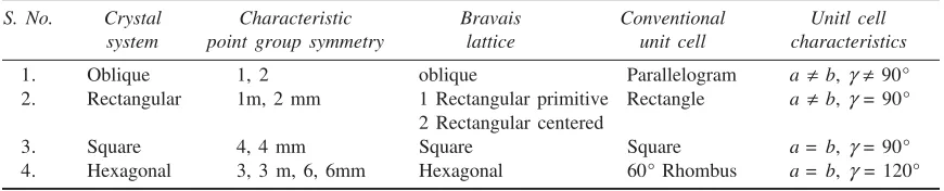
Table 3.1 Crystal systems and Bravais lattices in two dimensions
S. No. Crystal Characteristic Bravais Conventional Unitl cell system point group symmetry lattice unit cell characteristics
1. Oblique 1, 2 oblique Parallelogram a ¹b,g¹ 90°
2. Rectangular 1m, 2 mm 1 Rectangular primitive Rectangle a ¹b,g = 90° 2 Rectangular centered
3. Square 4, 4 mm Square Square a = b, g = 90°
4. Hexagonal 3, 3 m, 6, 6mm Hexagonal 60° Rhombus a = b, g = 120°
Based on pure symmetry considerations, there are only fourteen independent ways of arranging points in three-dimensional space, such that each arrangement is in accordance or in confirmation with the defi-nition of a space lattice. These 14 space lattices with 32 point groups and 230 space groups are called Bravais lattices (Fig. 3.6(b)). If considered as solids, the combination of symmetry elements they exhibit can be determined. Each space lattice can be defined by reference to a unit cell which, when repeated in space an infinite number of times, will generate the entire space lattice. To describe basic crystal structures, the 14 types of unit cells are grouped in seven different classes of crystal lattices, i.e. to describe basic crystal structures, seven different co-ordinate systems of reference axes are required (Fig. 3.7).
A description of the characteristics of 14 Bravais lattices of three dimensions along with the axial relationship for the class of crystal lattices, i.e. seven systems to which each belongs are summarized in Table 3.2.
b t a
(a) (b) (c) (d) (e)
(f) (g) (h) (i)
(j) (k) (l) (m) (n)
Fig. 3.6(b) The 14- Bravais space lattices:
(a) Simple cubic (h) Body-centered orthorhombic
(b) Body centered cubic (i) Face-centered orthorhombic (c) Face-centered cubic (j) Monoclinic
(d) Tetragonal (k) Base-centered monoclinic
(e) Body-centered tetragonal (l) Triclinic
(f) Orthorhombic (m) Trigonal
Fig. 3.7 Seven basic crystal systems with reference axis
Table 3.2 The Bravais lattices in three dimensions (the seven basic crystal systems)
Crystal Lattice No. of Relation Interface Examples system type lattices between angles
primitives
Cubic P, F, C 3 a = b = c a = b = g = 90° Au, NaCl, CaF2, CrCl, CaO (I)} Monoclinic P, B 2 a¹ b¹ c a = b = 90° ¹ g 2H2O, NaSO4, CaSO4, FeSO4} Triclinic P 1 a¹ b¹ c a ¹b ¹g¹ 90° K2Cr2O7, CuSO4, K2S2O8 Tetragonal P, C 2 a = b¹ c a = b = g = 90° NiSO4, Sn, TiO3, and SnO2 Orthogonal P, B, F, C 4 a¹ b¹ c a = b = g = 90° MgSO4, KNO3, and BaSO4 Rhombohedral P or R 1 a = b = c a = b = g¹ 90° SiO2, CaSO4, and CaCO3 (Trigonal)
(orthorhombic)
Hexagonal P 1 a = b¹ c a = b = 90° g = 120° AgCl, SiO2, Zn and Graphite Representation of symbols: P ® primitive, B ® base centred
C® body centered and F® face centered
The number of lattice points in unit cell can be calculated by appreciating the following: Contribution of lattice point at the corner = 18th of the point
Contribution of the lattice point at the face = 12 of the point Contribution of the lattice point at the centre = 1 of the point
Every type of unit cell is characterized by the number of lattice points (not the atoms) in it. For example, the number of lattice points per unit cell for simple cubic (SC), body centered cubic (BCC) and face centered cubic (FCC) lattices are 1, 2 and 4, respectively. We must note that our knowledge about unit cell may not be complete without having a quantitative estimate of its volume. This can be calculated with the help of the relation
5 6 7
1 2 3 4
a
b c
Vc= ®a×[®b ´®c] (1) whereVc stands for the volume of the cell and ®a, ®b and ®c defined so far as the measure of the unit cell edges, are commonly known as lattice parameters.
Now, we shall discuss about the seven type of basic systems mentioned in Table 3.1.
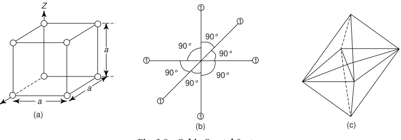
(i) Cubic Crystal System: (a = b = c,a = b = g = 90°): All those crystals which have three equal axes and are at right angles to each other and in which all the atoms are arranged in a regular cube are said to be cubic crystals (Fig. 3.8). The most common examples of this system are cube and octahedron as shown in Fig. 3.8(a) and (c). In a cubic crystal system, we have
a= b = c,a = b = g = 90°
Fig. 3.8 Cubic Crystal System
Atomic Packing Factor (APF): This is defined as the ratio of total volume of atoms in a unit cell to the total volume of the unit cell. This is also called relative density of packing (RDP).
Thus
In a simple cubic cell, no. of atoms in all corners
= 18 ´ 8 = 1 three axes at right angles to each other and two of these axes (say horizontal) are equal, while the third (say vertical) is different (i.e., either longer or shorter than the other two). Figure 3.9(b) shows a tetragonal crystal system. The most common examples of this system of crystals are regular tetragonal and pyramids (Fig. 3.9(a) and (c))
(iii) Hexagonal Crystal System: (a = b¹ c,a = b = g = 90°,g = 120°): All those crystals which have four
(a)
Fig. 3.9 Tetragonal crystal system (b)
Fig. 3.10 Hexagonal crystal system 2
A simple hexagonal unit cell contains one atom at each corner of hexagon and one each at the centre of hexagonal faces. This has hcp structure. There are three atoms at the interstices between two hexagonal faces. The total number of atoms inside the hcp structure is 6 (Fig. 3.11a).
Each corner atom is has 1
6 atom, i.e. shared by 6 other unit lattices.
c
Fig. 3.11 Hexagonal closed packed structure
(a) Three unit cells showing how the hexagonal axis results. One of the cell is fully outlined. (b) Calculation of the ratio c/a. Distance AE is the height of the cell.
Number of atoms in upper hexagonal plane = 1
6 ´ 6 = 1 and number of atoms in lower hexagonal plane = 1
6 ´ 6 = 1.
We can see that each central atom is shared by two unit cells which means upper and lower planes contain 1
2 atom each.
Thus the total number of central atoms in both, upper and lower planes = 1
2 ´ 2 = 1 and we note that there are 3 intersititial atoms.
\ Total number of atoms in hcp crystal
= 1 + 1 + 1 + 3 = 6
APF may be calculated and found to be p 2 6 (= 0.74). This is identical to the packing factor of FCC metal because each has a co-ordination number of 12. The most common examples of such systems are regular hexagonal prisms and hexagonal pyramids as shown in Fig. 3.10(b) and (c). HCP is found in such metals as Ca, Mg, Be, Zn, Cd, Ti and others.
(iv) Orthorhombic Crystal System (a¹ b¹ c,a = b = g = 90°): The space lattice is simple. The crystal axes are perpendicular to one another but all the three axes are essentially of unequal lengths (Fig. 3.12). Orthorhombic lattices may be simple, base centered, body centered or face-centered. Orthorhombic prisms and pyramids (Fig. 3.12(b) and (c)) are most common examples of orthorhombic crystal system.
1 2
3 3
2
1
a c
b
(b)
(c) (a)
Fig. 3.12 Orthorhombic crystal system
(v) Rhom-bohedral or Trigonal Crystal System (a = b = c,a = b = g¹ 90°): Three axes are equal and are
equally inclined to each other at an angle. Other 90° rhombohedral prisms and pyramids (Fig. 3.13(b) and (c)) are the most common examples of this crystal system.
a
a a
(a)
a
a a
(b) (c)
c
a b
Fig. 3.14 Monoclinic crystal system
a c
b
Fig. 3.15 Triclinic crystal system
(vi) Monoclinic Crystal System: (a¹b¹ c,a = b = 90°¹g): Two of the crystal axes are perpendicular
to each other, but the third is obliquely inclined. The repetitive intervals are different along all the three axes. Monoclinic lattices may be simple or base-centered.
(vii) Triclinic Crystal System: (a¹b¹ c,a ¹b¹ g¹ 90°): All those crystals, which have three unequal axes and none of them is at right angles to the other two axes (Fig. 3.15) are included in this crystal system. The repetitive intervals are different along all the three axes. All irregular crystals belong to this class. 10. CRYSTAL STRUCTURE FOR METALLIC ELEMENTS
The most common types of space lattice or unit cells with which most common metals crystallise, are (i) Body-centered cubic structures (BCC)
(ii) Face-centered cubic structures (FCC) (iii) Hexagonal closed-packed structures (HCP)
(i) Body-centered Cubic Structure (BCC): The unit cell of BCC system has an atom at each corner, which are shared by the adjoining eight cubes and one at the body centre (Fig. 3.16). Obviously, each unit cell share 8 atoms one on each of its corners in addition to one atom at the body centre. Hence the share of each cube = 18th of each corner atom.
\ Total no. of atoms = 18 ´ 8 = 1 atom BCC crystal has one atom at the centre = 1 atom
\ Total atoms in BCC unit cell = 1 + 1 = 2 atoms
(Body diagonal)2= Sum of the squares of all the three sides
\ (4r)2= a2 + a2 + a2
or a=
2
16 4
3 3
r r
=
Volume = 2 ´ 4 3 pr
3
= 2 ´
3 3 4
3 4
a
pæçè ö÷ø
\ r= 3
4
a
Volume of unit cell = a3 =
The lattice constant of BCC structure is 9. Some of the metals possessing this structure are a-Fe
(below 910°C), Mo, V, Mn, Nb, W, a – Cr, d-iron (1400°C to 1539°C), etc.
(ii) Face-centered Cubic Structure (FCC): In this type of lattice structure, also known as cubic packed structure, the atoms are located at the eight corners of the cube and at the centre of each face (Fig. 3.17). This type of structure is more common among metals than the BCC structure. It is also formed in ceramic crystals. Cu, Al, Ag, Au, a-Fe, Ca, b-Co, g-Iron (910°C
to 1400°C) are common examples of metals possessing this type of structure. A metal with FCC structure has four times as many atoms as it has unit cells. This means the FCC structure is more densely packed than BCC struc-ture.
Each face atom in FCC structure is shared by two unit cells, or we can say that one face of the FCC unit contains 1/2 atom.
No. of atoms in all six faces = 1
2 ´ 6 = 3 No. of atoms in all corners = 1
8 ´ 8 = 1
\ Total atoms in FCC unit cell = 1 + 3 = 4 atoms From the geometry of FCC structure
We must note that no other structure possesses such a large number of closed-packed planes and directions. This is why, metals with an FCC structure can be deformed critically. The coordination number in an FCC metal is 12 which accounts for the higher atomic packing fraction factor.
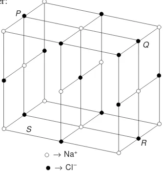
As an example structure of few solids are described hereunder: (i) Sodium Chloride Structure: This is an arrangement in which each positive ion (Na+) is surrounded by six negative ions (Cl–) and vice versa (Fig. 3.18). The ionic radius of Cl– and
Na+ ions is 1.82 Å and 0.98 Å respectively. Obviously, the ratio of Na+ ions is approximately half of Cl– ions. This is why,
for such a high ratio, only 6 Cl– ions be packed around one Na+ ion. Since positive and negative ions must be combined in such a manner so as to keep the net charge zero, i.e. they must be equal in number. This is why they form a cubic structure. The central cube is a FCC unit cell of sodium, while the central plane is the face plane of an overlapping FCC unit cell of chlorine. Obviously, the NaCl structure can, therefore, be viewed as two interpenetrating FCC sublattices, one belonging to Na+ ions with its origin at the point (0, 0, 0) and the other belonging to Cl– ions with its origin at the point (a/2, 0, 0). (ii) Silica Structure: The ratio of silicon to oxygen atoms in Silica is 1 : 2. One silicon atom is surrounded by four oxygen atoms placed at the corners of the tetrahedra. When all the corners one silicon oxygen tetrahedra are shared by the other tetraohedra, the structure is said to be complete. Obviously, every oxygen atom is common to two tetrahedra. The melting point of silica is 1710 °C due to strong primary bonds between silicon and oxygen. The structure of silica is electrically neu-tral, open and having lower density.
R S
® Na+
® Cl–
Fig. 3.18 Sodium chloride structure
Fig. 3.19 Silica structure Oxygen atom
Silicon atom
(iii) Diamond Structure: Diamond exhibits both cubic and hex-agonal type structures. The diamond cubic structure is more common. In diamond structure, each carbon atom is sur-rounded by other four carbon atoms (co-ordination-4). The
limitation on account of number of bonds prevents the formation of closed packed structures. From Fig. 3.20, it is clear that the four nearest carbon atoms (neighbours) are at equal distance from the central atom and they form a tetrahedra. The coordination number of each carbon atom is 4 and the nearest neighbour distance is equal to 3a 4, where a is the lattice parameter. The angles made by the lines joining corner atoms with central atom are 109. 5°. The complete crystal is formed by joining a number of these tetrahedra.
Q P
Z
X
Y
(a) (b)
(iv) Hexagonal Closed Packed (HCP) Structures: In HCP structures, the unit cell contains one atom at each corner of the hexagonal prism, one atom each at the centre of the hexagonal faces and three more atoms within the body of the cell (Fig. 3.21). The HCP structure do not consti-tute a space lattice because the surroundings of the interior atoms and the corner atoms are different. This type of structure is more dense than the simple hexagonal structure. The total number of atoms inside the NCP structure is 6, as shown below.
Each corner atom is shared by six other unit lattices or each corner has 1/6 atom.
Number of atoms in upper hexagonal plane = 1
6 ´ 6 = 1 Number of atoms in lower hexagonal plane
= 1
6 ´ 6 = 1
We note that each central atom is shared by two unit cells which means upper and lower planes contain 1
2 atom each.
\ Total number of central atoms in both, upper and lower planes = 1
2 ´ 2 = 1 and there are three intersititial atoms.
\ Total number of atoms in HCP crystal = 1 + 1 + 1 + 3 = 6 APF =
3 2 ( 4 / 3)
( sin 60 ) r
a a c
p °
where r is the atomic radius. Using c = 1.633a and a = 2r, one obtains,
APF = 2
6
p = 0.74
Obviously, in an ideal HCP structure, 74% of the total volume is occupied by atoms. We further note that the APF value for HCP structure is identical to the APF of an FCC metal because each has a co-ordinate number of 12. The common examples of HCP structure are Be, Mg, Zn, Cd, Ti, Co, Hf, Se, Te, etc. 11. ATOMIC RADIUS
This is defined as half the distance between the nearest neighbours in the crystal structure of a pure element. Atomic radius is denoted by r and expressed in terms of the cube edge element a. One can calculate the atomic radius by assuming that atoms are spheres in contact in a crystal. Calculation of atomic radius in various crystal structures is illustrated as below:
(i) Simple Cubic (SC) Structure: In SC structure, atoms touch each other along the lattice (Fig. 3.22(a)). We have
a= 2r
\ r= a/2
Area a2= 4r2
a (= 2r )
r
r
a
a a
A
C D
a
a 4r
B a
(a) (b)
4r
A
B C
a
a (c)
Fig. 3.22 Atomic radii for three unit cells (a) Simple Cubic (SC) (b) Body-centred cubic (BCC) and (c) Face-centred cubic (FCC)
(ii) BCC Structure: The atoms touch each other along the diagonal of the cube as shown in Fig. 3.22(b). Obviously, the diagonal in this case is 4r. Also,
AC2= AB2 + BC2 = a2 + a2 = 2a2
AD2= AC2 + CD2 = 2a2 + a2 = 3a2
\ (4r)2= 3a2
or a= 4
3
r
and 2r = 3 2
a
\ r= 3
4
a
area a2= 16 2
3 r
(iii) FCC Structure: Atoms within this structure touch along the diagonal of any face of the cube (Fig. 3.22 (c)). The diagonal has a length of 4r.
AC2=AB2 + BC2
or (4r)2= a2 + a2
\ r2= 2 2
16
a
or r= 2
4 2 2
a= a
and area = a2 = 8r2
12. DENSITY OF CRYSTAL This is defined as:
Density of the crystal (r) = Mass of unit cell
Volume of unit cell
Mass of unit cell = Atomic mass
= A
M N ´ n
(n® number of atoms per unit cell and NA® Avogadro’s number, M® the atomic weight, and a® side
of a cubic unit cell).
= 3
A
nM a N
(i) Linear density: This is defined as the number of atoms per unit length along a specific crystal direction. (ii) Planar density: This is defined as the number of atoms per unit area on a crystal plane. This affect significantly the rate of plastic deformation.
13. DIRECTIONS, LATTICE PLANES AND MILLER INDICES
In a crystal there exists directions and lattice planes which contain a large concentration of atoms. Various properties of crystals, particularly mechanical are connected with the structure of the crystal though the help of crystal directions. A complete description of the crystal structure can be obtained from the study of atomic positions in a unit cell. For crystal analysis it is necessary to locate directions and lattice planes. (i) Crystal Directions: To specify the direction of a straight line joining lattice points in a crystal lattice, we choose any lattice point on the line as the origin and express the vector joining this to any other lattice point on the line as follows:
r
Fig. 3.22(d) Crystal directions in a orthorhombic lattice
identical to the direction [111]. As stated earlier, in such cases lowest combination of integers, i.e. [111] is used to specify the direction.
We must note that there are other directions, not parallel to the one under consideration which are equivalent to the given direction by virtue of rotation symmetry. Thus, the equivalent directions of [100] are [010], [001], [100], [010] and [001], where the bars denote the negative values. By all possible positive and negative combinations of indices, we obtain a family of directions. In the present example, all these six equivalent directions are grouped together in the symbol <100>, where the bracket < > represents the whole family.
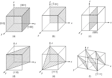
(ii) Crystallographic Planes: The crystal lattice may be regarded as made-up of an aggregate of a set of parallel equidistant planes, passing through the lattice points, which are known as lattice planes, or atomic planes. For a given lattice, one can choose the lattice planes in different ways as shown in Fig. 3.23. These crystal planes and crystal directions play an important role in hardening reaction, plastic deformation and other properties as well as behaviour of metal. Crystal planes in cubic structures are shown in Fig. 3.24.
The direction of the line is represented by the set of integers 1, 2
n n¢ ¢ and n3¢. If these integer numbers have common factors, they are removed and the direction is denoted by [n1,n2,n3]. More-over, this line also denotes all lines parallel to this line. In Fig. 3.22(d), three different directions are shown in the orthorhombic lattice. The direction [111] is the line passing through the origin O and point P. It may be noted that the point P is at a unit cell distance from each axis. The direction [100] is the line passing through origin O and point Q. Obviously, the point Q is at a distance 1, 0, 0 from x,y and z axes respectively. The direction [101] is the line passing through the origin O and the point R. Again, the point R is at a unit cell distance of 1, 0, 1 from x,y and z axes respectively.
z
Fig. 3.24 Crystal planes in cubic structures (a) (010) plane (b) (110) plane and (c) (110) plane and (d) (112) plane
Fig. 3.23 Different crystal planes
The problem is that how to designate these planes in a crystal. Miller evolved a method to designate a set of parallel planes in a crystal by three numbers h, k and l, usually written within brackets thus (h,k, l) known as Miller indices of the plane.
(iii) Determination of Miller Indices:
(a) Determine the coordinates of the intercepts made by the plane along the three crystallographic axes, i.e. x,y,z axes (Fig. 3.25)
x y z
2a 3b c
pa qb rc
(p = 2, q = 3, r = 1)
(b) Now, express the above intercepts as multiples of the unit cell dimensions, or lattice parameters along the axes, i.e.
axes x y z
(c) Take the reciprocal of intercepts 1
(d) Now, reduce these reciprocals to the smallest set of integral numbers and enclose within a bracket 6´ 1
These integers within the bracket are Miller indices. In general it is denoted by (h,k,l). Thus, we note that
Fig. 3.25 Intercepts of plane on three crystallo-graphic axes and Miller indices
1 1 1: :
2 3 1 = 3 : 2 : 6
Obviously,Miller indices are defined as the reciprocals of the intercepts made by the plane on the crystallographic axes when reduced to smallest numbers. We must remember that all planes have same indices. If negative sections are cut off by the plane, this is indicated by a bar above the corresponding index, e.g. 1 (Fig. 3.26).
Figure 3.27 shows the planes in a cubic structure. We can easily see that the Miller indices of the sides of a unit cell of a cubic lattice are (100), (100), (010), (010), (001) and (001). These planes are planes of the same form, i.e. equivalent planes and are collectively represented by {100} and are called families of planes.
Fig. 3.27 Lattice planes in a cubic system. Negative intercepts are indicated on negative coordinates
The lattice or crystallographic direction can be defined as a line joining any two points of the lattice. Using a similar notation, we can describe the direction of a line in a lattice with respect to the unit vectors. We know that Miller indices of a direction are simply the vector components of the direction resolved along each of the co-ordinate axis, expressed as multiples of the unit cell parameters and reduced to their simplest form. They are denoted by [hkl] (to distinguish it from the (hkl) plane).
Just like the principal planes of importance, the directions with which one is mainly concerned are [110], [100] and [111]. We note that these are, respectively, a cube face diagonal, a cube edge and a body diagonal. We can label the families of directions by special brackets as are families of planes. Obviously, <100> denotes the family of directions which includes [100], [010], [001], [100], [010] and [001]. Figure 3.27 (g) and (h) shows the Miller indices for directions: (i) cubic lattice system and (ii) Hexagonal lattice system.
c
[101]
a [110]
[101]
[111]
b
(g) Cubic lattice system
d
a b
(h) Hexagonal system
Fig. 3.27 Miller indices for directions
(iv) Important Features of Miller Indices of Crystal Planes: A few important features of Miller indices of crystal planes are:
(a) All the parallel equidistant planes have the same Miller indices. Obviously, Miller indices define a set of parallel planes.
(b) A plane parallel to one of the coordinate axis has an intercept of infinity (¥) and therefore the Miller index is zero.
(c) If the Miller indices of the two planes have the same ratio (i.e., say 844 and 422 or 211), then the planes are said to be parallel to each other. In other words, all equally spaced parallel planes with a particular orientation have the same index number [hkl].
(d) Only the ratio of indices is important.
(e) Miller indices of planes are denoted by (hkl), i.e., the plane cuts the axes into h, k and l equal segments. The directions in space are represented by square bracket [xyz].
(f) The common inside brackets are used separately and not combined. Obviously, (111) is read as one-one-one and not ‘one hundred eleven’.
(g) Miller indices may also be negative and negative indices are represented by putting a bar over the digit, e.g. (010).
14. INTERPLANAR SPACINGS
These are the distances between planes and are represented by a number of parts of the body diagonal of a unit cell. In terms of Miller indices, the distance between planes can be calculated. Let us consider a plane
c
120°
with Miller indices (hkl). This has intercepts a/h, b/k and c/l on the three axes x,y and z respectively as shown in Fig. 3.28(a). If d is the length of the normal from the origin, O to the plane and a¢, b¢ and g¢ are angles which the normal makes with the coordinates
axes, considered orthogonal, then we have d= a
h cos a¢ = b
k cos b¢ = c l cos g¢
Since cos2 a¢ + cos2b¢ + cos2 g¢ = 1, we have Fig 3.28(a) Calculation of interplanar spacings
z
x A B y
C
O g¢
dhkl=
dhkl gives the distance between two successive (hkl) places. For a cubic system: a = b = c
\ dhkl=
2 2 2
a
h +k +l (5)
For a cubic system lattice, the direction [hkl] is perpendicular to the plane (hkl).
There are three d111 interplanar spacings per long diagonal (body diagonal) of a unit cell in an FCC structure. We must note that relation (4) is valid for orthogonal lattices only. For non-orthogonal lattices, such an expression may not be obtained easily.
14(a). ANGLE BETWEEN TWO PLANES OR DIRECTIONS
Let us consider a cube having two planes ABCD and EFCD inclined at an angle q with each other (Fig. 3.28(b)). Let h1,k1,l1 are Miller indices of plane ABCD and h2,k2 and l2 are Miller indices of plane EFCD.
The angle between these two planes is given by the relation
cos q= 1 2 1 2 1 2
Similarly, the angle f between the two directions having
Miller indices (h1,k1,l1) and (h2,k2,l2) respectively is given
(100), (010) and (001) represent the Miller indices of the cubic planes ABCD, BFGC and AEFB respectively (Fig. 3.29).
Fig. 3.29 Crystal planes of a cubic unit cell
Obviously, the above mentioned three planes represent the three faces of the cubic unit cell. We can represent the other three faces of the cube by shifting the origin of the coordinate system to another corner of the unit cell, e.g. the plane EFGH may be represented by shifting the origin from point H to point D
G
z
Fig. 3.30 Crystal planes obtained after shifting the origin
(Fig. 3.30(a)). We note that now the values of the intercepts are—1 along x-x axes, ¥ along y-y and z-z axes. Thus the Miller indices are (100). Similarly, we obtain Miller indices for the planes AEHD and DHGC as (010) and (001) respectively by shifting the origin to the points G and E (Fig. 3.30(b) and (c)). All the six faces of the cubic unit cell have same geometry, i.e. they are of the same form. Thus Miller indices of all the six planes are represented by {100}. This represents a set of six planes (100), (010), (011), (100), (010) and (001). Similarly {110} represents a set of six planes (110), (101), (011), (110), (101), and (011) (Fig. 3.31). (a) Plane (110) (b) Plane (101)
D C
Fig. 3.31 Crystal planes corresponding to {110}
We must note that these planes represent diagonal planes, where each diagonal plane is formed by joining two opposite edges of the unit cell. There are 12 edges of a cubic unit cell and hence there are 6 diagonal faces represented by {110} (Fig. 3.31).
Similarly, {111} represents a set of four planes (111), (1 11), (111) and (11 1), which are four trian-gular planes of the unit cubic cell (Fig. 3.32).
z
Fig. 3.32 Crystal planes corresponding to {111}
16. SKETCHING THE PLANE FROM THE GIVEN MILLER INDICES From a given Miller indices, one can sketch the planes. The procedure is as follows:
(i) First, take the reciprocal of the given Miller indices. These reciprocals represent the intercepts in terms of the axial units along x-x, y-y and z-z axes respectively. For example, if the given Miller indices are (211), then its reciprocals or intercepts will be 1/2, 1/1 and 1/1 or 0.5, 1, 1 respectively.
(ii) Now, we should sketch the plane with intercepts. Here with 0.5, 1, 1 along x-x,y-y and z-z axes respectively (Fig. 3.33).
17. COMMON PLANES IN A SIMPLE CUBIC STRUCTURE
One can draw a number of planes in a simple cubic structure, but the most common planes are (100), (110) and (111). One can draw these common planes as follows:
(i) Plane of (100): In this case: h = 1, k = 0 and l = 0. The reciprocals of h, k and l are 1/1, 1/0 and 1/0 = 1, ¥,¥. On sketching the plane with intercepts 1, ¥,¥ along x-x,y-y and z-z axis respectively, we obtain the plane as shown in Fig. 3.34(a).
Fig. 3.33 Plane (211)
Fig. 3.34 Common planes in a simple cubic structure
E F
(ii) Plane of (110): Here h = 1, k = 1 and l = 0. The reciprocals of h,k,l are 1/1, 1/1 and 1/0 = 1, 1, ¥. Now, sketching the plane with intercepts 1, 1 ¥, one obtains the plane as shown in Fig. 3.34(b). (iii) Plane of (111): We have h = 1, k = 1 and l = 1. The reciprocals of h, k, l are 1/1, 1/1, 1/1 i.e. 1, 1, 1. Sketching the plane with intercepts 1, 1, 1, one obtains the plane as shown in Fig. 3.34(c).
18. CO-ORDINATION NUMBER
This is defined as the number of nearest atoms directly surrounding the given atom. The value of co-ordination number is 6 for simple cubic, 8 for BCC and 12 for FCC (Fig. 3.34d). In closely packed structures this number is 12. The coordination number of carbon is 4, i.e. number of nearest neighbours of carbon atom is 4. This low coordination, results in a relatively inefficient packing of the carbon atoms in the crystal.
P l F F
Fig. 3.34(d) The coordination number in three cubic lattices
Example 1 Determine the relationship between the lattice parameter a and the atomic radius r for
monoatomic, SC, BCC and FCC structures
Solution In simple cubic (SC) structure, the atoms touch one another along the cube edges,
\ a= 2r
In BCC, the atoms touch along the body diagonals,
\ 3a= 4r
a SC
a BCC
a FCC
a (100)
3a
(110) (111)
2a
Fig. 3.35 Monoatomic, SC, BCC and FCC structures along with their (100), (110) and (111) type planes respectively
or a= 4
3 r
In FCC structure, the atoms touch along the face diagonals,
\ 2a= 4r
or a= 2 2r.
Example 2 An atomic plane in a crystal lattice makes intercept of 3a, 4b and 6c with the crystallographic
axes where a, b and c are the dimensions of the unit cell. Show that the Miller indices of the atomic plane are (432).
Solution In terms of the lattice constants, the intercepts are 3, 4 and 6. Their reciprocals are 1/3, 1/4,
1/6. On reducing to a common denominator, they become 4/12, 3/12 and 2/12. Obviously, the Miller indices of the plane are (432).
Example 3 In a single cubic crystal find the ratio of the intercepts on the three axes by (123) plane. Solution The reciprocals of Miller indices are 1/1, 1/2 and 1/3. On reducing to a common denominator
they become 6, 3 and 2. Intercepts on the three axes are 6a, 3b and 2c, where a, b and c are the lattice constants along the three axes.
Example 4 Draw (101) and (111) planes in a unit cubic cell. Find the Miller indices of the directions
which are common to both the planes.
Solution Intercepts of the plane (101) with the three axes are 1/1,
1/0 and 1/1 i.e. 1, ¥ and 1. Similarly, the intercepts of the (111) with the three axes are 1/1, 1/1 and 1/1, i.e. 1, 1 and 1.
Now, taking the point O as origin and lines OA,OB and OC as the axesa, b and c respectively, the plane with the intercepts 1, ¥ and 1 is the plane ADGC and that with intercepts 1, 1 and 1 is plane ABC (Fig. 3.36). From figure, it is obvious that the line common to both the planes is the line AC. This line corresponds to two directions, i.e., AC and CA.
Projections of the direction AC on the axes are –1, 0 and 1. Pro-jections of direction CA on the axes are 1, 0 and –1.
Thus the required indices are [101] and [101].
Example 5 Draw the following planes and directions in the case of a FCC structure: (112), (001) and
(101).
Fig. 3.36 Planes (101) and (111) in a simple cubic lattice
E
(a) Plane (112) (b) Plane (001)
(ii) Plane of (001): Here h = 0, k = 0, l = 1. The reciprocals are 1/0, 1/0, 1/1 i.e., ¥,¥, 1. We obtain the sketch of the plane as shown in Fig. 3.37(b).
(iii) Plane of (101): Here h = 1, k = 0 and l = 1. The reciprocals are 1/1, 1/0 and 1/1, i.e. 1, ¥ and 1. We obtain the sketch as shown in Fig. 3.37(c).
Example 6 A plane makes intercepts of 1, 2 and 0.5 Å on the
crystallographic axes of an orthorhombic crystal with a : b : c = 3 : 2 : 1. Find the Miller indices of this plane.
Solution Taking the lengths of the axes OA, OB and OC as 3, 2 and
1Å respectively, we obtain the plane with intercepts of 1, 2 and 0.5 Å on the axes is the plane DBE (Fig. 3.38). The intercepts of this plane relative to full lengths of the axes are: 1/3, 2/2 and 0.5/1 or 1/3, 1 and 1/2. Reciprocals are: 3, 1 and 2. Obviously, the Miller indices of the plane DBE are (312).
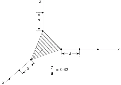
Example 7 Sketch (111) plane of a unit cell of simple tetragonal
crystal. Given c/a = 0.62.
Solution Fig. 3.39 shows the plane (111). The plane cuts the three axes at unit distances. We note that
the unit distance along z-axis is shorter than the unit distance of other two axes.
Fig. 3.38 (312) plane in an orthorhombic lattice C
E
O
®
b B
D ®a
®
c
A
x
c
c a = 0.62
y a
a
Fig. 3.39 The plane (111) z-axis shorter
Example 8 Draw the planes (020), (120) and (220) in a FCC structure.
Solution (i) Plane of (020): Given h = 0, k = 2 and l = 0. The reciprocals are 1/0, 1/2, 1/0, i.e. ¥,
0.5, ¥.
Sketching the plane with intercepts ¥, 0.5, ¥ along x-x,y-y and z-z axes respectively, we obtain the plane (020) (Fig. 3.40(a)).
(ii) Plane of (120): Here h = 1, k = 2, and l = 0. The reciprocals of h, k, l are 1/1, 1/2, 1/0, i.e. 1, 0.5, ¥.
Sketching the plane, we obtain as shown in Fig. 3.40(b).
(iii) Plane of (220): Here h = 2, k = 2, and l = 0. The reciprocals of h,k,l are 1/2, 1/2, 1/0, i.e. 0.5, 0.5,
¥. The plane obtained is as shown in Fig. 3.40(c).
z
x
y
(a) Plane (020)
z
x
y
(b) Plane (120)
z
x
y
(c) Plane (220)
Fig. 3.40
Example 9 Draw the planes and directions of FCC structures (321), (102), (201) and (111).
[B.E. 2001]
Solution (i) Plane and Direction of (321): Here h = 3, k = 2, and l = 1. The reciprocals are 1/3, 1/2,
1/1, i.e. 0.3, 0.5, 1. The sketch of the plane with intercepts 0.3, 0.5 and 1 is as shown in Fig. 3.41(a). A line drawn normal to this sketched plane and passing through the origin gives the required direction.
z
(321)
x
1/3
y 1/2
[3, 2, 1]
(a)
z
[102]
x
y (102)
(b)
z
[201]
x
y (201)
z
[111]
x
y (111)
(c) (d)
Fig. 3.41
(ii) Plane and Direction of (102): Here h = 1, k = 0, and l = 2. The reciprocals of these are: 1/1, 1/0 and 1/2, i.e. 1, ¥, 0.5. The sketch of the plane with these intercepts is as shown in Fig. 3.41(b). A line drawn normal to this sketched plane and passing through the origin gives the required direction.
(iii) Plane and Direction of (011): Here h = 0, k = 1, and l = 1. The reciprocals of h and k, l are: 1/0, 1/1, 1/1, i.e. ¥, 1.1. The sketch of the plane with these intercepts is shown in Fig. 3.41(c). A line drawn normal to this sketched plane and passing through the origin gives the required direction.
Example 10 In a cubic unit cell, find the angle between normals to the planes (111) and (121). Solution Since the given crystal is cubic, the normals to the planes (111) and (121) are the directions
[111] and [121] respectively. If q be the angle between the normals, then
cos q=
Example11 Determine the packing efficiency and density of sodium chloride from the following data:
(i) radius of the sodium ion = 0.98 Å, (ii) radius of chlorine ion = 1.81 Å (iii) atomic mass of sodium = 22.99 amu and atomic mass of chlorine = 35.45 amu.
Solution The unit cell structure of NaCl is shown in Fig. 3.18. We can see that the Na+ and Cl– ions touch
along the cube edges.
\ Lattice parameter, a= 2 (radius of Na+ + radius of Cl–) = 2(0.98 + 1.81) = 5.58 Å
Atomic Packing Fraction = Volume of ions present in the unit cell Volume of the unit cell
=
Density = Mass of the unit cell Volume of the unit cell
=
Example 12 Aluminium has FCC structure. Its density is 2700 kg/m3. Find the unit cell dimensions and
atomic diameter. Given at. weight of Al = 26.98. [Roorkee]
For FCP structure, r= 4.048 Å 2 1.414 2 1.414
a =
´ ´ = 1.43 Å
\ Diameter = 2r = 2.86 Å
Example 13 Find the interplanar distance of (200) plane and (111) plane of Nickel crystal. The radius
of Nickel atom is 1.245 Å. [Jodhpur]
Solution Nickel has FCC structure. Given radius of Nickel = r = 1.245 Å
Lattice constant = a = 4 4 1.245
Example 14 The lattice constant of a unit cell of KCl
crys-tal is 3.03 Å. Find the number of atoms/ mm2 of planes (100), (110) and (111). KCl has simple cubic structure.
[B.E]
Solution a= 3.03 Å = 3.03 ´ 10–7mm.
(100) plane The number of atoms in the (100) plane of a
C (111) (110) E1
F G
O B
A D
[110]
Fig. 3.42 Plane in a unit cell of FCC Nickel
(110) plane The number of atoms in (110) plane of a simple cubic structure =
(111) plane The number of atoms in (111) plane of a simple cubic structure =
Example 15 Determine the planar density of Ni (FCC
structure) in (100) plane. Given, the radius of Ni atom = 1.245 Å.
Solution From Fig. 3.43, we have
Number of atoms in (100) plane = 1 + 1
= 3.52 Å Fig. 3.43 Interplanar distances in Ni crystal
4r
\ Planar density =
7 2
2
( 3.52 10´ - mm ) = 16.1 ´ 10
12 atoms/mm2
Example 16 Calculate the planar atomic densities of planes (100), (110) and (111) in FCC unit cell and
apply your result for lead (FCC form). [AMIE]
Solution (i)Plane (100): Fig. 3.44(a) shows an FCC unit cell with planes (111) and (111). Figure 3.44(b)
shows the plane (100) with atoms on it. Similarly Figs. 3.44(c) and (d) shows the planes (110) and (111) with atoms contained in them respectively.
b
(111)
a
c
(a)
(110)
(110)
(b) (c)
2a
(d) 2a
Fig. 3.44 Distribution of atoms in planes (100), (110) and (111) in FCC unit cell
Number of atoms contained in (100) plane is 4 ´ 1
4 + 1 = 2 Let a be the edge of the unit cell and r the radius of the atom, then
a= 2 2 r \ Planar density of plane (100)
=
2 2
0.25 2
4 2´ r = r
The radius of lead atom is 1.75 Å. The planar density of (100) plane of lead
=
7 2 0.25
(1.75 10 )´ - = 8.2 ´ 10
12 atoms/mm2
= 8.2 ´ 1018 atoms/m2
(ii) Plane (110): From Fig. 3.44(c), we have the number of atoms contained in plane (110) = 4 ´ 1
The top edge of the plane (110) is 4r, whereas the vertical edge = a = 2 2 r. Thus the planar density of (110)
=
2 2 8 2r
= 0.177/r2
In case of (110) plane in lead, we have planar density =
2 2 0.177 (1.75 10 )´
-(iii) From Fig. 3.44(d), we have the number of atoms contained in the plane (111) = 3 ´ 1 3
6+ 2 = 2 Area of (111) plane = 1 3 2 4 3 2
2 2 a a= r
\ Planar density of (111) =
2 2
0.29 2
4 3r = r
For lead crystal, we obtain the value 9.5 ´ 1012 atoms/mm2.
Example 17 Determine the linear atomic density in the [110] and [111] directions of copper crystal
lattice. Lattice constant of copper (FCC) is 3.61 ´ 10–10 m. [AMIE]
Solution From Fig. 3.45 and earlier discussions. We note that the face
di-agonal along [110] direction intersects two half diameters and one full diam-eters. Thus the number of diameters of atom along [110] direction
= 1
2 + 1 + 1 2 = 2
Let a be the lattice constant, then the length of the face diagonal = 2 a \ Linear density of [110] within unit cell
= 2 2
2a= a
Since a= 3.61 ´ 10–10 m = 3.61 ´ 10–7 mm
\ r110= 2 7
3.61 10´ - = 3.92 ´ 10
6 atoms/mm
The direction [111] is along the body diagonal. From Fig. 3.45, the length of the diagonal along [111]
=
2a2+a2 = 3aThe number of atomic diameters intersected by diagonal along [111] is 1 2 +
1
2 at two ends. Thus the linear density along [111] within the crystal unit cell
= 1
3a = 7
1
3 3.61 10´ ´ - = 1.6 ´ 10
6 atoms/mm
Obviously, in FCC the linear density along [110] direction is greater than that along [111] direction. Fig. 3.45
[111]
Example 18 The density of a– Fe is 7.87 ´ 103 kg/m3. Atomic weight of Fe is 55.8. If a– Fe crystallizes
in BCC space lattice, find lattice constant. Given Avogadro’s number (N) = 6.02 ´ 1026/kg/mole.
[AMIE]
Solution Lattice constant (a) can be obtained from the relation,
a3=
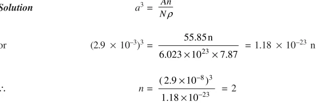
Example 19 Show that the number of atoms per unit cell of a metal having a lattice parameter of
2.9 Å and density of 7.87 gm/cc is 2. Given atomic weight of metal = 55.85 and N = 6.023 ´ 1023
19. DEFECTS OR IMPERFECTIONS IN CRYSTALS
Up to now, we have described perfectly regular crystal structures, called ideal crystals and obtained by combining a basis with an infinite space lattice. In ideal crystals atoms were arranged in a regular way. However, the structure of real crystals differs from that of ideal ones. Real crystals always have certain defects or imperfections, and therefore, the arrangement of atoms in the volume of a crystal is far from being perfectly regular.
Natural crystals always contain defects, often in abundance, due to the uncontrolled conditions under which they were formed. The presence of defects which affect the colour can make these crystals valuable as gems, as in ruby (chromium replacing a small fraction of the aluminium in aluminium oxide : Al2O3). Crystal prepared in laboratory will also always contain defects, although considerable control may be exercised over their type, concentration, and distribution.
The importance of defects depends upon the material, type of defect, and properties which are being considered. Some properties, such as density and elastic constants, are proportional to the concentration of defects, and so a small defect concentration will have a very small effect on these. Other properties, e.g. the colour of an insulating crystal or the conductivity of a semiconductor crystal, may be much more sensitive to the presence of small number of defects. Indeed, while the term defect carries with it the connotation of undesirable qualities, defects are responsible for many of the important properties of mate-rials and much of material science involves the study and engineering of defects so that solids will have desired properties. A defect free, i.e. ideal silicon crystal would be of little use in modern electronics; the use of silicon in electronic devices is dependent upon small concentrations of chemical impurities such as phosphorus and arsenic which give it desired properties. Some simple defects in a lattice are shown in Fig. 3.46.
b a
d e
c
key:
a = vacancy (Schottky defect) b = interstitial
c = vacancy—interstitial pair (Frenkel defect) d = divacancy
e = split interstitial = vacant site
Fig. 3.46 Some simple defects in a lattice
hysteresis, dielectric strength, condition in semiconductors, which are termed structure sensitive are greatly affected by the relatively minor changes in crystal structure caused by defects or imperfections. Crystalline defects can be classified on the basis of their geometry as follows:
(i) Point imperfections (ii) Line imperfections
(iii) Surface and grain boundary imperfections (iv) Volume imperfections
The dimensions of a point defect are close to those of an interatomic space. With linear defects, their length is several orders of magnitude greater than the width. Surface defects have a small depth, while their width and length may be several orders larger. Volume defects (pores and cracks) may have substantial dimensions in all measurements, i.e. at least a few tens of Å. We will discuss only the first three crystalline imperfections.
20. POINT IMPERFECTIONS
The point imperfections, which are lattice errors at isolated lattice points, take place due to imperfect packing of atoms during crystallisation. The point imperfections also take place due to vibrations of atoms at high temperatures. Point imperfections are completely local in effect, e.g. a vacant lattice site. Point defects are always present in crystals and their present results in a decrease in the free energy. One can compute the number of defects at equilibrium concentration at a certain temperature as,
n=N exp Ed
kT
-é ù ê ú
ë û (8)
Where n® number of imperfections, N ® number of atomic sites per mole, k® Boltzmann constant, Ed® free energy required to form the defect and T® absolute temperature. E is typically of order l eV; since k = 8.62 ´ 10–5 eV/K, at T = 1000 K, n/N = exp[–1/(8.62 ´ 10–5 ´ 1000)]
; 10–5, or 10 parts per
million. For many purposes, this fraction would be intolerably large, although this number may be reduced by slowly cooling the sample.
(a) Vacancy defect (b) Interstitial defect
(c) Frenkel defect (d) Substitutional defect
(e) Schottky defect
Fig. 3.47 Point defects in a crystal lattice
corresponding equilibrium concentration of vacancies and interstitial atoms (an interstitial atom is an atom transferred from a site into an interstitial position). For instance, copper can contain 10–13 atomic percentage of vacancies at a temperature of 20–25°C and as many as 0.01% at near the melting point (one vacancy per 104 atoms). For most crystals the said thermal energy is of the order of l eV per vacancy. The thermal vibrations of atoms increases with the rise in temperature. The vacancies may be single or two or more of them may condense into a di-vacancy or trivacancy. We must note that the atoms surrounding a vacancy tend to be closer together, thereby distorting the lattice planes. At thermal equilibrium, vacancies exist in a certain proportion in a crystal and thereby leading to an increase in randomness of the structure. At higher temperatures, vacancies have a higher concentration and can move from one site to another more frequently. Vacancies are the most important kind of point defects; they accelerate all processes associated with displacements of atoms: diffusion, powder sintering, etc.