Compliance with these operating instructions is considered part of the intended use of the controller/actuator. Only a standard supply current of approx. is required to supply the galvanically isolated network part of the AUMATIC DeviceNet interface. The physical DeviceNet interface of the devices is designed for exchanging the devices during active DeviceNet communication.
External electronics supply (option) .. Options: Reverse contactors1) (mechanically and electrically interconnected) for motor power up to 7.5 kW. OPEN – STOP – CLOSE – RESET local controls can be disabled or released via DeviceNet. Motor protection rating Standard: Motor temperature monitoring in combination with thermo switches on the actuator motor.
Intermediate positions Every 8 intermediate positions between 0 and 100 % Response and signal behavior programmable DeviceNet interface settings/programming. Automatic noise rate detection or baud rate setting via Clear Messages or via local AUMATIC controls as an alternative.

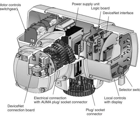
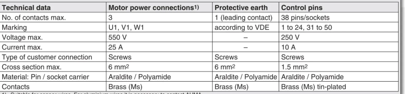
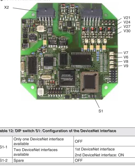
AUMATIC DeviceNet design
Electrical connection Work on the electrical system or equipment must only be carried out by a skilled electrician himself or by specially
- Power supply (standard) For explosion-proof version (type designation: ACExC) see page 17
- Remote position transmitter For the connection of remote position transmitters (potentiometer, RWG) screened cables must be used
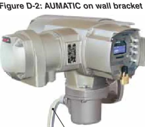
- AUMATIC on wall bracket The AUMATIC can also be mounted separately from the actuator on a wall bracket
- Fitting of the connection housing
- Check limit and torque switching
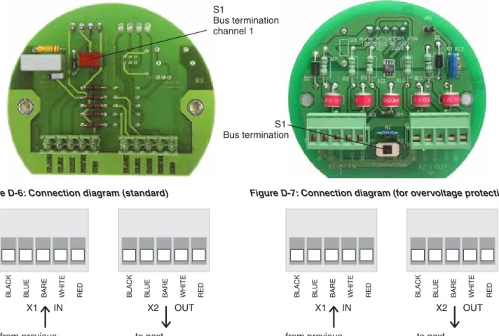
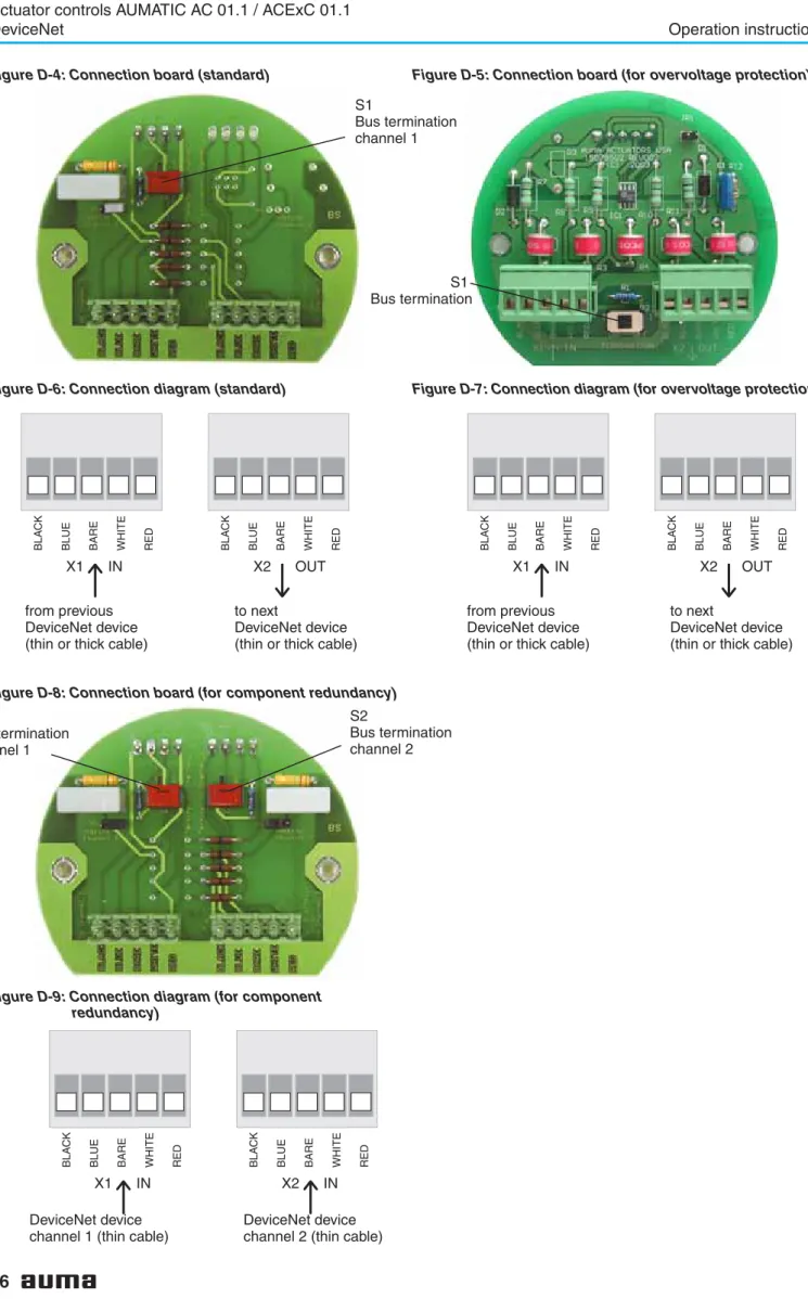
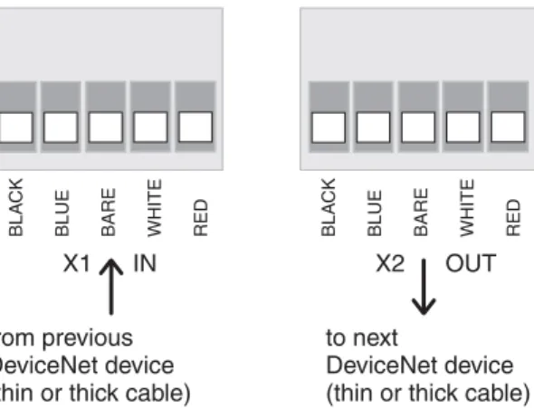
- Bus connection (standard) For explosion-proof version (type designation: ACExC) see page 17
- Mains and bus connection for explosion-proof version
- Setting the DeviceNet address and the baud rate via the local controls
- Further parameters of the DeviceNet interface
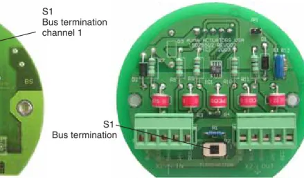
The terminating resistor may only be switched on if the actuator is the last master station in the DeviceNet main line. This must be taken into account when planning the DeviceNet topology (location Figure D-3: AUMATIC bus. For the Ex plug-in connector (Figure D-10), the electrical connection is made after removing the plug cover. (50.0) on the terminals of the EEx e terminal board (51.0) .
It must be ensured that there are no potential differences between the individual participants on the DeviceNet (carry out potential compensation). For further information on the display, operation and setting of the AUMATIC, please refer to the operating instructions of the actuator (multiturn actuator SA(R) ... / swivel actuator SG .... with AUMATIC AC. Alternatively, you can also disconnect the DeviceNet power supply for a short period of time. detach.
Use address 64 to enable MAC ID setting via DeviceNet (in this case the DeviceNet address can be determined via Clear Messages of the process control system, eg with RSNetWorx from Allen-Bradley). You can use these parameters to configure the DeviceNet data interface (see also page 49 ff).

MAIN MENU (M) SETTINGS (M1)
To return to the previous display without accepting the entered value, press the push button. After the actuator address has been changed, the AUMATIC must be switched off for a short time.
SELECTED CONS.PATH (M1MX5) SELECTED PROD.PATH (M1MX6)
SELECTED CONS.PATH : PROCESS OUTPUT SELECTED PROD.PATH : PROCESS INPUT
BUS-OFF INTERRUPT (M1MX7) Standard value
HEARTBEAT INTERVAL: 0S
- Commissioning with controls
- Functions of the AUMATIC with DeviceNet
- Object model of the AUMATIC Figure G: Object model of the AUMATIC
- Bus access
- Poll I/O data interface of the AUMATIC
- Description of the input data
- AN.INPUT 3 EXTENDED 2 AN.INPUT 4
- extended)
- Logical sig-
- Actuator
- E2 (Feed-
- Options
- Analogue in-
- Logical
- E2 Feed-
- Fault
- Warning
- Warnings
- options)
- Fault sig-
- Analogue
- Additional
- Detailed description of the input data
- Description of the output data
- E1 set-
- Detailed description of the output data
- Additional
- Operation parameters of the actuator
- Description of actuator functions
- Release function of the local controls (option)
The AUMATIC is pre-configured at the factory with one of the instances described in Chapter 9 (according to the ordering data). A commercially available configuration tool (e.g. RSNetWorx from Allen-Bradley) can be used to configure the data interface. The value sent is the current torque in per mille of the nominal torque of the drive.
I/O1 Analog In1 loss Loss of signal from the analog input 1 of the parallel interface (only for DeviceNet in combination with parallel interface). I/O1 Analog In2 loss Loss of signal from the analog input 2 of the parallel interface (only for DeviceNet in combination with parallel interface). Internal error The internal diagnostics of the AUMATIC detected an error (the exact cause can be seen on diagnostics page D2 and DQ of the screen).
Internal warning The internal diagnosis of the AUMATIC has detected a warning (the exact cause can be found via diagnosis page D3 of the display). This signal allows certain indications of the AUMATIC to be reset (e.g. PTC trip device and pairing errors). The function of this bit is the same as the Reset push button of the local control in selector switch position LOCAL.
Parameter access to the DeviceNet network data (the meaning of the parameters is described in detail in the operating instructions of the actuator “Multi-turn actuators SA ../single-turn actuators SG .. with AUMATIC AC”). DeviceNet-specific parameters (the meaning of the parameters is described in detail in the operating instructions of the actuator “Multi-turn actuators SA ../single-turn actuators SG .. with AUMATIC AC”). Parameters for setting the application functions of the AUMATIC (the meaning of the parameters is described in detail in the operating instructions of the drive “Multiturn drives SA ../swing drives SG .. with AUMATIC AC”).
Access to AUMATIC AC 01.1 parameters via Explicit DeviceNet Messages is usually gained using the EDS (Electronic Data Sheet) file in combination with a configuration tool, e.g. The operation commands are determined by the operation command bits and the nominal value (setting) of the data output. Via the 'NOMINAL' position (setpoint) at the data output, the nominal value of the position is transmitted to the actuator as a nominal variable.
Link timing is defined by the value of the Expected Packet Rate (EPR) attribute of the link objects (Class ID = 5, Instance ID = 2, Attribute ID = 9). If a Poll link failure has been detected with this function, the drive will stop even if the safety function is not activated.

CONFIGURATION (M4) SETUP (M41)
The AUMATIC can be set so that the AUMATIC internal selector switch position is additionally determined by 3 bits in the process display output. This makes it possible to enable (enable) or disable a particular selector switch position from REMOTE via DeviceNet.
SELECTOR SWITCH (M410V) ENABLE LOCAL MODE (M410W)
AVAILABLE )
NOT AVAILABLE )
Additional control inputs (option)
The digital and analog input signals of the DeviceNet interface can be interpreted as additional control commands. This makes an additional control command channel available (four digital inputs or one analogue 0/4 – 20 mA input). Regardless of the signal assignment of these inputs, fieldbus communication with the DCS remains intact.
EXTERNAL INPUTS BUS (M410G)
Combination fieldbus / standard interface (option)
This makes an additional control command channel (digital inputs or an analog 0/4 – 20 mA input) available and the available feedback options of the I/O interface (relay contacts, analog feedback) can also be used to control the feedback signals sent via the fieldbus. . Regardless of the signal assignment of these inputs, fieldbus communication with the DCS remains intact. The settings for the I/O interface and the fieldbus interface are made via the following menus:.
EMERGENCY STOP function (option)
As an option, the AUMATIC can also be equipped with an EMERGENCY STOP push button. Limitations The EMERGENCY STOP function is not available for ACExC, but only for the weatherproof versions of the AUMATIC. Function Once this EMERGENCY STOP button is activated, several steps are carried out in the AUMATIC.
Indication of EMERGENCY STOP status by setting a bit in the process representation output (byte 9 – Not ready in., bit 4 – Emcy STOP active). Optional: Indication of the operating status of the EMERGENCY STOP button when activating a signal relay. Optional: Indication of the operating status of the EMERGENCY STOP button by lighting up a local control LED.
Display of the EMERGENCY STOP status on the display with the entry “EMCY STOP ACTIVE” on the diagnosis page S3 “NOT READY IND.”. EMERGENCY STOP status display in the status display S0: Opera feedback signals on the DeviceNet display Note. After unlocking the EMERGENCY STOP button, any active operating command is not immediately reactivated, but only after confirmation from the user has been given, which resets the EMERGENCY STOP status.
To confirm, press the RESET button on the local controls in the LOCAL switch position to reset the controls to normal operation. As an alternative to the confirmation with the RESET button, it can also be done with the RESET bit on the process representation output (when the selector switch is in position REMOTE).
OUTPUT RELAY X
LOCAL CONTROLS (M14) LED X LOCAL CONTROLS
LOCAL CONTROLS = EMCY STOP BUTTON
Redundant bus connection with component redundancy (option)
- Settings for the redundant DeviceNet interface 2 (component redundancy)
In this version, communication with the actuator can be established simultaneously through both DeviceNet interfaces. If there is communication with the master available via both DeviceNet interfaces, the operation commands of the interface that originally established communication with the master will be executed. The redundant DeviceNet component 2 is set in the same way as the setting for DeviceNet component 1 (see page 20 ff) and so on.
SETTINGS (M1)
BAUDRATE SW.VALUE (M1NX0) MAC ID SW.VALUE (M1NX2)
- External change-over of the communication channels
- Channel 2
- Designation
- Indication and programming of the AUMATIC
- BUS-OFF
- Description via DeviceNet interface
- Trouble shooting and corrective actions
- Appendix A EDS file The EDS file can be downloaded from the Internet
- Appendix B standard wiring diagram Legend page 61
- Appendix C Proposed wiring diagrams
- Appendix D Literature references
- Appendix E Connection of the screen for AUMATIC ACExC 01.1
If the channel change bit is set, adding the second bit has no effect. Each change of value of one parameter of the DeviceNet interface increases the value of the parameter by 1, i.e. LED 'DATA EX' (V6) (green) When LED is lit, the DeviceNet interface 'Data Exchange'- state entered (see page 55).
Only in this mode can the actuator be controlled by the DeviceNet master and the status of the actuator can be read. For detailed notes regarding indication and operation see the relevant operating instructions for the actuator. The Offline Connection Kit can be used to reconnect a DeviceNet node after a COMMUNICATION FAILURE (due to a duplicate MAC ID or a bus-off status) to the DeviceNet network.
Using the Reset service (Service code 05hex) of the Identify Object (Class ID 01hex), the AUMATIC can be reset to the default settings (out of the box defaults) (Reset Type = 1). DV DN1 MODULE STATUS Module status of the DeviceNet interface 1 NOT POWERED No DeviceNet power supply available. DW DN1 CURRENT VALUES Current values for the baud rate and MAC ID for DeviceNet interface 1 DX DN2 HRDWR. VER.1) Hardware version of the DeviceNet interface 2.
DY DN2 SFTWR.VER.1) DeviceNet 2 interface software version DZ DN2 BUS STATUS1) DeviceNet 2 interface status; .. the content is the same as the content of DeviceNet interface 1 Yes DN1 NET STATUS1) Network status of DeviceNet interface 2; .. the content is the same as the content of the DeviceNet interface 1 Db MODULE STATUS DN21) Status of the DeviceNet interface module 2; .. content identical to DeviceNet interface 1. Dc DN2 CURRENT VALUE1) Current values of baud rate and MAC ID of DeviceNet interface 2. DeviceNet interface of DeviceNet component defective DeviceNet field wiring/ defective DeviceNet master defective / not active .
Notes
Index