NASA/CR-2005-213749
Advanced Energetics for Aeronautical Applications: Volume II
David S. Alexander
MSE Technology Applications, Inc., Butte, Montana
The NASA STI Program Office . . . in Profile
Since its founding, NASA has been dedicated to the advancement of aeronautics and space science. The NASA Scientific and Technical Information (STI) Program Office plays a key part in helping NASA maintain this important role.
The NASA STI Program Office is operated by Langley Research Center, the lead center for NASA’s scientific and technical information. The NASA STI Program Office provides access to the NASA STI Database, the largest collection of aeronautical and space science STI in the world. The Program Office is also NASA’s institutional mechanism for
disseminating the results of its research and
development activities. These results are published by NASA in the NASA STI Report Series, which includes the following report types:
• TECHNICAL PUBLICATION. Reports of completed research or a major significant phase of research that present the results of NASA programs and include extensive data or theoretical analysis. Includes compilations of significant scientific and technical data and information deemed to be of continuing reference value. NASA counterpart of peer- reviewed formal professional papers, but having less stringent limitations on manuscript length and extent of graphic presentations.
• TECHNICAL MEMORANDUM. Scientific and technical findings that are preliminary or of specialized interest, e.g., quick release reports, working papers, and bibliographies that contain minimal annotation. Does not contain extensive analysis.
• CONTRACTOR REPORT. Scientific and technical findings by NASA-sponsored contractors and grantees.
• CONFERENCE PUBLICATION. Collected papers from scientific and technical
conferences, symposia, seminars, or other meetings sponsored or co-sponsored by NASA.
• SPECIAL PUBLICATION. Scientific,
technical, or historical information from NASA programs, projects, and missions, often
concerned with subjects having substantial public interest.
• TECHNICAL TRANSLATION. English- language translations of foreign scientific and technical material pertinent to NASA’s mission.
Specialized services that complement the STI Program Office’s diverse offerings include creating custom thesauri, building customized databases, organizing and publishing research results ... even providing videos.
For more information about the NASA STI Program Office, see the following:
• Access the NASA STI Program Home Page at http://www.sti.nasa.gov
• E-mail your question via the Internet to [email protected]
• Fax your question to the NASA STI Help Desk at (301) 621-0134
• Phone the NASA STI Help Desk at (301) 621-0390
• Write to:
NASA STI Help Desk
NASA Center for AeroSpace Information 7121 Standard Drive
Hanover, MD 21076-1320
National Aeronautics and Space Administration
Langley Research Center Prepared for Langley Research Center
Hampton, Virginia 23681-2199 under Grant NAG1-02048
NASA/CR-2005-213749
Advanced Energetics for Aeronautical Applications: Volume II
David S. Alexander
MSE Technology Applications, Inc., Butte, Montana
Available from:
NASA Center for AeroSpace Information (CASI) National Technical Information Service (NTIS)
7121 Standard Drive 5285 Port Royal Road
Hanover, MD 21076-1320 Springfield, VA 22161-2171
(301) 621-0390 (703) 605-6000
Acknowledgments
The author would like to extend his appreciation to those who have contributed to this report.
In particular, these include, at NASA Langley Research Center, Dennis Bushnell for his vision and leadership and Mark Guynn for his technical contributions. At MSE
Technology Applications Inc. (MSE), Dr. Ying-Ming Lee, Dr. Bojana Nikolic-Tirkas, Luke Mauritsen, Chris Ossello, Gloyd Simmons, and Steve Tarrant provided technical contributions; David Micheletti provided project support; and Lisa Barker, Lee Black, Chuck Clavelot, Judy Harvey, and Julie Wyant provided editorial, graphic, and document preparation support.
Work was conducted under Montana Aerospace Development Authority Subcontract No. MADA0001 and National Aeronautics and Space Administration Langley Research Center Grant No. NAG1-02048 at MSE.
The use of trademarks or names of manufacturers in the report is for accurate reporting and does not constitute an official endorsement, either expressed or implied, of such products or manufacturers by the National Aeronautics and Space Administration.
Contents
Page
Contents ... iii
Figures... viii
Tables... viii
Acronyms and Abbreviations ... ix
Executive Summary of This Project Prior to This Report ... 1
Executive Summary of This Report... 2
General Disclaimer ... 3
1. POTENTIAL NEW AERONAUTICAL ENERGETIC REQUIREMENT⎯THE "EMISSIONLESS AIRCRAFT"⎯UPDATED INVESTIGATIONS AND INNOVATIONS ... 4
1.1 Emissionless Aircraft Conceptual Model at the Conclusion of Work Prior to This Report ... 4
1.1.1 Status of Project Investigations when Prior Work was Published... 4
1.1.2 Conceptual Design and Component Placement... 5
1.1.3 Calculated Maximum Emissionless Aircraft Ranges ... 5
1.2 Potential Planar Solid Oxide Fuel Cell Weight Reduction... 5
1.2.1 Introduction... 5
1.2.2 Background Information... 7
1.2.3 PSOFC Parameters... 8
1.2.4 PSOFCs Based upon Superalloys ... 8
1.2.5 Plate Bending and Plasticity Analyses... 9
1.2.6 Calculation Method for Plate Bending and Plasticity Analyses ... 9
1.2.7 Calculation Assumptions ... 10
1.2.8 Calculation Results ... 11
1.2.9 Preliminary PSOFC Plate Bending Analysis Conclusions ... 11
1.2.10 Potential PSOFC Metals ... 12
1.3 State-of-the-Art Vendor-Supplied Planar Solid Oxide Fuel Cell Parameters ... 12
1.3.1 Introduction... 12
1.3.2 Updated PSOFC Parameters... 12
1.3.3 Discussion of Updated PSOFC Parameters ... 13
1.3.4 Updated Flight Optimization System Code Calculations ... 13
1.3.5 Procedure Used for FLOPS Code Calculations ... 14
1.3.6 FLOPS Code Results with Updated PSOFC Parameters... 14
1.3.7 Discussion of Updated Calculated FLOPS Results ... 15
Contents (Cont'd)
Page
1.4 Controlled Water Expulsion ... 15
1.4.1 Introduction—Water Expulsion—Major Parameters Needing Investigation. 15 1.4.2 The Advantages of Water Expulsion as Vapor... 16
1.5 Thrust Produced by Power Recovery Turbine Exhaust... 16
1.5.1 Introduction... 16
1.5.2 Thrust Calculation... 17
1.6 Flight Optimization System Code Calculations for Various Water Expulsion Scenarios... 19
1.7 Circulation Control ... 20
1.7.1 Introduction... 20
1.7.2 Relevant Information ... 20
2. BREAKTHROUGH FUSION REACTORS AS POWER SOURCES FOR AIRCRAFT PROPULSION... 22
2.1 Introduction and Background ... 22
2.2 The Colliding Beam Fusion Reactor... 23
2.2.1 Introduction... 23
2.2.2 Approach for Modifying the Original CBFR Concept for the Emissionless Aircraft Application... 23
2.2.3 Relevant Power and Weight Parameters of the Space Propulsion CBFR as Modified for the Proposed Emissionless Aircraft Application... 24
2.2.4 Component Masses and Power Levels for the Fusion-Powered Aircraft Performance Calculations ... 26
2.3 Heat Transfer from the Colliding Beam Fusion Reactor Surface... 27
2.3.1 Introduction... 27
2.3.2 Parameters for the Heat Transfer Calculation... 27
2.3.3 Calculation Approach ... 27
2.3.4 Calculation Method... 28
2.3.5 Heat Transfer Equations ... 28
2.3.6 Calculation Results ... 30
2.3.7 Heat Conversion to Additional Electric Power... 30
2.4 Hybrid Colliding Beam Fusion Reactor Aircraft Propulsion—The "Turbojet" Concept ... 31
2.4.1 Introduction... 31
2.4.2 Input Parameters for Turbojet Calculations... 31
2.4.3 General Assumptions for Turbojet Calculations... 31
2.4.4 Turbojet Calculation Approach... 32
iv
Contents (Cont'd)
Page
2.4.5 Specific Turbojet Calculation Assumptions ... 32
2.4.6 Calculations... 32
2.4.7 Turbojet Thrust Fraction... 33
2.4.8 Estimated Total Engine Weight ... 33
2.4.9 Effect of Turbojet Thrust on Aircraft Performance Parameters ... 34
2.4.10 Comments on Power Levels ... 34
2.5 Calculated Aircraft Range per Pound of Fuel... 35
2.6 Heat Transfer from the Inner Fusor Grid... 35
2.6.1 Introduction... 35
2.6.2 Calculation of Rate of Heat Produced in the Inner Wire Grid... 37
2.6.3 Calculation of the Liquid Flow Rate Required to Control the Temperature of an Inner Grid Constructed of Tubing ... 38
2.6.4 Required Flow Rate and Pressure Parameters to Cool a High-Power Fusor Inner Grid... 38
2.6.5 Heat Exchanger Weight to Remove Fusor Inner Grid Heat from the Aircraft... 39
2.6.6 P/P System Weight and Effect on Aircraft Power Levels, Energy per Nautical Mile, and Cruise Range ... 40
3. ADVANCED ELECTRIC CONCEPTS ... 41
3.1 Introduction and Overview ... 41
3.1.1 Dr. Charles P. Steinmetz's Theories of Electricity... 41
3.1.2 Longitudinal and Transverse Electric Waves ... 42
3.1.3 Scalar Waves... 42
3.2 Teachings on Electric Phenomena by Dr. Charles P. Steinmetz ... 42
3.2.1 Introduction... 42
3.2.2 Dr. Steinmetz's Teaching on Electric Transients ... 43
3.2.3 Dr. Steinmetz's Teaching on the Electric Field... 44
3.3 Differences Between Longitudinal and Transverse Electric Waves... 46
3.3.1 Introduction... 46
3.3.2 Definitions... 47
3.3.3 Wave Propagation Velocity Differences ... 47
3.3.4 Transverse Waves vs. Longitudinal Waves: Transmission Line Characteristics... 48
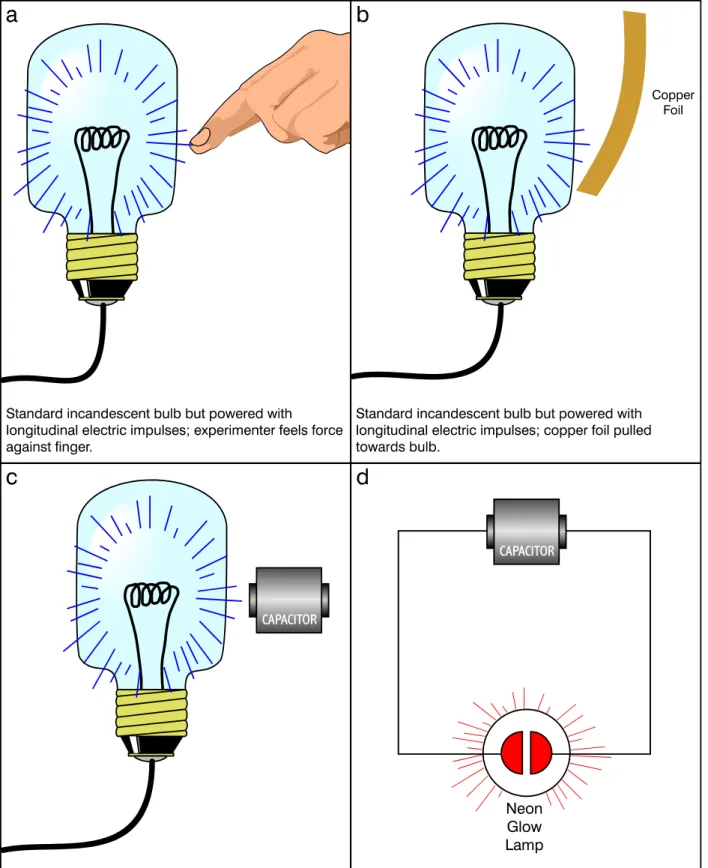
3.3.5 Unique Characteristics of Longitudinal Electricity ... 48
3.3.6 Demonstration of Tesla's Radiant Energy Patents... 51
3.3.7 Long-Range Longitudinal Wave Transmission ... 53
Contents (Cont'd)
Page
3.4 Scalar Waves... 53
3.4.1 Introduction... 53
3.4.2 Dr. Thomas Valone's Writings on Scalar Waves... 54
3.4.3 Dr. Konstantin Meyl's Teachings on Scalar Waves... 57
3.4.4 The Polarization Synchrotron ... 62
4. BREAKTHROUGH ENERGETICS—ZERO POINT ENERGY ... 65
4.1 Introduction and Overview ... 65
4.2 Accessing or "Tapping" Energy from Zero Point Energy ... 65
4.2.1 Specific Disclaimer Regarding ZPE Plausibility... 65
4.2.2 ZPE Credibility Breakthrough ... 66
4.2.3 ZPE Access Principles Stated by Moray King ... 66
4.2.4 Dr. Thomas Valone's Overview of ZPE Approaches ... 67
4.3 Zero Point Energy Principles in the Similar Technologies of Nikola Tesla and E.V. Gray ... 69
4.3.1 Dr. Peter Lindemann... 69
4.3.2 ZPE Principles Suggested in E.V. Gray's Technology ... 69
4.3.3 The Energy Science of Dr. Nikola Tesla ... 69
4.3.4 Dr. Lindemann's Definition of "The Electro-Radiant Event"... 72
4.3.5 Comparing E.V. Gray's Technology with that of Tesla... 73
4.3.6 Summary of Principles for Accessing ZPE ... 77
4.4 Additional Inventions and Discoveries Claiming "Excess" Energy ... 77
4.4.1 Introduction... 77
4.4.2 Disclaimer ... 77
4.4.3 The Papp Engine ... 77
4.4.4 The Graneaus' Water Arc Explosion Experiments ... 78
4.4.5 Dr. T. Henry Moray's Energy Device ... 79
4.4.6 Summary ... 80
5. OTHER RESEARCH RELEVANT TO ADVANCED ENERGETICS... 81
5.1 Introduction... 81
5.2 The Fourth Law of Motion ... 81
5.2.1 Introduction... 81
5.2.2 Specific Disclaimer for the Fourth Law of Motion ... 81
5.2.3 The Origin of the Fourth Law... 82
5.2.4 Nonsimultaneity... 83
5.2.5 Third Derivative Equations of Motion... 83
5.2.6 Third Derivative Reactionless Propulsion System ... 83
vi
Contents (Cont'd)
Page
5.2.7 Overview of Patented Reactionless Propulsion Devices ... 84
5.2.8 Analogy with Work Produced by Electrical Alternating Current... 84
5.2.9 Statement of the Fourth Law of Motion ... 85
5.3 The Scientific Theories of Edwin Yates Webb, Jr... 85
5.3.1 Introduction... 85
5.3.2 Specific Disclaimer for Webb’s Theories... 85
5.3.3 Webb’s Electric Field Interpretation of Matter and Energy ... 85
5.3.4 Webb’s Analysis of the Null Results of Classical Aether Detection Experiments ... 85
5.3.5 Consequences of Removing the Aether from 20th Century Theoretical Physics ... 87
5.3.6 Webb’s Theory of Gravity... 87
5.3.7 Comments on Webb’s Theory of Gravity... 88
5.4 Condensed Matter Nuclear Science ... 89
5.4.1 General Background and Introduction... 89
5.4.2 Disclaimer for Condensed Matter Nuclear Science... 89
5.4.3 Electrochemically Induced Deuterium Fusion in Palladium ... 89
5.4.4 The ICCF-10 Paper by Drs. Dennis G. Letts and Dennis J. Cravens, "Laser Stimulation of Deuterated Palladium: Past and Present" ... 90
5.4.5 The ICCF-10 Paper by Dr. Yasuhiro Iwamura, et al., "Low Energy Nuclear Transmutation in Condensed Matter Induced by D2 Gas Permeation through Pd Complexes: Correlation Between Deuterium Flux and Nuclear Products" ... 90
5.4.6 The ICCF-10 Paper by H. Yamada, et al., "Analysis by Time-of-Flight Secondary Ion Mass Spectroscopy for Nuclear Products in Hydrogen Penetration through Palladium" ... 91
5.5 High Frequency Gravitational Waves... 92
5.5.1 Introduction... 92
5.5.2 Disclaimer for HFGWs ... 92
5.5.3 Extreme Weakness of Gravity and GWs ... 92
5.5.4 GWs ... 92
5.5.5 HFGWs ... 93
5.5.6 Applications of HFGWs ... 93
5.5.7 Selected HFGW Conference Papers ... 93
6. CONCLUSIONS ... 95
7. REFERENCES ... 97
Figures
Page 1. Conceptual Design and Placement of P/P and Other Components for the NASA-LaRC/
MSE Emissionless Aircraft... 6
2. Schematic of a Planar SOFC...10
3. PSOFC P/P System...18
4. The CBFR-SPS ...23
5. IEC Fusion Power Generator Concept...36
6. Electric Field of Conductor. Lines of Magnetic Force are Shown Solid; Lines of Dielectric Force are Shown Dotted...45
7. Electric Field of Circuit. Lines of Magnetic Force are Shown Solid; Lines of Dielectric Force are Shown Dotted...45
8. Experiments with Standard Incandescent Bulbs Powered by Longitudinal Electric Impulses ...50
9. Flat Spiral Coil for Transmitting/Receiving Longitudinal Electric Waves (Not To Scale)...52
10. Technologies of Tesla and Gray and Common Features of Both...74
Tables Page 1. PSOFC Metal Plate Deflections vs. Metal Plate Thickness ...11
2. PSOFC P/P System and Modified CBFR System Component Weights ...26
viii
Acronyms and Abbreviations
2-D two-dimensional 3-D three-dimensional
ac alternating current
atm atmosphere (measurement)
B11 most common boron isotope with atomic weight 11 BSRF Borderland Sciences Research Foundation
Btu British thermal unit
°C degree Celsius
CBFR Colliding Beam Fusion Reactor
CBFR-SPS Colliding Beam Fusion Reactor Space Propulsion System CL lift coefficient
cm centimeter
CNT carbon nanotube
CR contractor report
Cµ momentum coefficient
CW continuous wave
dc direct current
DEC direct energy converter EM electromagnetic
°F degree Fahrenheit
FLOPS Flight Optimization System ft foot/feet
G acceleration equivalent to the acceleration of gravity at the surface of the Earth
GaSb gallium antimonide
GE General Electric
GECAT Graphical Engine Cycle Analysis Tool
GH2 gaseous hydrogen
gpm gallons per minute
GTE gas turbine engine
GW gravitational wave
H1 hydrogen
Acronyms and Abbreviations (Cont'd) Hz hertz
He4 helium 4
HFC hydrogen fuel cell
HFGW high frequency gravitational wave hp horsepower
ICCF International Conference on Cold Fusion ICP-MS inductively coupled plasma-mass spectrometry IEC Inertial Electrostatic Confinement
ID inside diameter
in inch INE Institute of New Energy
IRI Integrity Research Institute
K degree Kelvin
kg kilogram kHz kilohertz kPa kilopascal kV kilovolt kW kilowatt kWh kilowatt-hour L length lb pound L/D lift-to-drag LENR low energy nuclear reaction LFGW low frequency gravitational waves
LH2 liquid hydrogen
LHe liquid helium
LMD longitudinal magneto-dielectric (waves) m meter
m2 square meter
MEMS micro-electromechanical systems
MeV megaelectronvolt
x
Acronyms and Abbreviations (Cont'd) mH millihenry
MHz megahertz min minute mm millimeter
MSE MSE Technology Applications, Inc.
MW megawatt
NASA National Aeronautics and Space Administration NASA-LaRC NASA Langley Research Center
Nb3Sn niobium-tin (superconductor wire) NEPP NASA Engine Performance Program
NIST National Institute of Standards and Testing
nmi nautical mile
OD outside diameter
P/P power/propulsion psi pound per square inch
PSOFC planar solid oxide fuel cell
PV polarizable vacuum
R rankine
Re Reynolds number
RF radio frequency
s second SOFC solid oxide fuel cell
TEC thermoelectric converter
TEM transverse electromagnetic (waves)
TOF-SIMS time of flight secondary ion mass spectrometry TPV thermophotovoltaic
µF microfarad USAF U. S. Air Force
V volt W watt ZPE zero point energy
xii
Executive Summary of This Project Prior to This Report
The National Aeronautics and Space Administration (NASA) has identified water vapor
emission into the upper atmosphere from commercial transport aircraft, particularly as it relates to the formation of persistent contrails, as a potential environmental problem. Since 1999, MSE Technology Applications, Inc. (MSE) has been working with the NASA Langley Research Center (NASA-LaRC) to investigate the concept of a transport-size emissionless aircraft fueled with liquid hydrogen (LH2) combined with other possible breakthrough technologies. The goal of the project is to significantly advance air transportation in the next decade and beyond. The power/propulsion (P/P) system currently being studied would be based on hydrogen fuel cells (HFCs) powering electric motors, which drive fans for propulsion. The liquid water reaction product is retained onboard the aircraft until a flight mission is completed.
As of now, NASA-LaRC and MSE have identified P/P system components that, according to the high-level analysis conducted to date, are light enough to make the emissionless aircraft concept feasible. Calculated maximum aircraft ranges (within a maximum weight constraint) and other performance predictions are included in this report.
Carrying liquid water reaction product onboard for the duration of a flight mission imposes a severe weight penalty. If modeling and experiments show that water may be expelled as liquid droplets of an appropriate size and temperature and will not significantly reevaporate in the higher atmosphere nor freeze and form hailstones when falling through the lower atmosphere, the resulting weight relief would greatly accelerate the practical realization of this project. A preliminary calculation showing the magnitude of the resulting benefit of this weight reduction is included in this report.
Even though near-term technology allows for a plausible concept for an emissionless aircraft and therefore a solution to the high-altitude water vapor problem, more advanced technologies presently being investigated in research laboratories may potentially offer more practical solutions. For example, advanced aerodynamics could potentially extend the fuel efficiency of any aircraft; this report describes some leading examples of this type of research.
In the midterm, recently discovered types of nuclear reactions that do not produce penetrating radiation may offer fuel energy densities approximately one million times greater than that of chemical fuels. Examples of these reactions are described. Additionally, recently discovered methods for converting heat to electricity, transferring heat, and storing energy are discussed.
In the long-term, technologies that can only be described as "breakthrough" may potentially be available for producing energy from the very structure of space-time itself or propelling vehicles without using a material propellant to balance momentum. Present research being conducted at multiple locations around the world indicates such technologies may be possible, and this research is presented.
Finally, some topics of "breakthrough physics," which typically precede "breakthrough technology," are presented at an introductory level.
Executive Summary of This Report
The National Aeronautics and Space Administration (NASA) has identified water vapor
emission into the upper atmosphere from commercial transport aircraft, particularly as it relates to the formation of persistent contrails, as a potential environmental problem. As a possible solution to this problem, a revolutionary aircraft concept (based upon liquid hydrogen fuel, high temperature fuel cells, electric motors driving fans for propulsion, and retention of reaction product water) was developed, verified with NASA computational flight codes (using stated assumptions) to be a valid concept, and published as NASA/CR-2003-212169. A continuation and extension of that research is published herein; previous conclusions regarding the feasibility of this project remain valid. Applicable near-term concepts described in this current report include: 1) expulsion of reaction product water in a form or by a method that will not harm the environment, 2) using water expelled as vapor (below a "critical" altitude) to augment aircraft propulsion thrust, 3) fabricating planar solid oxide fuel cells (PSOFCs) from materials that could potentially yield a significantly higher electric power density (kilowatt/kilogram), and 4) using the aerodynamic concept known as "circulation control" to extend aircraft range by providing a better match between cruise and takeoff/landing requirements. In addition, conceptual
emissionless aircraft performance parameters have been calculated using actual PSOFC electric power density and electrochemical efficiency data from a company that fabricates these devices.
A major limitation to the performance of a conventional aerospace vehicle is the weight of the fuel. Therefore, MSE Technology Applications, Inc. (MSE) investigated revolutionary and breakthrough power production technologies that could potentially allow the creation of aerospace technology far surpassing the state of the art. Such technology (conceptually
examined by MSE) includes two distinctly different categories of flight weight fusion reactors.
One of these systems is characterized by a radial electric field in a spherical shape; the other is based upon a cylindrical-shaped magnetic field. Both systems react common inexpensive fuels in a plasma state and produce reaction product ions with a very high kinetic energy but do not produce neutrons (or penetrating radiation) or residual radioactive components. The kinetic energy of these fast-moving charged ions produced in these fusion reactions may be readily converted to electric power by known methods. These revolutionary fusion power systems would increase fuel energy density (kilowatt-hour/kilogram) by a factor of approximately one million compared to chemical fuels, and they would be totally emissionless and safe.
As part of this research and at the invitation of NASA Langley Research Center, MSE
investigated advanced energetics topics of a more long-term nature. Selected electric concepts such as a deeper understanding of the components of the "electric field," longitudinal electric waves, and scalar waves as well as other advanced physics concepts that are replicable (but not widely known) were examined. Some of these could potentially be developed into advanced power and propulsion technologies or even help access zero point energy, which has a basis firmly established in theoretical physics and a calculated energy density many orders of magnitude greater than currently used sources of energy.
Several additional selected topics in advanced physics (including condensed matter nuclear science and high frequency gravitational waves) were also investigated in order to provide increased understanding of and further insights into some of the research mentioned above.
2
General Disclaimer
The content of "Advanced Energetics for Aeronautical Applications," both prior and current work, should be considered as a "work-in-progress."
What is reported reflects the current status of investigations and analysis on selected topics.
1. Potential New Aeronautical Energetic Requirement⎯The "Emissionless Aircraft"⎯Updated Investigations and Innovations
1.1 Emissionless Aircraft Conceptual Model at the Conclusion of Work Prior to This Report
This section summarizes, in somewhat more detail, the status of the "application side" of the Advanced Energetics for Aeronautical Applications when the prior work was published.
1.1.1 Status of Project Investigations when Prior Work was Published
The following excerpt from the Conclusions section of the prior work is quoted as an introduction to this report.
There is now convincing evidence to support observations that water vapor emission into the atmosphere at altitudes above 25,000 ft by conventional hydrocarbon-fueled aircraft is changing climate patterns in local regions,
possibly adversely through the formation of contrails. However, the extent of the effect has not been fully determined.
Starting with the guideline that any feasible approach could be investigated and considered, and the research performed to date, MSE has determined that a near- emissionless 300 passenger commercial transport aircraft capable of flying substantial distances is conceptually possible. This conclusion was reached by a logical process of eliminating approaches considered to be impractical and assuming there will be modest gains made in areas of technology such as component weight reduction, energy conversion power density, and advanced aeronautics. A numerical analysis based upon the NASA-LaRC FLOPS code, (modified for this application) was used to calculate estimated maximum ranges of the conceptual emissionless aircraft. This analysis, including the energy conversion and aerodynamic assumptions that went into the calculations as well as the calculated ranges and some of the other parameters that are code outputs, have been reported during the course of this study and included herein.
The emissionless aircraft concept developed by MSE would use a novel
combination of the following technologies, all of which have been developed as hardware (to some degree):
− LH2 fuel carried in insulated tanks;
− high temperature PSOFCs to generate electricity by combining hydrogen with oxygen from ambient air;
− bottoming cycle GTEs coupled to generators to convert heat in the fuel cell exhaust gas into additional electric power;
− ultralight, ultraefficient cryogenic electric motors, coupled to fans, to provide propulsion;
4
− advanced aeronautical technology to maximize the L/D ratio in order to maximize aircraft range;
− lightweight, high-strength materials to fabricate appropriate aircraft
components, to minimize empty weight and therefore maximize aircraft range;
and
− novel advanced, lightweight heat transfer technology to remove heat from water vapor produced during flight so that water vapor may be condensed to a liquid and stored onboard for the remainder of a flight mission.
All of the above technologies have been investigated and reported on by MSE Technology Applications, Inc. (MSE) and are included in this report.
A tentative geometric configuration of major components and systems of the emissionless aircraft was devised within the constraints of technical parameters as currently known.
It was also concluded that if liquid water reaction product could be immediately expelled as liquid droplets of an appropriate size and temperature and would cause no adverse effects either in the atmosphere or on the ground, the resulting weight relief would greatly accelerate the project.
1.1.2 Conceptual Design and Component Placement
Figure 1 illustrates the conceptual design and placement of power/propulsion (P/P) and other components for the National Aeronautics and Space Administration Langley Research Center (NASA-LaRC)/MSE emissionless aircraft.
1.1.3 Calculated Maximum Emissionless Aircraft Ranges
Finally, it is noted that prior work indicated that the calculated range of the emissionless aircraft described by this concept would be 2,568 nautical miles (nmi) for conservative near-term assumptions and as far as 10,715 nmi using long-term assumptions (i.e., technology that is plausible but not yet developed).
1.2 Potential Planar Solid Oxide Fuel Cell Weight Reduction 1.2.1 Introduction
As described previously, planar solid oxide fuel cells (PSOFCs) are the primary source of electric power in the state-of-the-art conceptual emissionless aircraft being investigated.
Therefore, it is obvious that any innovation that will increase the density of produced electric power kW
kg
⎛
⎝⎜ ⎞
⎠⎟from the aircraft PSOFCs will be of benefit to ensure project feasibility.
6
Forward H
2O Tank
Aft H
2O Tank Forward
LH
2Tank
Aft LH
2Tank Passenger
Compartment Fuel Cell
Air Intake
Compressors
Fuel Cells
Power Turbines
Cooling Air Intake
Exhaust-Air and Exhaust-H
2HXs
Figure 1. Conceptual design and placement of P/P and other components for the NASA-LaRC/MSE emissionless aircraft.
In order to decrease PSOFC weight, MSE postulated that the stacked plates (and exterior shell) of prototype PSOFCs currently manufactured from traditional stainless steels could instead be potentially produced from the specially developed "superalloys" from which the "hot"
components of conventional aircraft turbine engines are produced.
The densities of standard stainless steels and superalloys are similar. It is suggested that (in the PSOFC interior), superalloy metal plates could be significantly thinner than those currently produced from standard stainless steel and that a significant saving in weight and volume would result.
1.2.2 Background Information
NASA-LaRC and MSE had assumed the following PSOFC parameters for aircraft system performance calculations reported in a recent NASA Contractor Report (CR) (Ref. 1, p. 24):
• PSOFC electrochemical efficiency:
− near-term: 50% cruise, 60% descent; and
− long-term: 60% cruise, 70% descent.
• PSOFC power density (weight basis):
− near-term: 1,102 pounds/megawatt (lb/MW) [(2 kilowatt (kW)/kilogram (kg)]; and
− long-term: 100 lb/MW.
Using these assumed weight-basis power densities, the calculated weight of PSOFCs for the respective near- and long-term scenario assumptions are as follows (Ref. 1, pp. 25-26):
− near-term: 86,139 lb; and
− long-term: 7,975 lb.
Two important points concerning these weights are:
1) Based upon PSOFC parameters known at the time of the previous analysis, no
"overrating" of PSOFCs for the climb phase of a flight is allowed compared to the power requirement of the cruise phase of a flight. Therefore, the above weights are sized for the required climb power level.
2) It was assumed for the above-referenced calculations that higher weight reductions were not possible for PSOFCs by substituting (e.g., carbon nanotubes (CNTs) for metals) due to the hot and oxidizing environment.
1.2.3 PSOFC Parameters
One company developing PSOFCs uses circular metal plates with alternate plates coated on one side with a thin layer of a proprietary catalytic oxide material. The plates are sealed to each other over a small radial distance at the center. Spiral grooves on the uncoated plates direct fuel (hydrogen, which enters from the center) and oxidizer (air, which enters from the periphery) respectively. Prototype cells use plates with a 5-inch (in.) diameter. The important parameters relevant to the present investigation are:
− plate material—stainless steel (exclusive of oxide coating); and
− plate thickness—0.083 in.
Additionally, it is noted that:
− the particular alloy of stainless steel used for these plates was not stated;
− these plates were quite rigid (not flexible) at ambient temperature; and
− because the PSOFCs were laboratory prototypes, there has not yet been an attempt by the vendor to increase the weight-basis power density (i.e., reduce the weight).
1.2.4 PSOFCs Based Upon Superalloys
One can suggest that the metal plates used in this type of PSOFC could be metals specifically designed to maintain dimensional tolerances and strength at significantly high temperatures [e.g., the "nickel superalloys" used in the hot sections of gas turbine engines (GTEs)].
There has been considerable research and development of these types of metals, originating as long ago as 1930. These alloys are created by adding selected combinations of metallic and nonmetallic chemical elements (from a list of 19 elements) to a "base" of nickel and then using advanced processing techniques. Such alloys are used to fabricate turbine blades where they must maintain dimensional tolerances while being subjected to high (centrifugal) force and the high temperatures experienced in the turbine section of a GTE (Ref. 2).
The following assumptions can be used when considering to what extent metal weight may be reduced in PSOFCs by using superalloys instead of ordinary stainless steel.
1) The operating temperature inside PSOFCs has been stated to be on the order of 650 degrees Celsius (°C) (or less).
2) The proprietary solid oxide catalytic material will adhere to superalloys as well as it does to stainless steel.
3) There are no adverse chemical, electrical, or electrochemical effects that would occur if stainless steel were replaced with superalloys.
4) Most of the PSOFC weight is from the metal, and "shell" components (also fabricated from superalloys) can have their weight reduced by the same proportion as for cell plates.
8
Based on the extremely high strength at high temperatures of the nickel-based superalloys, one can postulate that PSOFC plates could be one-fourth the thickness of prototype plates now made from stainless steel. Therefore, because stainless steel and superalloys have nearly equal specific gravities (~8.0) and, using the above-stated assumptions, this is equivalent to stating that in the near-term the PSOFC weight-basis power density is 8.0 kW/kg (equivalent to 276 lb/MW).
1.2.5 Plate Bending and Plasticity Analyses
After initially suggesting that the metal plates in PSOFCs could be significantly thinner if produced from superalloys rather than standard stainless steel, MSE performed both plate bending and plasticity analyses on currently used ceramics and superalloys suggested for the PSOFC application. The results of these analyses are presented in this section.
The goal of this work was to attempt to realistically calculate the extent that metal plate components of PSOFCs could be reduced in thickness.
When a PSOFC heats from room temperature to operating temperature, any mismatch in coefficients of expansion of internal components will create stress in these components. The amount of stress would be proportional to an amount of bending (deflection) of these respective components if they were not constrained. It is readily possible to calculate material deflection by using:
− known internal geometric configurations of PSOFCs;
− properties of PSOFC materials; and
− standard, accepted methods of performing such calculations.
1.2.6 Calculation Method for Plate Bending and Plasticity Analyses
The fuel cell plates were modeled using ANSYS finite element software. Axisymmetric elements, representing the metal disk and the ceramic layer on one side of the metal disk were used. The stress is induced by the difference in the thermal expansion coefficients of the metal and the ceramic materials. Therefore, the analysis was performed by applying a uniform temperature of 650 ºC and comparing the stress and deflection in the metal plate for several different plate thicknesses (for a constant ceramic thickness between the plates).
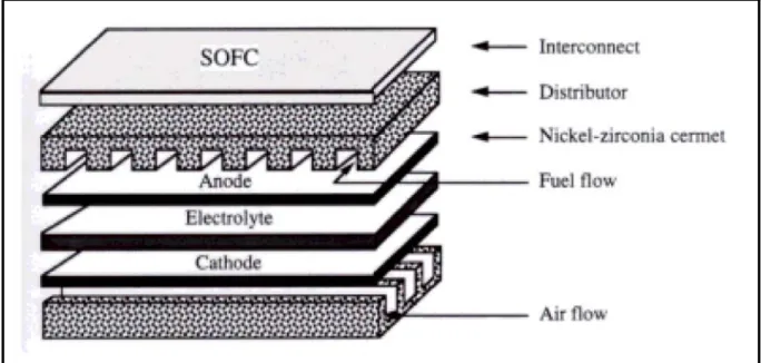
It is understood that "ceramic" refers to a multilayer "sandwich" configuration of nickel-zirconia cermet as the anode (fuel side), yttria stabilized zirconia in the middle as the electrolyte (which conducts oxygen anions), and lanthanum strontium manganate as the cathode (air side). A schematic of another type of PSOFC, illustrating these layers, is shown in Figure 2 (Ref. 3).
These three materials are produced with different controlled porosities and have similar thermal expansion coefficients [for another type of solid oxide fuel cell (SOFC)] as follows (Ref. 4):
− anode layer—12.5 x 10⁻⁶ centimeter (cm)/cm per degrees Celsius;
− electrolyte layer—10.5 x 10⁻⁶ cm/cm per degrees Celsius; and
− cathode layer—11 x 10-6 cm/cm per degrees Celsius.
Figure 2. Schematic of a planar SOFC.
For the purposes of this report, this multilayer ceramic structure will be referred to as the
"ceramic."
Note that type 301 stainless steel was the representative material used in this analysis, as there are more available property data for type 301 in current references than for other types of stainless steel.
Similarly, Rene 41 was the representative nickel-based superalloy used in this analysis, as there are more available property data in current references than for other types of alloys in the nickel- based "superalloy" family.
Additional material properties (type 301 stainless steel, Rene 41 superalloy, and yttria stabilized zirconia ceramic) that went into the ANSYS calculations were from standard references (Refs. 5, 6, and 7).
1.2.7 Calculation Assumptions
The following parameters and assumptions were included in the deflection calculations explained in the preceding section:
− initial temperature—0 °C (ambient);
− operating temperature—650 °C;
− ceramic properties—those for zirconium oxide stabilized with yttrium oxide (yttria stabilized zirconia) (there are other ceramic components that have similar properties);
− ceramic thickness—0.01 in. in all cases;
− metal plate thickness—0.08, 0.04, 0.02, and 0.01 in (four thicknesses analyzed);
− geometric shape—circular plates;
10
− interface—ceramic tightly bonded to one side of metal plate;
− plate diameter—5 in;
− center constraint—the plate has a 1-in-diameter hole at its center on which it is rigidly mounted to the rest of the fuel cell assembly; constraint is three dimensions [X, Y, Z axes (for gas seals)];
− edge constraint—the plate has a 5-in. outside diameter (OD) and the outside edge is unconstrained;
− baseline metal—type 301 stainless steel; and
− high temperature metal—Rene 41 nickel alloy.
1.2.8 Calculation Results
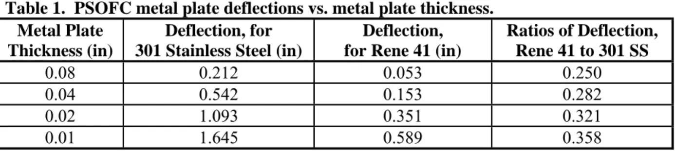
The results of the calculations are presented as deflection of the metal plate edge vs. metal plate thickness (for each respective metal) at a temperature of 650 °C, as well as the ratio of these deflections. The deflections resulted in the ceramic being on the "concave" side and metal being on the "convex" side of the resulting shape because each metal has a higher thermal expansion coefficient than ceramic. These values are presented in Table 1 below.
Table 1. PSOFC metal plate deflections vs. metal plate thickness.
Metal Plate Thickness (in)
Deflection, for 301 Stainless Steel (in)
Deflection, for Rene 41 (in)
Ratios of Deflection, Rene 41 to 301 SS
0.08 0.212 0.053 0.250
0.04 0.542 0.153 0.282
0.02 1.093 0.351 0.321
0.01 1.645 0.589 0.358
1.2.9 Preliminary PSOFC Plate Bending Analysis Conclusions
As shown in Table 1, the ratio of deflection of Rene 41 to an equal thickness of type 301 stainless steel is one-quarter for the thickest dimension analyzed to approximately one-third for the thinnest dimension. These would be for an unconstrained situation but imply that in the (PSOFC stack) constrained situation the stainless steel plates could be conceptually replaced with Rene 41 plates approximately one-quarter to one-third as thick. Since the specific gravities (densities) of these respective metals are similar, this would result in a considerable weight savings (provided there are no adverse effects resulting from making such a change).
However, there is a significant problem associated with "plasticity" because in all the cases analyzed, the thermally induced stresses exceeded the yield strength of the metal through the cross-section in at least a portion of the disk. The meaning of this is that (for any material) when the force divided by a cross-sectional area (stress) exceeds the yield strength (which varies with temperature), the dimensions of the material will not return to the starting values when this stress is released (i.e., the material will be permanently stretched or deformed).
It is to be expected that (with temperature cycling) this condition would eventually lead to a separation of the ceramic-metal bond that would cause fuel cell degradation or failure.
The preliminary conclusion from the plasticity analysis (as well as the plate bending analysis which preceded it) is that the ceramic and metallic thermal expansion coefficients should match to the greatest extent possible.
1.2.10 Potential PSOFC Metals
A preliminary search of a materials property database resulted in 144 metals with thermal
expansion coefficients (in the PSOFC operational temperature range) within a few percent of the ceramic thermal expansion coefficient used in the calculations described in the preceding
sections (Ref. 8).
A preliminary analysis indicates many (but not all) of these metals are titanium alloys. It is understood that chemical and other properties will eliminate many potential candidate metals (e.g., an alloy constituent may migrate into the ceramic layers, over a period of time, driven by the operating temperature and electric field between the layers).
1.3 State-of-the-Art Vendor-Supplied Planar Solid Oxide Fuel Cell Parameters 1.3.1 Introduction
It was previously assumed that PSOFCs had a constant upper limit (weight basis) power density (i.e., could not be overrated for the climb portion of a flight mission). Therefore, PSOFC weight was sized for the approximately 84 MW required for the climb portion of the flight mission, whereas most of the PSOFC weight would then be excess for the much longer cruise phase of a flight mission. MSE has had recent extensive technical discussions with a company that
manufactures PSOFCs, and the present understanding is that PSOFCs may be significantly overrated for the climb portion of a flight mission (though at reduced electrochemical efficiency). This report analyzes the consequences of this new information.
1.3.2 Updated PSOFC Parameters
MSE has recently discussed a performance map for PSOFCs operating with hydrogen as fuel and air as oxidizer with a company that develops and manufactures this technology (Ref. 9).1 For the present analysis, the two relevant parameters are (weight basis) power density and
electrochemical efficiency. As with any other electrochemical power production technology, there is an approximately inverse relationship between power density and efficiency.
After MSE explained the P/P requirements of the conceptual MSE/NASA-LaRC emissionless aircraft, the PSOFC manufacturing company stated the following:
1 Joseph Hartvigsen, Ceramatech, Inc., December 12, 2003.
12
• Cruise electrochemical efficiency is 55%; the (weight basis) power density (after climb and before descent) is 1 kW/kg.
• The (weight basis) power density (for the relatively short duration of climb) can be as high as 3.33 kW/kg. At this power density, the electrochemical efficiency is 25%. (MSE assumes the actual electrochemical efficiency can be linearly interpolated between 55% at 1.00 kW/kg to 25% at 3.33 kW/kg.)
• Descent electrochemical efficiency is 65%; the (weight basis) power density could be as high as 0.83 kW/kg and maintain this level of electrochemical efficiency (but in fact the required power density for descent is significantly less).
1.3.3 Discussion of Updated PSOFC Parameters
The updated PSOFC parameters are considered current state of the art (near term) and imply the following changes (compared to PSOFC parameters previously used by MSE and NASA-LaRC):
• The cruise-phase electrochemical efficiency is 55% (it had previously been 50%).
• The basic (long-duration, weight-basis) power density is 1 kW/kg (it had been 2 kW/kg).
• The climb-phase power level can be increased as much as 3-1/3 times or 333% (no such overrating was previously assumed possible).
• The electrochemical efficiency will decrease to 25% for the climb phase of the flight mission if the full 333% overrating is used. (MSE and NASA-LaRC are assuming now that the actual efficiency may be linearly interpolated (e.g., if the overrating is 267%, then the efficiency reduction will be 80% of (55% minus 25%) or 24%), thereby resulting in an electrochemical efficiency of 31% (i.e., 55% minus 24% is 31%).
• The descent phase of the flight mission could use as much as 83% of cruise power at an electrochemical efficiency of 65% (it had previously been 60%).
Obviously one big change based on the updated parameters is that the onboard weight of PSOFCs can be sized for cruise conditions (rather than climb conditions), which means
considerable extra weight used for approximately 20 minutes (min) does not have to be carried for the duration of a long flight.
1.3.4 Updated Flight Optimization System Code Calculations
NASA-LaRC used the updated PSOFC parameters described above and recalculated the following:
− climb, cruise, descent, and total maximum range for emissionless operation (reaction product water stored onboard);
− climb, cruise, descent, and total maximum range for the water-emitting mode;
− onboard weight of PSOFCs; and
− power levels required for climb and cruise for both emissionless and water-emitting scenarios.
To clearly show the result of using these updated PSOFC parameters, Flight Optimization
System (FLOPS) calculations were performed similar to those performed as described in a recent NASA CR (Ref. 1, pp. 22-35) (i.e., potential (weight basis) power density increases caused by innovative fuel cell materials were excluded).
1.3.5 Procedure Used for FLOPS Code Calculations
Some of the items to be noted in the procedure used by NASA-LaRC to calculate aircraft ranges based on the updated PSOFC parameters are given below.
• The analysis had to be repeated a few times before proper convergence could be obtained.
• Planar solid oxide fuel cell weight was sized for cruise conditions (as explained above).
• The full 333% surge capability of the PSOFCs was not needed.
• There is a slight reserve of available power (for the climb phase of a flight mission) for both the emissionless and emitting scenarios.
• It was assumed that PSOFC power generation would instantly change from climb to cruise levels. In practice, there would be a transition; however, MSE and NASA-LaRC believe there would be no significant change in the calculation resulting from the extra
computational effort.
1.3.6 FLOPS Code Results with Updated PSOFC Parameters
Using the updated PSOFC parameters and the NASA-LaRC FLOPS Code, the updated calculated ranges for emissionless operation are as follows:
− climb: 123 nmi
− cruise: 2,860 nmi
− descent: 225 nmi
− total: 3,207 nmi
The updated calculated ranges for water-emitting flight are as follows:
− climb: 147 nmi
− cruise: 18,759 nmi
− descent: 224 nmi
− total: 19,130 nmi
It should be noted that 19,130 nmi is approximately 89% of the distance around the Earth.
The required onboard weight of PSOFCs (calculated by the FLOPS Code) is 76,548 lb.
14
The required power levels are as follows:
− emissionless climb: 87.5 MW
− emissionless cruise: 31.4 MW
− emitting climb: 95.4 MW
− emitting cruise : 29.3 MW
1.3.7 Discussion of Updated Calculated FLOPS Results The updated PSOFC parameters result in the following changes:
− total range for the emissionless scenario has increased 25%;
− total range for the water-emitting scenario has increased 27%;
− onboard PSOFC weight has decreased 11%;
− emissionless climb power has increased 4%; and
− emissionless cruise power has decreased 3%.
1.4 Controlled Water Expulsion
1.4.1 Introduction—Water Expulsion—Major Parameters Needing Investigation
Because of the very significant increase in calculated range when reaction product water does not need to be retained onboard the aircraft (for a transport aircraft fueled with hydrogen that is electrochemically reacted with atmospheric oxygen to produce water), MSE and NASA-LaRC conducted further investigations into water expulsion scenarios. Some of the major parameters identified to date are listed (some of these parameters will be discussed in more detail
subsequently).
1) Critical Altitude
Above the critical altitude, it is important to prevent (or at least minimize) the introduction of water vapor. Below this altitude, the introduction of water vapor is not considered to be an environmental problem. As mentioned above, NASA-LaRC has recently stated that the critical altitude is 27,000 feet (ft). It is noted that this altitude is not constant but nominal (i.e., it can vary as a function of weather conditions).
2) Aircraft Cruise Altitude
Typical emissionless aircraft cruise altitudes (optimized for maximum aircraft range by NASA-LaRC with the NASA FLOPS Code) were in the range of approximately 39,000 to 43,000 ft (varying as a function of aircraft weight). Commercial airlines operate
conventional GTE-powered transport aircraft at cruise altitudes that are typically 35,000 ft, plus or minus several thousand feet. This is because GTEs operate most efficiently (for the cruise part of a flight mission) at such altitudes.
If transport aircraft powered with hydrogen fuel electrochemically reacted in fuel cells were flown at a cruise altitude of 27,000 ft, water could be emitted as vapor and there would be no harm to the environment.
If it is determined that an HFC-powered transport aircraft should have a cruise altitude (significantly) higher than 27,000 ft, then expulsion of water as vapor may not be an option for an aircraft designed to protect the environment.
3) Water Phase and Particulate Size at Expulsion (if cruise altitude is higher than the critical altitude)
If water could not be emitted as vapor, then should the water be solid or liquid? In addition, what would the optimum particulate size be in order to minimize reevaporation while falling down to 27,000 ft and cause no damage when reaching the ground (i.e., be the same or very similar to ordinary rain or snow)?
1.4.2 The Advantages of Water Expulsion as Vapor
If water (produced by the electrochemical reaction of hydrogen fuel) could be expelled from a large transport aircraft as vapor, there would be significant advantages.
1) The weight savings by not carrying (liquid) water to the conclusion of a flight mission would be highly significant (as previously mentioned).
2) Heat exchangers (and their associated weight) would not be required to condense water vapor.
3) As previously discussed, product water tanks (and their associated weight) would not be required.
4) The exhaust from the small turbines, which recover additional energy from the fuel cell exhaust gas, can now be used for thrust. This is not possible when the exhaust from these turbines must be slowed down in heat exchangers that are required to condense water vapor to liquid (or solid) water. A more detailed discussion of this scenario and the thrust
calculations is included in Section 1.5.
1.5 Thrust Produced by Power Recovery Turbine Exhaust
1.5.1 Introduction
Recognizing that if an HFC-powered transport aircraft maintained a cruise altitude no higher than 27,000 ft and therefore the exhaust from the power recovery turbines could be used to directly provide thrust, an effort was made to calculate the level of this thrust.
16
1.5.2 Thrust Calculation
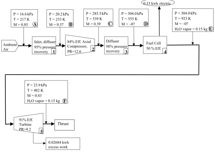
Using the PSOFC P/P system block flow diagram and its previously calculated values as a starting point, MSE calculated the total amount of exhaust thrust available from the four power recovery turbines (Figure 3). This was done for the stated conditions on the block flow diagram (representing a cruise altitude of approximately 42,000 ft) and then repeated for the conditions at a cruise altitude of 27,000 ft.
The procedures used to calculate the thrust from the energy recovery turbine exhaust are summarized as stated below.
An emissionless aircraft core engine thrust was estimated using the Graphical Engine Cycle Analysis Tool (GECAT). GECAT’s core computational code is the NASA Engine Performance Program (NEPP). The model constructed in GECAT was built using generic compressor and turbine maps and is a first attempt at estimating the amount of thrust that is possible in the core engine flow. The design point for the core engine was built using the conditions shown in the PSOFC P/P system flowchart. These conditions correspond to an altitude of 43,173 ft, flight Mach number of 0.85, and core engine airflow of 61 lb/second (s). The fuel cell power extraction was simulated using a hydrogen-fueled main burner and turbine shaft load. The turbine shaft load was increased until the desired turbine exit enthalpy was reached.
After a reasonable result was obtained from the design point calculations, an off-design calculation was performed at an altitude of 27,000 ft with the following assumptions:
− the fuel cell does not operate at constant inlet pressure;
− the turbine shaft load is constant (excluding the compressor horsepower); and
− the turbine entrance temperature is equal to the design point [1,661 Rankin (R)].
It is recognized that using a GTE computational code to calculate results when a fuel cell is (conceptually) integrated with a GTE is quite nonconventional. Nevertheless, at this time, NASA-LaRC and MSE believe the thrust calculations are reasonably accurate within the limitations of the assumptions as stated.
Note: The fuel cell/turbine airflow was calculated from the estimated hydrogen flow, which was based upon fuel consumption and calculated flight times.
Approximate calculated thrust values are as follows:
− 42,000-ft altitude gives 2,046 lb of thrust; and
− 27,000-ft altitude gives 2,576 lb of thrust.
18
P = 16.6 kPa T = 217 K M = 0.85
Ambient Air
Inlet, diffuser 95% pressure recovery
P = 20.2 kPa T = 233 K M = 0.57
84% Eff. Axial Compressor, PR=12.6
P = 285.5 kPa T = 539 K M = 0.39
Diffuser 98% pressure recovery
P = 304.0 kPa T = 555 K M = ~0?
Fuel Cell 50 % Eff.
P = 304.0 kPa T = 923 K M = ~0?
H2O vapor = 0.15 kg
91% Eff. Turbine PR=9.2
P = 23.9 kPa T = 482 K M = 0.83
H 2 O vapor = 0.15 kg
0.33 kwh electric
A B C D
E
F
1 2
3 4
5
0.02684 kwh excess work
Thrust
Figure 3. PSOFC P/P system.
1.6 Flight Optimization System Code Calculations for Various Water Expulsion Scenarios A previous calculation performed by NASA-LaRC indicated that an HFC-powered transport aircraft, which would have a maximum gross takeoff weight of 655,626 lb and other parameters as described in the NASA-LaRC/MSE conceptual model, would have a calculated maximum range of 15,018 nmi if water expulsion were allowed (Ref. 1, p. 35). To achieve this range, the optimum cruise altitude of the aircraft would be in the range of approximately 39,000 to
43,000 ft (rising during the cruise phase of the flight mission as aircraft weight decreases).
However, if the aircraft in this scenario were arbitrarily restricted to a maximum (cruise) altitude of 27,000 ft, then the calculated maximum range according to the FLOPS Code is 10,969 nmi, which is a decrease of approximately 27%.
At a 27,000-ft cruise flight altitude, the aircraft does not require heat exchangers to condense water vapor to liquid or solid. That weight difference can be hydrogen fuel, and a recalculation of the maximum range gives a value of 11,523 nmi, which is approximately 23% less than the previous 15,018-nmi calculated maximum range.
NASA-LaRC explains that the performance (maximum range) decrease caused by flying the cruise phase of a flight mission at approximately 27,000 ft (rather than approximately 39,000 to 43,000 ft) is largely caused by flying at nonoptimum aerodynamic conditions. At 27,000 ft, the aircraft is flying at a lift coefficient (CL) below that which results in optimum aerodynamic performance. There is a mismatch between the optimum wing area for cruise at 27,000 ft and that necessary to meet landing and takeoff design requirements.
Another parameter calculated by the FLOPS Code at this time is the approximate value of thrust (provided by the primary propulsion system of fuel cells, electric motors, and fans). Of course, this value varies as a function of aircraft weight but is calculated to vary from 31,426 lb (start) to 28,645 lb (end) of the cruise phase of the flight mission at an altitude of 27,000 ft. The average of these values is 30,036 lb.
Because flying at 27,000 ft will allow the 2,576 lb of thrust from the power recovery turbine exhaust to augment primary thrust, the thrust from the primary propulsion system may be (computationally) "throttled back" in the FLOPS calculations, and the maximum aircraft range can be recalculated using both propulsion systems. This value is 12,463 nmi, which is
approximately 17% less than the 15,018-nmi (higher altitude) value.
Therefore, the FLOPS calculations indicate that (within assumptions and the conceptual model as stated) restricting cruise-phase flight altitude to 27,000 ft will:
− not cause water-based damage to the upper atmosphere; and
− result in a maximum calculated aircraft range that is significantly more than one-half of the way around the Earth.
1.7 Circulation Control 1.7.1 Introduction
Improvement in low-speed aerodynamic capabilities beyond those assumed for this design could possibly enable a better match between cruise and takeoff/landing requirements and thereby regain lost range due to flying at 27,000 ft.
One of the aeronautical topics investigated by MSE to potentially enhance the performance of an emissionless aircraft is known as "circulation control." This section presents the result of the investigation.
1.7.2 Relevant Information
This information on circulation control was provided by Mr. Robert Englar of the Georgia Tech Research Institute during discussions with Mr. Mark Guynn of NASA-LaRC.
The concept known as "circulation control" refers to tangential blowing of a jet sheet over a rounded trailing-edge surface to augment airfoil circulation and lift.
A high-level review of information provided by Mr. Englar included the following (Refs. 10, 11, and 12):
− theory of circulation control; and
− application of circulation control to a 737 class aircraft.
Specific details included:
• The circulation control concept is based on the "Coanda Effect," which causes a downward deflection of the jet sheet by flowing over the rounded trailing-edge surface.
• A two-dimensional (2-D) airfoil CL as high as 8.0 has been demonstrated using circulation control.
• The amount of lift augmentation obtained from circulation control is a strong function of the momentum coefficient (Cµ), which depends on the jet mass flow, jet velocity, and free stream dynamic pressure. The equation relating these parameters is:
C = mV V S
j 1 2
2 ref
.
µ
ρ∞ ∞ (1)
where:
m
.
= mass flow of the jet Vj = velocity of the jet
ρ∞ = free stream density
V∞ = free stream velocity Sref = wing reference area 20
• For application to aircraft, circulation control is achieved by bleeding off high-pressure air from the engine and sending it through a slot at the top of the trailing edge of the wings and then over a rounded flap. Due to the number of variables involved, Mr. Englar presented the impacts of circulation control on a 737 class aircraft in a series of curves reflecting various conditions.
Flight experiments on a U.S. Navy A6 aircraft, which was performed in 1979, had achieved the following results (using an older version of circulation control). These experiments
demonstrated that the results obtained by this technology can be significant (Ref. 11):
− takeoff speed was reduced 35%;
− approach speed (landing) was reduced 35%;
− takeoff distance was reduced 60% to 65%; and
− landing distance was reduced 60% to 65%.
Mark Guynn used the NASA-LaRC FLOPS Code and computed what the maximum CL would need to respectively be for takeoff and landing in order that the transport aircraft in the
conceptual model being developed by NASA-LaRC/MSE could have aerodynamically optimum parameters for (cruise) flight at a 27,000-ft altitude.
The required CLs are:
− takeoff−CL > 4.0; and
− landing−CL > 5.0.
Mr. Guynn stated that based on his discussions with Mr. Englar, circulation control should enable these respective CLs to be achieved.
Mr. Guynn noted that diverting airflow for circulation control technology to increase lift will result in less thrust provided by the engines. This results in a (presently unknown) effect on engine performance that may increase power requirement at takeoff and landing.
Finally, assuming a maximum CL of 4.0 for takeoff and 5.0 for landing, the maximum range with cruise at 27,000 ft was computed using the FLOPS Code to be 13,470 nmi. This is only 10%
less than the maximum aircraft range (15,018 nmi) when the water-emitting aircraft would be flying at a cruise altitude of approximately 42,000 ft.
2. Breakthrough Fusion Reactors as Power Sources for Aircraft Propulsion
2.1 Introduction and Background
A recent NASA CR introduced the concept that a unique type of nuclear fusion reaction that is aneutronic (meaning it does not produce neutrons) could be used as a power source for the propulsion of an emissionless aircraft (Ref. 1, pp. 40-44). Currently, two distinctly different fusion systems have been theoretically examined, analyzed, and found capable of providing power that could potentially be used for aircraft propulsion. These systems are:
• Inertial Electrostatic Confinement (IEC) fusion that uses electric fields in a spherical geometry to confine radially oscillating ions until they fuse; and
• the Colliding Beam Fusion Reactor (CBFR) that uses magnetic fields in a cylindrical (annular) geometry to confine circulating ions until fusion occurs.
The preferred fusion reaction for either geometry is the one between ordinary hydrogen (H1) and the most common isotope of boron with atomic weight 11 (B11):
H1 + B11 → 3 He4 + 8.7 MeV energy (2)
This energy is kinetic energy shared by the three helium nuclei. Each nucleus carries a double electric charge, thereby readily allowing that kinetic energy to be converted to usable electricity.
The following topics related to IEC fusion are presented in the above-referenced information (Ref. 1, pp. 40-44):
− concept origin and early history;
− concept development and commercialization;
− system description;
− operating principle;
− advantages of the H1-B11 reaction;
− energy density and weight saving compared to chemical reactions;
− direct conversion of ion kinetic energy to useable electric power;
− an estimation of IEC system component weights; and
− the lack of a significant radiation hazard.
22