Journal of Power Sources 498 (2021) 229762
Available online 30 April 2021
0378-7753/© 2021 Elsevier B.V. All rights reserved.
Aluminum-air batteries: A review of alloys, electrolytes and design
Robert Buckingham, Tristan Asset, Plamen Atanassov
*Chemical & Biomolecular Engineering and National Fuel Cell Research Center, University of California, Irvine, CA, 92697-2580, USA
H I G H L I G H T S G R A P H I C A L A B S T R A C T
•Alkaline electrolytes provide highest aqueous Al-Air cell potential.
•High Al corrosion can be mitigated by alloying with more noble metals.
•Reported effect of gallium in ternary/
quaternary alloys varies substantially.
•Ionic liquid and solid-state electrolytes show reduced corrosion, feasibility for rechargeable designs.
A R T I C L E I N F O Keywords:
Aluminum-air batteries Aluminum alloys Electrolytes Ionic liquids Aluminum corrosion
A B S T R A C T
High theoretical energy densities of metal battery anode materials have motivated research in this area for several decades. Aluminum in an Al-air battery (AAB) is attractive due to its light weight, wide availability at low cost, and safety. Electrochemical equivalence of aluminum allows for higher charge transfer per ion compared to lithium and other monovalent ions. However, significant challenges have impeded progress towards commer- cialization, including formation of an aluminum hydroxide surface barrier, high aluminum corrosion rate, and self-discharge susceptibility. Addition of alloying elements is a widely used technique for mitigating these problems in aqueous electrolytes. A number of alloying elements have been evaluated, with typical character- istics such as higher nobility than aluminum, and high overpotential for hydrogen evolution. Over time, a large number of studies have examined alloys across a broad landscape of components and composition in aqueous and ionic liquid electrolytes. This manuscript first takes a broader look at metal-air battery performance before focusing on a summary of data and electrochemical performance for aluminum and aluminum alloys of indium, tin, and/or gallium, and surveys proposed mechanisms driving surface chemistry in alkaline electrolytes on aluminum alloy anodes comprising these materials. AAB performance of ionic liquid and solid-state electrolytes with aluminum anodes is also considered, as results to date support the idea that these designs have the potential to minimize corrosion and enable secondary capability for applications requiring rechargeability.
1. Introduction
Climate change, pollution, and lasting damage to the environment are only several of the concerns about extracting fossil fuels from the
earth and combusting them to supply energy for a myriad of human needs. Fossil fuels contributed 81% of global energy demand in 2017 [1], while between 7% and 17% of energy consumption worldwide in 2050 is predicted to be expended in overcoming effects of climate
* Corresponding author.
E-mail address: [email protected] (P. Atanassov).
Contents lists available at ScienceDirect
Journal of Power Sources
journal homepage: www.elsevier.com/locate/jpowsour
https://doi.org/10.1016/j.jpowsour.2021.229762
Received 27 July 2020; Received in revised form 4 March 2021; Accepted 5 March 2021
change [2]. Significant expansion of electrification in the energy sector, particularly in transportation, is expected to be required to meet the objective of limiting global temperature increase to 1.5 ◦C compared with pre-industrial levels [3]. Electric vehicles (EV) for road transport are present in the marketplace now, but vast expansion is necessary to impact global temperature goals. EV annual sales of 2 million in 2016 would need to grow to 1.8 billion annually by 2060 [4]. One means of reaching targets for EV expansion is development of efficient, economic, and environmentally sound battery systems. Lithium-ion batteries (LIBs) are chiefly employed in EVs [5–7], but issues with lithium supply [8]
and disposal [9] are already emerging. Improvement in battery perfor- mance, particularly LIB performance, is a topic undergoing widespread study, as are efforts to develop different battery technologies. Metal-air batteries are among those gaining considerable interest, as the metals tend to exhibit high specific capacities [10] (Fig. 1(a)). Aluminum is lightweight, inexpensive, and abundant [11], and Al-air batteries (AAB) systems are predicted to be safer than lithium-based designs [12].
The essential components of an AAB (Fig. 1(b)), aluminum anode, air-breathing cathode, and separator) can be employed with aqueous or ionic liquid electrolytes. In this manuscript, we refer to primary AAB designs in aqueous electrolytes, thus the cathode is the positive elec- trode, where the oxygen reduction reaction (ORR) occurs, whereas the anode is the negative electrode where Al oxidation takes place. As will be discussed, thermodynamics favor evolution of hydrogen over depo- sition of aluminum in aqueous electrolytes, hence secondary (rechargeable) designs are not feasible. Non-aqueous AAB cells fall into the category of non-aqueous, non-alkali MAB’s, which also include magnesium-air and silicon-air batteries. These batteries are noted for high theoretical volumetric energy density and potentially lower cost of Si, Al, and Mg when compared with the cost of Li and Na metals [15].
Among the three, aluminum is the most widely studied, though recent investigations of coupling non-aqueous electrolytes with magnesium [16] (electrolyte stability to radicals formed by oxygen reduction) and silicon [17] (As-doped and B-doped Si to improve conductivity) anodes demonstrate that these designs merit further pursuit.
Hulot [18] provided the first mention of aluminum in 1855 as a battery component, acting as a cathode in a couple with a zinc amalgam.
His editor nearly dismissed Hulot’s submission on the grounds that the scientist had been careless in using impure aluminum but found the aluminum battery concept compelling enough to accept it with a minor scolding. Aluminum as an anode material was first proposed by Buff in 1857 [19]. He discovered the formation of an oxide layer on the surface of a polarized aluminum anode submerged in aqueous electrolyte. A voltage of 1.377V was recorded when the aluminum anode was used with a carbon cathode in a nitric acid solution. A galvanic battery with an Al–Zn anode was patented by Brown in 1893 [20]. The alloy, in equal parts aluminum and zinc, provided “great economy in the protection of the current”. Zaromb published the first work describing an AAB in 1962 [21]. He was motivated to reduce battery weight by replacing zinc with
aluminum in alkaline primary batteries. Zaromb acknowledged that all previous attempts to make a practical aluminum battery had failed due to formation of a passivating oxide layer, or because of high corrosion rates in strongly alkaline electrolytes in which the oxide layer is soluble.
Patents by Pryor and co-workers [22–29] from 1965 to 1968 made impactful claims in improved Al anodic performance by alloying, chiefly with tin, but also gallium, magnesium, bismuth, zirconium, zinc, man- ganese, copper, silver, nickel, iron, arsenic, antimony, cobalt, and boron.
While the aim of these patents was partially to improve galvanic per- formance of sacrificial anodes, the effect of these alloys on corrosion reduction is directly beneficial to AAB performance, and nearly all aluminum anode work in the half-century since then utilizes alloys from among these materials. Progress from Zaromb’s invention to the present includes pursuit of AAB’s for EV applications [13,30–32], telecommu- nications [33–37], and unmanned aerial vehicle (UAV) [38–42].
Aluminum-seawater batteries with aluminum alloy anodes similar to those in AABs are also used in UUV applications [43,44]. Some previous reviews of aluminum battery designs include examination of AABs among a number of aluminum anode applications [13,45], or within broader MAB surveys [46–49]. AAB-specific investigations have assessed anode performance [50–53] and applications [38,54,55] of AABs, along with extensive assessments of suitable materials for anodes, cathodes, and electrolytes [56–58]. This work briefly assesses some MAB designs with potential for achievement beyond the reach of current LIB capability, and draws focus to data and electrochemical performance of AAB anode materials. Electrochemical performance in alkaline electro- lytes is examined for anodes of pure aluminum, along with binary, ter- tiary, and quaternary aluminum alloys of indium, tin, and gallium, and that for aluminum in ionic liquid and solid-state electrolytes. Proposed mechanisms driving surface chemistry on these materials are surveyed.
2. Metal-air batteries – coming back to the stage
It has been nearly 30 years since Sony introduced commercially successful LIB products utilizing hard-carbon anodes and LiCoO2 cath- ode materials [59]. Evolutionary increase in capacity has enabled cur- rent anodes to achieve capacities near the theoretical limit of graphite (372 mAh g−1) [60–62], the most commonly employed LIB anode ma- terial. Lithium exhibits the highest theoretical specific capacity in Fig. 1 (a), but suffers several drawbacks as a LIB anode material. Lithium metal is highly reactive towards water and organic electrolytes [63]. Internal short circuits from lithium dendrites can cause safety concerns [64]. LIB cathode capacities are generally lower than those for graphite anodes, and LIB cathode capacities greater than 200 mAh g−1 are considered high-performing [65]. The effect of individual electrode capacities on the total LIB cell capacity can be derived from Faraday’s laws of elec- trolysis [66], and is shown in Equation (1) [67,68]:
Fig. 1. (a) Theoretical metal-air energy densities and earth abundance for several metal-air battery materials (adapted from Refs. [13,14]); (b) Aluminum-air battery concept (alkaline electrolyte chemistry depicted).
CLIB= 1
1 Canode+C1
cathode+minactive (1)
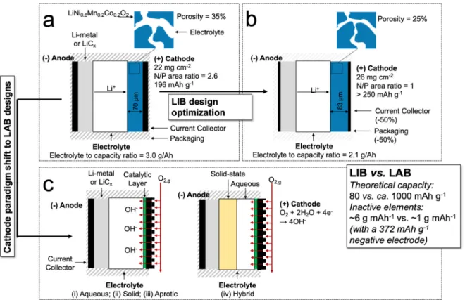
where C is capacity (often mAh g−1), and minactive is the specific mass (g mAh−1) of inactive material (separator, electrolyte, casing, etc.) required to construct the cell. It is evident from Equation (1) that greatly increasing the capacity of one electrode simply associates the cell ca- pacity with that of the limiting electrode. Thus, it is clear that both anode and cathode must be improved for significant increase in overall LIB cell capacity. Over decades, only incremental improvement in LIB electrode capacity has been realized. Liu et al. [69] collected readily achievable parameters for current LIB components, and calculated a specific energy of approximately 350 Wh kg−1 to represent what is typically achieved in LIBs available today. A series of possible im- provements (see Fig. 2(a) & (b)) were considered and increases in ca- pacity were calculated with each additional enhancement.
Each of these steps has associated challenges. It is evident that per- formance parameters of the cathode are central to improving specific energy, but marked advancement in LIB cathode capacity has proven difficult. One strategy to accelerate advancement in battery perfor- mance is the pursuit of new designs with fundamentally different elec- trode configurations (as indicated by Fig. 2(c)), including MAB cells. The MAB cathode material is oxygen itself, which is not a physical compo- nent of the cell. Therefore, the specific capacity of the cathode can be removed in calculating MAB cell capacity, shown in Equation (2) as:
CMAB= 1
1
Canode+minactive (2)
The porous air cathode “skeleton” is estimated [70] to make up less than 10% of the total inactive mass of a MAB system. These character- istics, and high anode metal capacities (Fig. 1(a)), greatly expand the window for MAB capacity enhancement compared to that for LIB sys- tems. This can be illustrated by quantitative examination of LIB capacity
vs. that for an Li-air battery (LAB) cell (see Fig. 2(c)). Using Equation (1), and assuming (i) the hypothetical best cathode capacity case (250 mAh g−1) from Liu et al. [69]; (ii) graphite anode capacity of 372 mAh g−1; and (iii) a specific LIB inactive mass of 6.2 g (Ah)−1 68, LIB capacity is calculated to be near 80 mAh g−1. For the LAB cell, the lithium anode (Fig. 1(a)) has a capacity of 3861 mAh g−1. The LAB inactive mass is on the order [71] of 1 g Ah−1. From Equation (2), LAB capacity is estimated to be near 1000 mAh g−1, at least a 10x increase over the best-case LIB.
This has driven a large body of research to realize the promise in LAB designs. LAB systems can generally be grouped into four types [72–74].
One category employs aqueous electrolytes, as noted by Galbraith in the first report of a LAB system in 1976 [75]. In practice, solubility of LiOH in aqueous electrolytes limits achievable LAB capacities [76], thus making the realization of a LAB cell in aqueous electrolyte challenging.
A second LAB cell type attempts to overcome this with a solid-state hybrid design, in which lithium metal is shielded from moisture, and from atmospheric oxygen and CO2, by a non-volatile solid-state elec- trolyte. This design is a topic of keen study, in which solid electrolyte materials exhibiting chemical, thermal, and mechanical stability should provide high ionic conductivity and simple, low-cost fabrication [72]. A third category is perhaps the most widely studied, utilizing aprotic (non-aqueous) electrolytes. First proposed by Abraham and Jiang in 1996 [77], it introduced feasibility of secondary operation by use of a lithium foil anode, a thin carbon composite anode, and a polymer electrolyte. The idealized cell reaction is:
4Li + O2→2Li2O Eocell = 2.91V (3) Cell discharge was observed to cease when lithium oxide formation caused choking of the oxygen-breathing carbon cathode. Analysis of this discharge product by the authors revealed its actual composition was Li2O2, with cell reaction:
2Li + O2→Li2O2 Eocell = 2.91V (4) The standard cell voltages for the reactions in Equation (3) and
Fig. 2. (a) Illustration of a standard lithium ion battery (LIB) with its main characteristics; (b) characteristics modification undergone to achieve LIB advances through optimization of the current design; (c) illustration of a standard lithium air battery, with an emphasis on the different types of electrolytes to be considered for such designs.
Equation (4) were determined from standard Gibbs free energy of for- mation data for Li2O and Li2O2 [78]. Cycling performance showed that the design was capable of a degree of rechargeability. This cell exhibited an open-circuit voltage of 3.07 V, and employed a cobalt phthalocyanine catalyst in the carbon electrode. The cell was discharged to a capacity of 100 mAh g−1 three times, and recharged to a cutoff voltage of 4.1V and was able to recharge to over 100 mAh g−1 each time. This work was the first of innumerable publications and efforts in the years since to advance aprotic LAB materials and performance. Current topics of research include improvements in electrolyte stability and conductivity [79], maintaining performance in drawing oxygen from atmospheric air containing moisture and CO2 [80], and increasing capacity and dura- bility in recharging [81–83]. The fourth type of LAB looks to solve these issues by implementing a hybrid design in which the lithium anode is in contact with a solid-state electrolyte, and an aqueous electrolyte is used on the air-breathing cathode side of the cell. The power performance of a LAB cell is limited by low diffusion rate of oxygen within the cathode [84], and an alkaline catholyte allows use of ORR catalysts developed for fuel cells [85]. Other advantages include the formation of a soluble discharge product (LiOH, in alkaline electrolytes) [86] rather than insoluble lithium oxides, and safety can be enhanced by avoidance of flammable organic catholytes [87]. The hybrid concept was introduced by Wang and Zhou [88] in 2010, and they later followed up with an interesting variant [89] in which a capacitor electrode was put in con- tact with the non-aqueous electrolyte solution as an additional cathode in parallel with the air-breathing cathode. The objective was to demonstrate that the capacitor cathode could enable peak power output when high power is called for, and the air-breathing cathode would allow good performance in high-energy demand scenarios. They calcu- lated that the peak power capability in a LAB +capacitor battery was nearly ten times higher than that for standard LAB cells.
LAB designs continue to progress, but they have not yet established a firm foothold as products in the commercial market. A metal-air battery that has done so to some extent is the zinc-air battery (ZAB). Although
review of Fig. 1(a) shows that zinc gravimetric capacity and abundance in the earth’s crust are low compared some other metals, its abundance is greater than that for lithium, and the volumetric capacity is second only to aluminum. Zinc also has a prominent place in battery history, being part of the couple (with copper or silver) devised by Volta when he invented his battery in the late 1700’s [90]. Volta created stacks of paired metal discs, and varied the disc materials (tin was also tried), stack heights, and electrolytes (salt solutions or simply water). He evaluated cell performance in part by how strongly the stack could shock him, and even noted how far up his arm the shock could be felt. He observed that cells of silver and zinc, with solutions of neutral or alka- line salts, produced the strongest effects. The first report of a ZAB concept was by Smee in 1840 [91], and Maiche was awarded a French patent for a ZAB design in 1878 [92], in which he modified a Leclanch´e cell [93] by replacing the manganese dioxide cathode with a porous vessel containing platinized carbon. The porous vessel was partially submerged in an electrolyte containing ammonia salt, sodium bisulfite, and sulfuric acid. The carbon material took oxygen from the air and with an anode of zinc amalgam achieved a potential equal to 1.25 V.
Hydrogen generated by reaction of zinc with the electrolyte combined with oxygen in the carbon pores to provide constant depolarization.
Commercial application of this concept began in the 1930’s. G.W. Heise, employed by the National Carbon Company, was issued a patent in 1933 [94] for an air-depolarized primary battery, designed for “sustained,
heavy service”. It comprised the basic components of the Maiche cell, with refinement of carbon and catalyst composition, and substitution of the liquid electrolyte by a solid electrolyte described as “salted paste”
containing ammonium chloride. By 1939, the company had introduced the “Eveready Air Cell” battery [95], for use in telephone transmission service. The Type-600 model was rated at 600 Ah, and contained two cells in series, each cell providing 1.25 V. They were intended to be shipped dry and required addition of ordinary tap water at point of use.
Wax was applied to the carbon cathode to prevent flooding. This basic design endured for decades. The Eveready Air Cell line was active until the 1960’s, and a similar product, known as the Carbonaire battery, was introduced in 1950 by Thomas A. Edison Industries for applications requiring sustained low power, such as railway signal devices and navigation buoys [96].
Primary ZAB’s are probably best known nowadays for their use in hearing aids and heart monitoring devices. Battery-powered hearing aids began to appear in the early 20th century, commonly employing mercury (or mercuric oxide) cells [97]. Pursuits to improve performance and decrease size, along with the desire (later requirement) to eliminate use of mercury due to toxicity, led to the emergence of primary ZAB designs for hearing aids in the 1980’s [98]. The reactions in an alkaline primary ZAB are (SHE =standard hydrogen electrode) [99,100]:
Zn+4OH−→Zn(OH)2−4 +2e− Anode− ZincateIonFormation (5) Zn(OH)2−4 →ZnO+2OH− +H2OAnode− ZincOxidePrecipitation (6) Zn+2OH−→ZnO+H2O+2e− Anode− Overall E◦vs.SHE=-1.25V
(7) 2H2O+2e−→H2+2OH− Parasitic− WaterReduction (8) Zn+2OH− +2H2O→Zn(OH)2−4 +H2Parasitic− ZincCorrosion (9)
The theoretical potential of the primary ZAB cell is 1.65 V, although working voltages are typically near 1.2 V [101]. Several phenomena contribute to departure from ideal performance. Ohmic losses arise from electrical resistance in cell materials, and from resistance of ion trans- port within the electrolyte [102]. Operation in atmospheric air can also lead to CO2 dissolution into the electrolyte. Resulting carbonate for- mation can increase electrolyte viscosity, hindering ionic conductivity [103]. These can be mitigated somewhat by operation in pure oxygen, but this is not practical or economic in most applications. Precipitation of ZnO on the anode surface can induce concentration polarization ef- fects [104]. Activation loss can be seen primarily due to slow ORR ki- netics at the cathode [105]. Materials for ORR kinetics is a topic of keen research, and progress is encouraging. Yan et al. [106] fabricated per- ovskite/carbon nanocomposites as ORR catalysts, and achieved a peak power density in a ZAB cell of 430 mW cm−2, higher than that observed for Pt/C (400 mW cm−2). Discharge data done by Yan et al. also illus- trate a favorable characteristic of primary ZAB cells, first noted by Heise [94] in his patent nearly 90 years earlier, that being the ability to pro- vide steady, low-power performance over their working life. Cell discharge showed little voltage decay over 170 h at a current density of 10 mA cm−2, and 21 h at 100 mA cm−2.
Although zinc is more abundant than lithium (see Fig. 1(a)), and can be recycled [107], considerable recent effort has been put into 1
2O2+H2O+2e−→2OH− Cathode− Oxygem Reduction ReactionE◦vs.SHE= 0.4V (10)
development to realize a high-performing, rechargeable ZAB design.
Zinc has a low equilibrium potential, and this, combined with a high overpotential for the hydrogen evolution reaction (HER), makes it the most active metal that can be electrodeposited from aqueous solutions [108,109]. Some effort has been put into use of acidic aqueous elec- trolytes, though air cathode catalyst activity can suffer [110]. Neutral aqueous electrolytes have some favorable attributes, including very low CO2 uptake to minimize carbonate effects, and low zinc solubility, which may help to suppress dendrite growth [111]. Stability of pH at electro- de/electrolyte interfaces is among the topics of research, as locally acidic conditions at the cathode can likewise interfere with air catalyst function and stability [112]. Alkaline solutions have garnered the most attention among aqueous electrolytes, with attractive features including high ionic conductivity of the electrolyte, favorable conditions for cathode operation, and high solubility of zinc salts [113,114]. Among hindrances requiring mitigation are carbonate formation within the electrolyte [115], redistribution of zinc over charge/discharge cycling, resulting in electrode morphology changes that can reduce active sur- face area [100], and uneven zinc deposition during charge cycles, causing dendrite formation that can lead to short-circuiting [116]. These issues, along with hydrogen evolution and aqueous electrolyte water evaporation effects, have led researchers to also pursue non-aqueous electrolytes for secondary ZAB systems. For safety and performance, non-aqueous electrolytes (e.g. aprotic solvents, ionic liquids) should not be volatile, have low toxicity, and provide high ionic conductivity. This topic of study is still in relatively early days, but some positive results indicate that it may ultimately bear fruit. Guerfi et al. [117] evaluated a secondary ZAB cell comprising a polyaniline emeraldine as cathode, zinc metal as anode, and an electrolyte consisting of 0.3 M zinc-bis (trifluoromethyl-sulfonyl) imide Zn (TFSI)2 dissolved in propylene car- bonate. Dissolution of the zinc anode led to significant self-discharge, but the battery showed an output capacity of 148 mAh g−1 at 1C rate (full discharge in 1 h), with a columbic efficiency of 99.5% over 2000 cycles between 0.4 V and 1.4 V. As noted generally by Masa et al. [118]
for electrocatalysis, published works tend to report experimental con- ditions not necessarily representative of that expected in operating en- vironments. For secondary ZAB development in particular, Zhang et al.
[119] recommend that charge/discharge cycles be carried out at a current density of at least 10–20 mA cm−2, with charge/discharge pe- riods of greater than 1 h (corresponding to an areal capacity of at least 10 mA cm−2) for a minimum of 10 cycles to effectively evaluate real cycling performance.
LAB and ZAB cells each offer promise and face challenges. As noted by Lee et al. [120], ZAB cell components are moisture-tolerant, and presumably could be manufactured in ambient air conditions. Zinc is inexpensive and recyclable. LAB cells would require inert atmosphere manufacture but may show better cycling performance at higher oper- ating potentials. A third MAB alternative is the AAB cell, the topic of the remainder of this manuscript. Aluminum retains the safety and economy of zinc, with higher volumetric capacity (Fig. 1(a)), and a cell standard potential nearly equal to that for LAB cells. Aluminum reactions in aqueous alkaline electrolyte (pH =14) have been described [121–123]
as:
Al+3OH−→Al(OH)3+3e− Anode− HydroxideFilmFormation (11) Al(OH)3+OH−→Al(OH)−4 Anode− HydroxideFilmDissolution (12) Al+4OH−→Al(OH)−4+3e− Anode− OverallE◦vs.SHE = -2.35V
(13) O2+2H2O+4e−→4OH− CathodeE◦vs.SHE = 0.39V (14) 3H2O+3e−→3OH− +3
2H2Water ReductionE◦vs.SHE = -0.84V (15)
Al+3 4O2+3
2H2O+OH−→Al(OH)−4 AnodicDissolution (16) Al+3H2O+OH−→Al(OH)−4 +3
2H2Corrosion (17)
A hydroxide film is electrochemically formed via Equation (11).
Hydroxide ions migrate towards the aluminum/film interface, with disruption of the passive oxide layer. The hydroxide film itself is attacked chemically by OH−, as shown in Equation (12). Combining Equations (11) and (12) yields Equation (13), the partial anodic disso- lution reaction of aluminum. Electrons produced in Equation (13) can be consumed by either Equation (14), the ORR occurring at the cathode, or by water reduction (Equation (15) that results from severe losses in voltage when different areas within the Al electrode act as both cathodic and anodic sites [124]. Adding Equation (14) to Equation (13) provides Equation (16), the overall reaction for AAB anodic dissolution.
Combining Equation (15) with Equation (13) gives Equation (17), an aluminum corrosion reaction with hydrogen evolution. Corrosion in aqueous electrolytes is a barrier to development and commercialization of AAB systems, thus non-aqueous electrolytes are being pursued as an alternative., the most notable one being the use of ionic liquids. How- ever, the reactions in these electrolytes are chemistry-dependent, and not generally known with precision. Broadly, the overall reaction of an AAB in non-aqueous electrolytes is postulated [125] as:
4Al +3O2 → 2Al2O3 (Overall) (18) A second attractive aspect of employing ionic liquid electrolytes is enabling rechargeability not possible in aqueous systems. Evolution of hydrogen will thermodynamically occur before aluminum deposition due to the high negative standard potential of aluminum. This is clearly depicted in a view of the Al-water Pourbaix diagram [126], discussed in a following section of this work.
A considerable body of literature exists for design and performance of air-breathing cathodes and ORR catalysts for AAB applications, and elsewhere for other MAB designs and fuel cells. This topic has been extensively evaluated, and only several published works [58,127–136]
and a brief synopsis are provided here. AAB cathode performance is a key AAB design parameter, as slow ORR kinetics contribute to limita- tions in cell specific energy and specific power [38]. Atmospheric air contains CO2, which can lead to formation of insoluble carbonates [137]
and reduced cathode performance in alkaline solutions. The ORR described by Equation (14) is a “4-electron reduction”. In practice, ORR mechanisms are not fully elucidated, but the direct 4-electron path in- volves numerous intermediate species, such as adsorbed O, OH, O−2 or HO−2 and often compete [138] with a 2 ×2 or 2e− electron process, the latter leading to H2O2 formation [139], this depending upon catalyst type and electrolyte chemistry. Many catalysts have been evaluated for alkaline AAB cells, with much effort in replacing platinum group metals due to cost and availability constraints. Sun et al. [140] studied silver-doped manganese oxide as an AAB ORR catalyst. MnOx alone had previously demonstrated [141] poor electrical conductivity, hindering fast electron transfer and discharge rate. Optimal silver content in Ag–MnO2/C was found to be 17% (by weight), with the addition of silver providing a three-fold increase in specific surface area. Stability was demonstrated by 97.5% current retention after running for 45 000 s.
Operation in an alkaline AAB cell resulted in a peak power density of 315 mW cm−2, compared to 261 mW cm−2 for MnO2/C. Bismuth oxy- chloride (BiOCl) was examined by Yuan et al. [142] as AAB ORR cata- lyst. A 2-electron reaction pathway was suggested by analysis of ORR polarization curves and Koutecky-Levich [143,144] plots. The catalyst was in the form of BiOCl micro-assemblies consisting of ultrafine nanoplates, and achieved a current density of about 550 mA cm−2 at 0.5 V (vs. SHE), compared to ~450 mA cm−2 at the same potential for a cell using a MnO2/C cathode catalyst. The BiOCl/C cathode (4 wt%) was coupled with an aluminum anode in an alkaline AAB cell to obtain
discharge performance at current densities of 50-, 100-, and 200 mA cm−2. Cell potential in each case was higher for BiOCl/C as air cathode catalyst compared to MnO2/C, with a high of 1.47 V after 3000 s at 50 mA cm−2 current density. Nitrogen and cobalt were co-doped by Liu et al. [145] onto a porous carbon material as AAB ORR catalyst. This catalyst (dubbed NCAC-Co) achieved a half-wave potential [146] (0.74 V vs. RHE) nearing that of 20% platinum on carbon (0.79 V vs. RHE), and a 4-electron reaction pathway was estimated by linear sweep vol- tammetry measurements and Koutecky-Levich plots. AAB cells employing NCAC-Co/C and Pt/C cathodes (as control) were assembled and operated in 6 M KOH. The cell with a NCAC-Co-/C cathode achieved a power density of 54.6 mW cm−2 at 0.7 V (vs. RHE), comparable to that (54.6 mW cm−2) for a cell under the same potential with a 10% Pt/C cathode, but lower than achieved (56.7 mW cm−2) with a 20% Pt/C cathode. Catalyst stability was observed by galvanostatic discharge for 5000 s at a current density of 200 mA cm−2. Voltage decrease was 0.17, 0.21, and 0.20 V for cells with NCAC-Co, 10% Pt, and 20% Pt, respec- tively, indicating relative stability of NCAC-Co to platinum. A study [147] by Jin et al. used Pt/C cathodes to consider the effect on ORR of alkaline electrolyte composition. A series of NaOH and KOH aqueous solutions ranging from 0.5 M to 14 M concentration were subjected to cyclic voltammetry scans. Peak potential shifted monotonically in the negative direction for both electrolyte types, with significant decrease in current density, indicating that the ORR is impaired with increasing electrolyte concentration. KOH peak potential was more positive than that for NaOH at all concentrations, with higher current density, sug- gesting higher ORR performance in KOH relative to NaOH. A 2-electron reaction mechanism was seen at low concentrations, but a shift to a 1-electron transfer pathway was observed at concentrations above 4 M for both electrolytes. This was explained by reduced protonation of O−2 by water to produce the HO−2 intermediate, given higher concentration of OH− in strong alkaline electrolytes.
Air-breathing cathodes in rechargeable batteries require a bifunc- tional catalyst. The oxygen evolution reaction (OER) occurs at the cathode during recharging, in which oxygen is generated from OH−, with intermediates including MOH, MO MOOH, and MOO−, where M is the metal in the OER catalyst. The binding energies for the ORR and OER reaction mechanism intermediates [148] are dissimilar, and so catalysts optimized for either ORR or OER are generally not suited for the other [149]. Gao and Qin [150] considered carbon microspheres (CM) as bifunctional catalyst for non-aqueous rechargeable Al–O2 batteries. The battery cell utilized an ionic liquid electrolyte formed from a 1.3:1 mixture of AlCl3 and 1-ethyl-3-methyllimidazolium chloride, and an aluminum metal anode. CM catalyst diameter was 300–400 nm, with a specific surface area near 600 m2 g−1. Cycling performance was observed at current densities from 25 mA cm−2 to 100 mA cm−2. Cathodic polarization increased with increasing current density, though a capacity near 250 mAh g−1 was reached at 100 mA cm−2. Stable discharge capacity near 200 mA g−1 was achieved over 35 cycles at 50 mA cm−2 current density. Scanning electron microscopy showed that subsequent capacity degradation after further cycling was caused by CM decomposition that led to pore clogging. Improvement of CM catalyst performance was attempted in a later study [151] by CM doping with boron, coupled with the same electrolyte and Al anode. Cycling stability with boron doping was not notably improved, but reduced cathodic overpotential and higher discharge capacity (300 mAh g−1), were seen, compared to undoped CM catalyst at 50 mA cm−2 current density. This was linked to increased surface area (~800 m2 g−1) in boron-doped CM microstructures, induced by boron etching defects on the CM surface.
Cobalt ion intercalated manganese oxide (Co–MnO2/C) was evaluated by Xia et al. [152] as air cathode catalyst in a rechargeable AAB CR2032 button cell, coupled with an aluminum anode and a 1.3:1 mixture of AlCl3 and urea as an ionic liquid electrolyte. Catalysts with cobalt ion additions from 10% to 50% (mole percent of Co to Mn) were tested.
Specific surface areas and pore sizes were calculated by the Brunauer-Emmett-Teller method. It was found that Co ion addition
increased surface area by roughly five-to-six-fold, with 40% Co showing the highest specific area (153.81 m2 g−1, vs. 23.56 m2 g−1 for undoped MnO2/C), and average pore diameter was reduced by an order of magnitude (72 nm for 40% Co, vs. 6.62 nm in undoped MnO2/C). Large pore depressions on the surface of the 50% Co sample were said to be the cause of slightly reduced specific surface area compared to the 40% Co sample. A peak at the binding energy of 781.8 eV, determined by x-ray photoelectron spectroscopy, indicated the presence of some Co2+ion, but the splitting value of binding energies for Co2p1/2 (795 eV) and Co2p3/2 (780 eV) suggested that Co primarily existed as Co3+. OER ki- netics are known to be enhanced by Co3+catalytic effects [153,154].
Charge/discharge cycles were conducted on the AAB cell for nearly 90 h at a capacity of 375 mAh g−1. Discharge voltage remained above 1 V, and charging voltage did not exceed 2.5 V. The authors attributed per- formance degradation over time to three factors. Firstly, oxygen diffu- sion and electron transport were hindered by accumulation of discharge products at the air cathode. Gradual decomposition of the electrolyte was a second cause. Finally, catalyst poisoning over time leads to reduced electrocatalytic activity. These studies are among those demonstrating feasibility of bifunctional catalysts, and the tangible, if incremental, progress being steadily made in realizing highly functional and durable cathode materials for both primary and rechargeable AAB cells.
3. Alkaline electrolyte chemistry with pure aluminum
Among aqueous electrolytes, alkaline solutions are most commonly considered due to higher theoretical cell potential [126] and higher achievable power [155] than neutral or acidic solutions. However, aluminum suffers high corrosion rates in alkaline media at open circuit potentials [124], and hydrogen will be produced at more positive po- tentials than for aluminum metal formation from aluminum ions in so- lution (showing rechargeability in aqueous systems to be infeasible).
Passivating oxide or hydroxide surface layers will form, resulting in high overpotentials for anodic dissolution [156]. These are illustrated in Fig. 3(a), using a Pourbaix diagram constructed using Pourbaix’s typical conventions [157], and the behavior of aluminum is acid, neutral, and alkaline electrolytes. The Pourbaix diagram depicts the tendency for reduced Al immunity in alkaline electrolytes compared to acidic or neutral solutions. Callouts in Fig. 3(a) also show the following: (i) favorability of Al3+ions to exist in acid media, via reactions of protons with the boehmite (γ-ALOOH) surface layer; (ii) the passive nature of the alumina film in neutral solutions; and (iii) the favorability of Al(OH)−4 ions produced by reaction of OH− with the Al(OH)3 surface layer that is present in alkaline solutions. Interestingly, Fig. 3(b) shows greater corrosion rate in neutral electrolyte compared to acidic, as a function of current density. Moon and Pyun [158] reported that a proton is dis- charged in acidic solutions under cathodic potential, and the impact of this proton discharge in acidic solutions is minimal. This is manifested by the relatively flat corrosion rate curve for acidic solution in Fig. 3(b).
Water reduction described by Equation (15) occurs in neutral and alkaline solution under cathodic polarization. Thus, a gradual increase in hydroxide ions via water reduction is responsible for the increase in corrosion with increasing cathodic polarization in the neutral solution.
Hydroxide ion concentration is already high in the alkaline solution, resulting in the near-constant corrosion rate in alkaline solution, irre- spective of applied current density. Fig. 3(c) shows that a more negative open-circuit potential is achieved in alkaline solution than in acidic or neutral solutions. This introduces the concept of “activation” in which the aluminum surface becomes more electrochemically active as the passive oxide layer is disrupted. Moon and Pyun [158] utilized an electrode that enabled abrasion of the aluminum to maintain a bare metal surface. The increase in open-circuit potential with time for all solutions in Fig. 3(c) indicates that reformation of oxide or hydroxide films does occur to a degree in the absence of mechanical disruption.
Pure aluminum is most anodically active in alkaline electrolyte, but
corrosion is severe. Fig. 3(b) indicates a factor of 25 increase in corrosion in alkaline over acid and neutral at 10−2 mA cm−2 cathodic current density).
Brown and Whitley [159] examined the electrochemical behavior of 99.999% pure aluminum in room temperature KOH solutions in several concentrations from 0.1 M to 4 M and observed a pH dependence be- tween the HER on aluminum and the OH− concentration. Furthermore, the absence of linear regions in the Tafel plots and the current stabili- zation at high overpotentials are indicative of Al dissolution through the passivation film, underlining the easy-to-corrode nature of aluminum.
Other works have postulated a role for aluminum hydrides in aluminum dissolution, particularly AlH3 in alkaline electrolytes. Perrault [160]
observed that aluminum open circuit potential in strongly alkaline so- lutions aligns closely to the Nernst potential for aluminum hydride oxidation to aluminate ions, implying the possibility of aluminum hy- dride on the aluminum surface acting as a dissolution reaction inter- mediate. Despi´c and others [161,162] also furnished evidence of aluminum hydride formation and its presence was directly evidenced by Adhikari [163] using secondary ion mass spectroscopy. It is assumed that the presence of H-vacancies in the AlH3 structure, and the resulting nano-scale voids, are acting as starting points for pitting corrosion of the aluminum.
To achieve a better understanding of the hydroxide layer, Doche et al. [164] studied the electrochemical behavior of 99.999% aluminum in 4 M NaOH. They and others [165–167] proposed that Equation (12) occurs as three single-step electron transfers via hydroxide addition to form solid Al(OH)3, followed by further hydroxide addition to produce Al(OH)−4, as described in Fig. 2(b). The hydrogen evolution reaction (HER) occurs simultaneously on the aluminum surface, creating competition between adsorbed hydrogen atoms and intermediate oxidation products. This mechanism is useful in explaining transient behavior observed upon immersion of aluminum into the electrolyte.
First, the air-formed aluminum oxide layer quickly dissolves (Al2O3 → Al(OH)−4). A mixed potential of ca. − 1.63V vs. SHE is initially observed.
The bare aluminum surface then undergoes rapid dissolution, forming
hydroxide (Al → Al(OH)3), with simultaneous HER. The transient behavior ends with a decrease of the oxide layer dissolution rate, the stabilization of the Al(OH)3 layer and the shift of the mixed potential to
− 1.66 V vs. SHE. In general, the combination of (i) the for- mation/dissolution of passivating layers (Al2O3) and discharge product layers (Al(OH)3); (ii) Al corrosion; and (iii) HER lead to cell voltages in the 1.2–1.6V range [58], significantly lower than the theoretical value of 2.35V [168]. Efforts to improve on the performance of pure aluminum have led to consideration of alloying metals to activate the anode surface while minimizing corrosion.
4. Alkaline electrolyte chemistry with aluminum alloys
Desired properties of alloying metals include [55,169,170] a lower melting point than aluminum, the ability to form a solid solution with aluminum, higher nobility than aluminum, high hydrogen Fig. 3.(a) Pourbaix diagram for the aluminum-water system; (b) corrosion rates of pure aluminum as a function of applied cathodic current density at 20 ◦C in various aqueous solutions (inspired from Ref. [158]); (c) open circuit potential transients obtained after interrupting abrading action on pure aluminum specimen at 20 ◦C in de-aerated aqueous solutions (inspired from Ref. [158]).
Table 1
Property data for aluminum, gallium, indium, and tin. (s) single bond, (d) double bond.
Aluminum Gallium Indium Tin Melting Point, (◦C) 660.4 29.8 156.6 232.0
E◦vs. SHE (V) −1.66 −0.53 −0.34 −0.14
HER onset potential vs.
SHE (V)
−0.47 −0.68 −0.80 −1.00
Solubility in Al (wt. %) – 20.4 0.19 0.12
Metal-Hydrogen Bond
Energy (kJ mol−1) 285 276 247 255
Metal Group IIIA IIIA IIIA IVA
Atomic Radius (Å) 1.431 1.221 1.626 1.405
Ionic Radius (Å) 0.50 0.62 0.81, 1.32 0.71, 1.02 Covalent Radius (Å) 1.25 1.25 1.50 1.40(s), 1.30 Electronic Configuration [Ne] (d)
3s23p1 [Ar]
3d104s24p1 [Kr]
4d105s25p1 [Kr]
4d105s25p2 Usual Oxidation State +3 +3 +3, +1 +4, +2
overpotential, and solubility in alkaline electrolytes. The group of alloying metals considered in the Pryor patents [22–29] and elsewhere [171–174] is extensive, however this manuscript surveys work on the three elements most commonly studied – Sn, In, and Ga. Property data [175–182] for these metals and aluminum are given in Table 1.
A melting temperature below that of aluminum eases diffusion of the alloying element into the solid aluminum structure during the formation of solid solutions. As reported by Reboul et al. [183] and others [56,165, 184,185], metals nobler than aluminum activate the aluminum in a 3-step surface segregation process, as follows:
1. Dissolution of aluminum caused by the galvanic couple,
2. Oxidation of aluminum and the alloying element(s), releasing cat- ions into the electrolyte, i.e. Al(M) → xAl3++Mn++ye− (x and y are dependent of the solid solution composition,
3. Plating of cathodic cations produced in Step (1) back onto the anode surface, promoting further anodic dissolution of aluminum by impairing the stability of the passive oxide layer (Al +Mn+→ Al3++ M).
Surface segregation of the more noble alloying element(s) also sup- presses aluminum corrosion to a degree due to their higher HER
overpotentials. Rüetschi and Delahay [178] correlated hydrogen over- potential to the strength of the metal-atomic hydrogen bond for a number of metals. They showed a linear increase in overpotential with decreasing bond strength. Table 1 shows agreement with this for the Group IIIA metals. Tin, a Group IVA metal with an additional valence electron, does not follow the trend. The beneficial effects of alloying elements to anodic dissolution of aluminum are generally seen when only solid solutions are present in the alloy. Concentrations exceeding solubility limits lead to precipitate phases of the alloying element and adverse effects upon self-corrosion [22,56,172,183,186]. This will be discussed further in the following sections on specific effects of Ga, In, and Sn additions to aluminum. Reding and Newport [187] evaluated the effects of over 2500 alloying elements on aluminum anodes for cathodic protection in seawater environments. Gallium, indium, and tin were among the elements identified to create Al-alloys that are more active than pure aluminum. Several subsequent studies of binary Al–Ga/Al–In/Al–Sn alloys in alkaline electrolytes will be discussed here, with corrosion current density (Table 2) as a common parameter for comparison.
Table 2
Published corrosion data at open circuit potential for binary Al alloys of gallium, indium, and tin. The ideal gas law and Faraday’s laws of electrolysis were combined as necessary to relate hydrogen evolution to corrosion current density [55,188,189].
Alloy Composition
(wt. %) H2 evolution rate, (mL min−1 cm−2) Corrosion rate,
(mg min−1 cm−2) icorr (mA cm−2) Open circuit potential vs. SHE (V)
Al–Ga, Tuck et al. [190] 0.1% Ga 1.7 74
0.26% Ga 4.7 206
2.6% Ga 8.0 351
Al–Ga, Macdonald et al. [191] 0.01% Ga 11.948 8.740 63 −1.69
0.05% Ga 8.110 5.707 41 −1.72
0.1% Ga 8.217 5.845 42 −1.70
0.5% Ga 9.856 7.627 55 −1.71
99.99% Al 0.726 0.515 55 −1.58
Al–Ga, Hunter [192] 0.013% Ga 3.9 3.1 550 −1.68
0.026% Ga 12.1 9.7 1700 −1.75
0.055% Ga 14.3 11.4 2000 −1.76
0.10% Ga 36.6 29.2 5200 −1.75
0.24% Ga 24.3 19.4 3500 −1.79
2.3% Ga 58.9 47.1 8400 −1.79
Al–In, Macdonald et al. [191] 0.01% In 2.799 1.910 14 −1.60
0.05% In 3.330 2.287 16 −1.62
0.1% in 2.894 1.965 14 −1.64
0.5% In 3.046 2.106 15 −1.64
Al–In, Hunter [192] 0.02% In 0.29 0.23 41.17
0.037% In 0.13 0.1 18.5
0.074% In 0.04 0.03 5.37
0.16% In 0.1 0.08 14.92
0.21% In 0.62 0.49 88.31
0.42% In 0.03 0.026 4.77
Al–In, Scamans et al. [193] 0.038% In 0.007 0.050 −1.65
0.074% In 0.009 0.064 −1.65
0.083% In 0.005 0.036 −1.68
0.11% In 0.005 0.036 −1.62
0.2% In 0.004 0.029 −1.71
Al–Sn, Lee and Kim [194] 0.04% Sn 0.37 40 −1.62
0.09% Sn 0.26 34 −1.60
0.12% Sn 0.2 26 −1.61
0.2% Sn 0.3 39 −1.62
0.4% Sn 0.32 42 −1.63
Al–Sn, Hunter [192] 0.022% Sn 5.76 822.8 41.17
0.044% Sn 0.61 87.1 18.5
0.089% Sn 0.46 66.2 5.37
0.12% Sn 0.27 39.38 14.92
0.23% Sn 0.14 20.29 88.31
0.4% Sn 0.18 25.06 4.77
Al–Sn, Scamans et al. [193] 0.05% Sn 0.05 0.36 −1.53
0.08% Sn 0.03 0.21 −1.59
0.25% Sn 0.03 0.21 −1.59
0.45% Sn 0.03 0.21 −1.59
4.1. Aluminum–gallium alloys
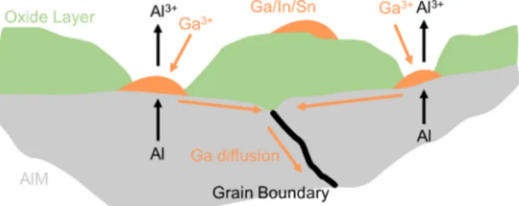
According to Tuck et al. [190], the activation of an Al–Ga anode can occur as a result of several electrochemical/morphological factors. In the case of low levels of Ga, it occurs after polarization below the Ga/ GaO33 − reduction voltage (− 1.55 V vs. SHE), which suggests that acti- vation is caused by of reduction of gallium ions present in their oxide films to form active gallium sites. Surface agglomeration at higher levels of Ga content also initiated activation. In both instances, Ga metal on the alloy surface disrupted the Al2O3 oxide layer by cracking and thinning the layer to enhance Al diffusion and dissolution. By opposition, when formation of surface gallium was impeded, by back-diffusion of gallium into the aluminum matrix, or by slowing Ga mobility by cooling below the gallium melting point, activation was inhibited. The authors concluded that a critical level of gallium surface coverage existed, below which the alloy would not activate. This critical level was determined to be 3 μg cm−2 in 4 M NaOH at 60 ◦C, which corresponds to Ga content
>0.1 wt % in the alloy. Gallium content in the alloy below this threshold did not allow for surface gallium concentrations to disrupt the oxide layer and thus enable aluminum diffusion and activation. Al–Ga alloys were included in a corrosion study at 50 ◦C in 4 M KOH by Macdonald et al. [191] for evaluation of AAB anodes. The addition of gallium to aluminum shifted the open circuit potential by 120 mV in the cathodic direction, with a 20-fold increase in corrosion rate compared to pure aluminum. Corrosion rate increased with time, due to the surface roughening in alkaline environment. Effect of mechanical history of 0.5 wt % Ga–Al alloys on corrosion rate was examined by degree of
“cold-working”, defined by the amount of pressing and rolling of alloy
material before subjecting it to electrochemical testing. No obvious correlation of cold-working to corrosion rate was observed. Annealing at 380 ◦C for 2.5 h produced higher corrosion rates than for any cold-worked sample. The observed high corrosion rates in all considered cases suggested that binary Al–Ga alloys would not be suitable as AAB anodes (see Table 2). According to Hunter [192] (see Table 2 for reac- tivity details), Al–Ga (here prepared by heat-treatment at 600 ◦C of cast bars followed by water quench) acts as a superactive alloy when Ga >
0.26 at. %. Hunter described aluminum activation as having several levels: (i) unalloyed aluminum undergoing corrosion in alkaline elec- trolytes is the active state; (ii) an aluminum alloy with a lower open circuit potential and a higher activity is defined as superactive; (iii) an aluminum alloy with an even lower open circuit potential and extremely high corrosion rates is defined as hyperactive. For Hunter’s hyperactive alloys, pitting corrosion was observed, with discrete Ga-rich phases appearing on these surfaces [192]. Aluminum dissolution was charac- terized by grain boundary attack and disintegration of the aluminum surface. Other researchers have obtained single data point information for open circuit corrosion current densities of Al–Ga alloys in alkaline solutions: Choi et al. [195] measured a corrosion current of 91.25 mA cm−2 for a 0.47 wt % Ga alloy in 4 M NaOH, vs. 22 mA cm−2 for pure aluminum tested under the same conditions. The alloy had been annealed at 450 ◦C for 2 h and water-quenched. The severe corrosion observed was attributed to gallium surface particles promoting aluminum oxide dissolution. Fig. 4(a) is a collection of the corrosion current densities discussed in this section. Data are widely dispersed, but the aggregate of works indicates that Al–Ga binary alloys are unsuitable for use as AAB anodes, and that corrosion rates tend to increase with
Fig. 4.(a) Corrosion current density as a function of gallium concentration in binary Al–Ga alloys [190–192,195]; (b) Corrosion current density as a function of indium concentration in binary Al–In alloys [169,191–193,196,197]; (c) Corrosion current density as a function of tin concentration in binary Al–Sn alloys [192,194, 198]; (d) Polarization curves comparing performance of pure aluminum with 200 ppm Ga, In, and Sn binary alloys in 4 M NaOH at 60 ◦C [193].
increasing gallium content via the mechanisms described.
4.2. Aluminum–indium alloys
In their study of Al–In alloys at 50 ◦C in 4 M KOH, Macdonald et al.
[191] found that corrosion was much reduced compared to Al–Ga alloys, but still higher than that for pure aluminum. Open circuit potentials were shifted approximately 50 mV in the cathodic direction relative to pure aluminum, and observed corrosion rates were greater than aluminum by a factor of 4–5, with a minimal variation of the corrosion rate when varying the In content from 0.01 wt % In to 0.5 wt % In (Table 2). The authors suggested that minimum critical concentrations exist for inhibition of corrosion by some alloying elements, including indium, and that the inhibitive effects were saturated at the concen- tration levels used in their work. Similarly, Hunter’s [192] evaluation of Al–In alloys did not reveal an obvious correlation of galvanostatic corrosion current density to indium concentration under open circuit conditions (Table 2). It was speculated that specimen treatment prior to testing may have contributed to the somewhat random nature of the results, as the surfaces characterized were prepared in a similar fashion to the Al–Ga samples, but not ground nor polished prior to the experi- ment. Scamans et al. [193] also studied Al–In alloy behavior in 4 M NaOH (Table 2), finding, in opposition to Hunter [192] and Macdonald et al. [191], extremely low corrosion currents for Al–In alloys. This implies a potential effect of the material preparation (although not clearly stated by Scamans et al. [193]) prior to testing on its reactivity.
Several other researchers have obtained single data point information for open circuit corrosion of Al–In alloys in alkaline solutions. Wil- helmsen et al. [169] reported a corrosion current density of 5.3 mA cm−2 in 4 M KOH at 60 ◦C for an alloy with 0.1 wt % In content in aluminum vs. 87 mA cm−2 for pure aluminum, i.e. a much lower value than observed by Macdonald et al. [191] and Hunter [192]. This might result from the time length (18–20 h) over which the corrosion rate was established, vs. ca. 1 h for other works. Interestingly, they observed the highest corrosion during the first hour of exposure of the Al–In alloy to the electrolyte. El Abedin and Saleh [196] exposed an alloy with 0.77 wt
% In content in aluminum to 4 M KOH at room temperature for 30 min and reported aluminum tested in identical conditions. Here, the alloy melt was cooled in air, and samples for corrosion testing were used in the cast state. Sun and Lu [197] used vacuum melting and drop casting to prepare an alloy with 0.5 wt % In content in Al. Samples were annealed at 580 ◦C for 2 h and water-quenched prior to testing. The specimens were exposed to 4 M NaOH at 25 ◦C for 1 h, and evolved hydrogen was collected to determine corrosion rate. Corrosion current density for the alloy was reported as 7.06 mA cm−2 vs. 13.8 mA cm−2 for pure aluminum. Fig. 4(b) is a collection of the Al–In corrosion current den- sities discussed in this section. Aside from one data point collected by Hunter [192], corrosion rate appears to somewhat static with increasing In content above the solubility of indium in aluminum (0.19%, Table 1), in agreement with the saturation concept raised by Macdonald et al.
[191]. The collective works suggest that alloy preparation plays a key role in anode performance, in addition to composition. This will influ- ence manufacturing processes developed for any Al alloy anodes if they are ultimately successful in penetrating commercial markets.
4.3. Aluminum–tin alloys
Lee and Kim [194,198] examined Al–Sn alloys exposed to 4 M NaOH (Table 2). Alloy materials were melted under inert atmosphere in an induction furnace and poured into graphite molds. Surface graphite was removed by milling. The alloys were then annealed at 600 ◦C for 2 h, and water-quenched. Pure aluminum exhibited an anodic polarization curve with reasonably constant slope, while the Al–Sn alloys displayed more complex behavior. The authors defined 4 regions of electrochemical behavior for Al–Sn alloys, as follows:
− Activation of the alloys was observed for potentials between − 2.2V and − 1.8V vs. SHE.
− Current output increased with a secondary activation between
− 1.4V vs. SHE and − 1.1V vs. SHE.
− Strong current oscillations were seen from − 1.1V vs. SHE to − 1.0V vs. SHE.
− Current density fell rapidly at potentials from − 1.0 V vs. SHE to
− 0.6V vs. SHE, with polarization behavior similar to that of pure aluminum, indicating that tin did not activate aluminum in this region.
Lee and Kim noted that regions of aluminum-tin activation aligned with those of stability of tin metal (Fig. 5), indicating that surface tin deposits drove the activating behavior relative to aluminum. The decreased anodic dissolution observed at higher potentials was believed to arise from the tin dissolution (Sn → SnO32−) in the electrolyte.
Hunter [192] investigated a series of Al–Sn alloys in 4 M NaOH (Table 2). As with other alloys in his work, they were prepared by chill-casting, followed by annealing at 600 ◦C and water quenching. It was found that 1–2 h of annealing at 600 ◦C were sufficient to form solid solutions of tin in aluminum, but that longer annealing times under these conditions produced discrete tin particles along grain boundaries, defined in the study as an “inverse solubility” effect. Similar to Lee and Kim [194,198], Hunter’s work correlated aluminum activation to re- gions in which tin metal is stable. He found that a minimum tin content of 0.01% was necessary to observe activated aluminum behavior. Sca- mans et al. [193] also investigated Al–Sn alloy behavior in 4 M NaOH, prepared similarly to their Al–In alloys. It was found that corrosion performance was relatively independent of tin level, although much lower than observed by Hunter, Lee, and Kim, again suggesting signif- icant impact of the preparation process on the alloy activation behavior.
The comparison of Al–Sn corrosion current densities is presented in Fig. 4(c). As with indium, the beneficial effects of aluminum activation as a function of tin content appear to somewhat plateau beyond the solid solubility limit. For tin concentrations exceeding solubility, little evi- dence of enhanced corrosion induced by tin as a second-phase precipi- tate is observed.
Scamans et al. [193] included a polarization study in their work, reproduced in Fig. 4(d), describing the behavior of Al–Ga/Al–In/Al–Sn alloys containing 200 atomic ppm of the alloying constituent, and for 99.99% aluminum. All alloys exhibited more negative potentials compared to aluminum alone at current densities greater than 100 mA cm−2. They used a reaction microcell (also used by Hunter [192]) with a
Fig. 5.Polarization curves for pure aluminum and Al-0.04 wt% Sn alloy in 4 M NaOH at 60 ◦C with electrode potential [198].

![Fig. 4. (a) Corrosion current density as a function of gallium concentration in binary Al – Ga alloys [190 – 192,195]; (b) Corrosion current density as a function of indium concentration in binary Al–In alloys [169,191–193,196,197]; (c) Corrosion current](https://thumb-ap.123doks.com/thumbv2/123dok/11949207.0/9.892.119.768.555.1062/corrosion-current-function-concentration-corrosion-function-concentration-corrosion.webp)
![Fig. 5. Polarization curves for pure aluminum and Al-0.04 wt% Sn alloy in 4 M NaOH at 60 ◦ C with electrode potential [198]](https://thumb-ap.123doks.com/thumbv2/123dok/11949207.0/10.892.466.828.778.1070/fig-polarization-curves-aluminum-alloy-naoh-electrode-potential.webp)