.
Rev 07A NA C OM
Standard C
Intelsat Extended — EC INSAT — XC
Russian — RC PALAPA — PC
ANASAT ® -C Series C-Band Transceiver
Operating Manual
A NA C OM
Standard C
Intelsat Extended—EC INSAT—XC
Russian —RC PALAPA—PC
ANASAT ® -C Series C-Band Transceiver
Operating Manual
The information furnished by AnaCom, Incorporated, in this publication is believed to be accurate and reliable.
However, no responsibility is assumed by AnaCom for its use, nor any infringements of patents or other rights of third parties resulting from its use. No license is granted by implication or otherwise under any patent or patent right of AnaCom, Inc. AnaCom reserves the right to change circuitry and specifications at any time without prior notice.
The following terms are trademarks of their respective holders:
AnaSat AnaCom, Inc.
Polyswitch Teflon Duroid
VT52, VT100 Digital Equipment Corp.
INTELSAT
A NA C OM Inc.
1506 Dell Avenue Campbell CA 95008
Tel: (408) 379-7482 Fax: (408) 379-7483
You have just received a AnaSat
®-C Transceiver, a cost-effective product with no compromise on quality and reliability. This product should provide tireless performance in any reasonable operating environment.
We, at A
NAC
OM, have taken great care to provide a convenient, easy-to-use product in a single package. Our powerful Monitor and Control enables you to set transmit and receive frequencies and gains and monitor numerous major and minor operational parameters using a “dumb terminal” interface. There’s no need to worry about available voltages; the internal universal power supply can automatically accommodate virtually all AC voltage possibilities.
Should a situation arise beyond the operator’s control, just give us a
telephone call. Many situations can be diagnosed and solved by A
NAC
OM’s trained customer-service personnel over the phone line using a modem connected to the transceiver.
If you have any questions, require technical assistance or training, or are
interested in our optional Windows
©-based Supervisor software please call
A
NAC
OMdirectly at (408) 379-7482 or FAX to us at (408) 379-7483.
A NA C OM 3072307
A
NAC
OMANASAT
®–C Transceiver iii
Operating Manual
for the
ANASAT ® -C-Series
C-Band Transceiver
Table of Contents
Subject Page
Section 1. Product Introduction and Specifications ... 1-1 Typical Operating Parameters ... 1-2 Section 2. Installation
Unpacking ... 2-1 Packing List ... 2-1 Safety Precautions ... 2-2 Site Considerations ... 2-2 Transceiver Mounting Considerations ... 2-3 Grounding ... 2-3 Cable and Waveguide Connections ... 2-4 Water Resistance Wrap ... 2-5 Section 3. Operation
Preliminary Steps ... 3-1
M & C Operation ... 3-2
Gain Adjustments ... 3-4
Configuring the ANASAT
®-C Via Hardware ... 3-5
Quick Start Guide ... 3-6
A NA C OM 3072307
iv A
NAC
OMANASAT
®–C Transceiver
Subject Page
Section 4. Theory of Operation
Signal Path ... 4-1 Control & Power Systems ... 4-1 Low Noise Converter ... 4-1 Converter Module ... 4-3 Power Amplifier ... 4-5 Monitor & Control Unit ... 4-8 Power Supply ... 4-10 Section 5. Maintenance ... 5-1 LNC Replacement ... 5-2 Limited Warranty ... 5-3 Appendices
Appendix A. M & C Command Set ... A-1 Appendix B. Alarm List ... B-1 Appendix C. Serial Port Wiring ... C-1 Appendix D. Hardware Configuring the Transceiver ... D-1 Appendix E. C-Band Satellite Channel Frequencies
ANASAT
®-C Satellite Channels ... E-1
ANASAT
®-EC Satellite Channels ... E-4
ANASAT
®-XC Satellite Channels ... E-7
ANASAT
®-PC Satellite Channels ... E-10
ANASAT
®-RC Satellite Channels ... E-12
Appendix F. Converting dBm to Watts and Watts to dBm ... F-1
A NA C OM 3072307
A
NAC
OMANASAT
®–C Transceiver 1-1 Introduction
Section 1. Introduction
to a PC, you can monitor and control all local transceivers and other network-compatible equipment.
The ANASAT®-C transceiver upconverts the modulator’s 70 MHz IF output to an RF sig- nal in the 6 GHz range for transmission, and downconverts the 4 GHz received RF signal to a 70 MHz IF signal for use by the demodulator.
The PA uses Internally-Matched Field-Ef- fect Transistors (IMFET) to achieve highly linear power and gain with minimal intermodulation distortion (IMD) products.
High Electron Mobility Transistors (HEMT) and Gallium-Arsenide Field-Effect Transistors (GaAs FET) enable the Low-Noise Down-Con- verter (LNC) to achieve a noise figure better than 45ºK.
The transmit (TX) and receive (RX) syn- thesizers are locked to an oven controlled, high- stability crystal oscillator (OCXO) and can pro- vide 1 MHz frequency selection step sizes over the entire bandwidth. TX and RX frequency se- lection is completely independent for extra flex- ibility.
In this manual, all frequency ranges reflect the Standard “C” model of the ANASAT®-C transceiver except as noted.
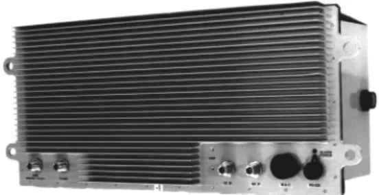
Figure 1-1 The ANASAT®-C VSAT transceiver (5W version shown)
Figure 1-3. Another view of the ANASAT®-5C Figure 1-2. The ANASAT®-20C, showing cooling fan
The ANASAT®-C VSAT series C-Band transceivers are designed for continuous out- door duty in all types of environments. Ideally suited for SCPC, MCPC, and DAMA applica- tions, the ANASAT®-C series transceivers trans- mit in the 6 GHz frequency range and receive in the 4 GHz range.
The ANASAT®-C VSAT transceivers inte- grate all necessary functions, including the solid-state power amplifier (PA), into a small, highly integrated outdoor package. The only ca- bling required to the indoor plant are the IF and AC power cables. The LNC connects to the transceiver with a single coaxial cable.
Designed to interface with any 70 MHz modem, the ANASAT®-C VSAT transceiver may be used in a wide variety of communication net- works. The earth stations may be configured in Star, Mesh, or Ring networks and with the op- tional Station Management System (SMS) tied
Introduction 1-2 A
NAC
OMANASAT
®–C Transceiver
A NA C OM 3072307
RF ELECTRICAL SPECIFICATIONS A. FREQUENCIES
Model
(1) Transmit RF N-connector C 5925 to 6425 MHz
(CPR-137 Flange optional on (1 MHz step size) 10, 20, and 40 W versions) EC 5850 to 6425 MHz (1 MHz step size)
XC 6700 to 7100 MHz
(500 kHz step size)
RC 5975 to 6475 MHz
(1 MHz step size)
PC 6425 to 6725 MHz
(1 MHz step size)
(2) Receive RF C 3700 to 4200 MHz
(CPR-229G Flange on LNC) (1 MHz step size)
EC 3625 to 4200 MHz
(1 MHz step size)
XC 4500 to 4800 MHz
(500 kHz step size)
RC 3650 to 4150 MHz
(1 MHz step size)
PC 3400 to 3700 MHz
(1 MHz step size) (3) Transmit IF (N-connector) all 52 to 88MHz (70 ± 18 MHz) [ or 104 to 176 MHz (140 ± 36 MHz) optional ] (4) Receive IF (N-connector) all 52 to 88MHz (70 ± 18 MHz) [ or 104 to 176 MHz (140 ± 36 MHz) optional ] B. RF POWER LEVELS
(1) Receiver Output
Intermod. By-Product –35 dBc max., measured
with two carriers @ -89 dBm, 30 kHz apart (2) Transceiver Input –40 to –20 dBm; +20 dBm max.
(3) Transceiver Output
(a) + 25ºC at Transmit RF Connector 1dB COMP. PT
-0 (0 dBm) 0 dBm min.
-2 (2 watt) +33 dBm min.
-5 (5 watt) +37 dBm min.
-10 (10 watt) +40 dBm min.
-20 (20 watt) +43 dBm min.
-40 (40 watt) +47 dBm min.
(b) Gain Variation, –40ºC to +50ºC @ Transmit RF and under all conditions
± 1.5 dB (c) Intermodulation By-Products (IP) (measured at a power
output of 9dB composite below the P–1dB spec) –33 dBc max.
Typical Operating Parameters
A NA C OM 3072307
A
NAC
OMANASAT
®–C Transceiver 1-3 Introduction
RF ELECTRICAL SPECIFICATIONS, continuedC. RECEIVER GAIN
(1) Overall Gain (at +25ºC) 85 to 100 dB
(M & C controlled)
(2) Gain Variation under all conditions ± 1.5 dB
D. RECEIVER NOISE FIGURE (standard) 0.9 dB (65ºK) max.
(optional) 0.63 dB (45ºK) max.
(optional) 0.5 dB (35ºK) max.
E. INSTANTANEOUS BANDWIDTH
(1) Receiver RF to IF 70 + 18 MHz
[ or 140 + 36 MHz optional ]
(2) Transmitter IF to RF 70 + 18 MHz
[ or 140 + 36 MHz optional ] F. IMPEDANCE
(1) Receiver Output (J4) 50Ω; (75Ω optional)
(2) Transmitter Input (J3) 50Ω; (75Ω optional) G. SYNTHESIZERS
(1) Tuning Step Size 1 MHz, except 0.5 MHz X0
(M & C controlled) (2) Phase Noise (offset from carrier) –60 dBc / Hz @ 100 Hz –70 dBc / Hz @ 1 kHz –80 dBc / Hz @ 10 kHz –90 dBc / Hz @ 100 kHz H. FREQUENCY REFERENCE
Stability over temperature
–30ºC to +50ºC 1 x 10⁻⁸
Aging 1 x 10⁻⁹ / day
RF / IF CONNECTOR DESIGNATIONS
A. Antenna (Receive Input, LNC/TR Filter) CPR-229G Flange
B. Transceiver Receive Input N-Type-Female
C. LNC Output N-Type-Female
D. Receiver IF N-Type-Female
E. Transmit IF N-Type-Female
F. Antenna (Transmit Output) N-Type Female
(CPR-137 Flange optional on 10, 20, and 40W versions)
Introduction 1-4 A
NAC
OMANASAT
®–C Transceiver
A NA C OM 3072307
INTERFACE ELECTRICAL SPECIFICATIONS
(1) Power Requirement 100 to 240 VAC
50/60 Hz (2) Total Power Consumption
0 dBm 23 VA typ.
2 W 47 VA typ.
5 W 82 VA typ.
10 W 150 VA typ.
20 W 225 VA typ.
40 W 350 VA typ.
INTERFACE CONNECTION DESIGNATIONS
(1) Ports 2 each RS-232 or,
1 RS-232 & 1 RS-485 (2) Protocol w/ RS-232 port supports any “dumb” terminal w/ RS-485 port supports addressed, packetized data per ANACOM SMS software specifications (3) Alarm Relays Form-C for Major and Minor alarms; isolated.
Optional independent TX and RX relay alarms.
(4) Visual Indicators Flashing GREEN LED indicates active power RED LED indicates summary alarm MECHANICAL SPECIFICATIONS
A. WEIGHT
(1) Transceiver 0 dBm output 20 lbs ( 9.1 kg)
2 W and 5 W output 27 lbs (12.3 kg)
10 W and 20 W output 34 lbs (15.4 kg)
40 W output 38 lbs (17.3 kg)
(2) LNC 2.0 lbs (0.9 kg
B. SIZE
(1) Transceiver 0 dBm, 2 W, 5 W output 21.6" x 9.0" x 7.0"
(549 x 229 x 178 mm) 10 W, 20 W output 21.6” x 9.0” x 12.1”
(549 x 229 x 307 mm)
40 W output 21.6” x 9.0” x 13.9”
(549 x 229 x 353 mm)
(2) LNC 3.7" x 2.8" x 3.9"
(91x 71 x 99 mm)
A NA C OM 3072307
A
NAC
OMANASAT
®–C Transceiver 1-5 Introduction
MECHANICAL SPECIFICATIONS (con’t.)C. SURFACE FINISH
Painted Surface
(a) Color (per FED-STD-595A, Spec. # 25630) Light Gray (b) Final Coating: Powder
Unpainted Surfaces: Chem. Film per MIL-C-5541, Class 3
ENVIRONMENTAL SPECIFICATIONS
A. AMBIENT TEMPERATURE CONDITIONS
(1) Operating –40 to +50°C
(2) Storage –60 to +75°C
B. ALTITUDE 15000' ASL max. (4560m)
C. RAIN 20" / hour (508mm/hr)
D. WIND 150 MPH (250km/hr)
E. VIBRATION
(1) Operating 1.0 G random
(2) Survival 2.5 G maximum random
F. SHOCK
(1) Operating 10 G
(2) Survival 40 G max.
NOTE: Operating parameters subject to change without notice.
Introduction 1-6 A
NAC
OMANASAT
®–C Transceiver
A NA C OM 3072307
A NA C OM 3072307
A
NAC
OMANASAT
®–C Transceiver 2-1 Installation
Section 2. Installation
The ANASAT®-C transceiver consists of the transceiver, the Low Noise Converter (LNC), and the LNC interconnection cable.
This chapter contains the general require- ments for installing the transceiver and LNC on the antenna and making the cable and
waveguide connections. Specific mounting methods may vary considerably depending upon particular antenna and site characteristics.
Refer to the antenna manufacturer’s instruc- tions for more detailed instructions.
ANASAT®-C transceivers are designed for installation and setup without removing the cover. The transceiver may be completely ini- tialized for normal operation using an ASCII terminal or a local computer.
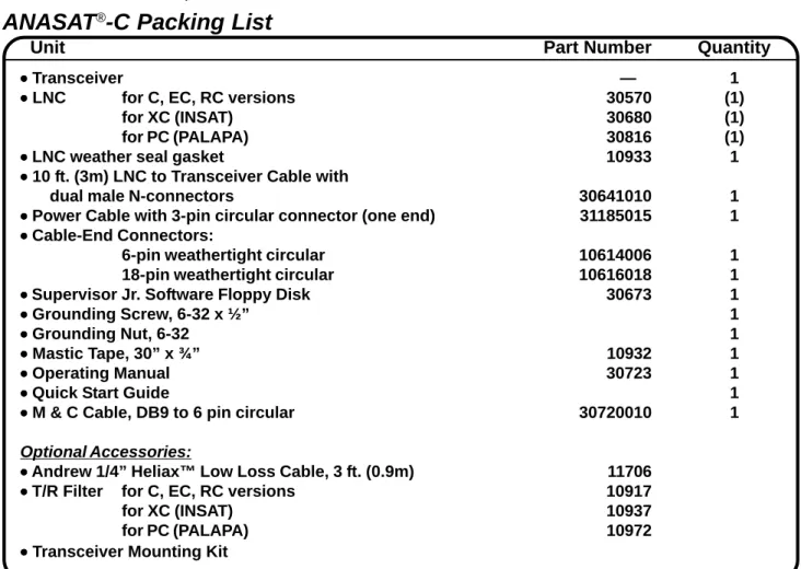
Table 2-1. ANASAT®-C Packing List
!
Removal of any cover may jeopar- dize the weather seal which may cause problems later.
Unpacking
Check to make sure that the transceiver has not suffered any damage in shipment.
Compare contents of the crate to ensure items received match those listed on the packing slip.
Retain all shipping containers for future use.
Tools and Test Equipment
Have on-hand a standard electrician’s tool kit and any tools listed in your antenna installa- tion instructions.
ANASAT
®-C Packing List
Unit Part Number Quantity
••••• Transceiver — 1
••••• LNC for C, EC, RC versions 30570 (1)
for XC (INSAT) 30680 (1)
for PC (PALAPA) 30816 (1)
••••• LNC weather seal gasket 10933 1
••••• 10 ft. (3m) LNC to Transceiver Cable with
dual male N-connectors 30641010 1
••••• Power Cable with 3-pin circular connector (one end) 31185015 1
••••• Cable-End Connectors:
6-pin weathertight circular 10614006 1
18-pin weathertight circular 10616018 1
•
• •
• • Supervisor Jr. Software Floppy Disk 30673 1
••••• Grounding Screw, 6-32 x ½” 1
••••• Grounding Nut, 6-32 1
••••• Mastic Tape, 30” x ¾” 10932 1
••••• Operating Manual 30723 1
••••• Quick Start Guide 1
••••• M & C Cable, DB9 to 6 pin circular 30720010 1
Optional Accessories:
•
• •
• • Andrew 1/4” Heliax™ Low Loss Cable, 3 ft. (0.9m) 11706
•
• •
• • T/R Filter for C, EC, RC versions 10917
for XC (INSAT) 10937
for PC (PALAPA) 10972
••••• Transceiver Mounting Kit
A NA C OM 3072307
Installation 2-2 A
NAC
OMANASAT
®–C Transceiver
LNC
Be sure the LNC unit is properly termi- nated prior to operation. Ensure all the correct waveguide gaskets are used to prevent water damage.
Site Considerations
Peculiar installation requirements of any particular site is the responsibility of the system operator. ANACOM can engineer an optional installation mounting kit, customized for your site and hardware. Contact ANACOM for de- tails.
Antenna
The transceiver must be attached to some form of mounting structure which is usually the antenna feed boom or the antenna bracket structure. Specific mounting procedures will de- pend on the antenna used. The transceiver and LNC are designed to be mounted on most an- tennas. Locate and install the antenna accord- ing to the antenna manufacturer’s instructions.
Choose an area that is free of extraneous inter- ference from motors and electronic equipment and has a clear line-of-sight from the antenna to the satellite.
Lightning arrestors should be used at the site to protect personnel and equipment. Size 3/0 or 4/0 stranded copper wire should be used to bond the transceiver to the antenna frame and to the lightning protection ground rod.
Power Requirements
The ANASAT®-C transceiver requires a power source which supplies 110 VAC or 220 VAC at 50 or 60 Hz, through a circuit breaker.
Specific circuit breaker size will depend on which transceiver is being used. To assure un- interrupted service, some method of back-up AC power is recommended. Installing surge ar- restors and AC power line filters will reduce volt- age surges from the AC power input. .
NOTE: AC TRANSIENTSANDSURGESMAYCAUSEDATA TRANSMISSIONERRORSANDLOSSOFSYNCHRONIZATIONINTHE TRANSCEIVERSYNTHESIZERSAND/ORTHEEXTERNALMODEM EQUIPMENT.
Safety Precautions
General
Ensure the ANASAT®-C transceiver and LNC are properly grounded. Do not rely on co- axial cable shields for the ground connection.
If the cover is removed from any ANACOM product, ensure that all:
• gaskets are intact and free of damage prior to reinstallation
• mounting screws are properly installed Ensure all connectors are properly water- proofed.
Power Supply
Confirm that AC Power is disconnected be- fore removing the transceiver or LNC cover.
Transceiver
Take adequate precautions to ensure the ANASAT®-C transceiver does not transmit a signal until it has been properly connected and set up for authorized frequencies and power levels. The transmitter is normally shipped from the factory with TX ON !
!
Observe normal safety precautions when operating this equipment.
Power Amplifier
Be sure the transceiver TX OUT port is properly terminated prior to operation. Ensure all the correct waveguide gaskets are used to prevent water damage.
TO ENSURE PROTECTION OF PERSONNEL AND EQUIPMENT, USE CARE DURING AN- TENNA INSTALLATION AND WHENEVER WORKING ON OR AROUND THE SYSTEM.
!
Transmitter RF output power levels are adequate to cause blindness or other serious injury to body tissues.
Use caution when working around the transceiver or antenna when the transmitter is active.
A NA C OM 3072307
A
NAC
OMANASAT
®–C Transceiver 2-3 Installation
Transceiver Mounting Considerations
The ANASAT®-C transceiver must be mounted such that:
1. Sufficient support is afforded the trans- ceiver to minimize the effects of an- tenna sway in strong winds.
2. Air movement is possible across the heat sink fins. Ideally, the fins should be aligned vertically, but this is not re- quired.
NOTE: The length (and associated RF losses) of the interconnecting cables must be considered when determining the location of the transceiver and LNC.
Transceiver Mounting
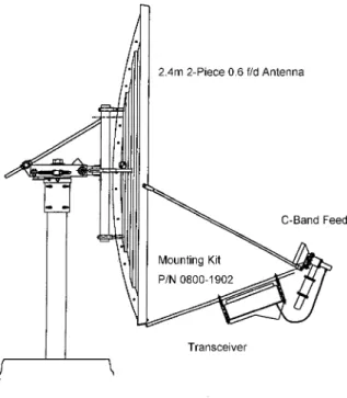
The ANASAT®-C transceiver is designed for mounting in any position. For optimal heat sink action, the heat sink fins should be vertical, or as nearly vertical as is practical, with the fins mounted on top. Figure 2-1 shows a common installation example where the transceiver is mounted on the antenna feed support arm.
Figure 2-1. Typical transceiver mounting.
When mounting the transceiver, allow enough room to adjust the antenna’s azimuth and elevation. Throughout installation and dur- ing any polarization, azimuth, or elevation ad- justment, ensure the power cables, IF cables, and any waveguide parts are not crimped or pinched.
Grounding
Electrical bonding (grounding) of the trans- ceiver is required to prevent possible damage from lightning or other induced electrical surges.
The transceiver is provided with both an M3, and a #8 grounding point. It is recom- mended that heavy guage copper wire or cop- per braid be used to bond this unit to the earth ground (grounding rod) using the most direct (shortest) route possible.
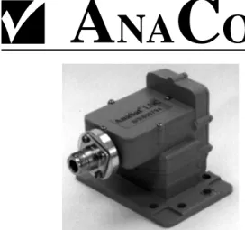
LNC/TR Filter Mounting
The LNC is shown in Figure 2-2. Normally the LNC is directly bolted to the antenna RX feed. In some situations, additional transmit-to- receive isolation may be required to achieve true low-noise receive operation. In that case, the optional TR filter (Figure 4-3) should be bolted between the LNC and the antenna re- ceive port. An appropriate waveguide gasket must be included at both ends of the TR filter.
Connect one end of the coaxial cable with male N-connectors (included) to the LNC. Refer to the note at the end of this section regarding wa- tertight connections. Route the 10-foot cable to the transceiver and connect to the LNC N-con- nector. Longer or shorter cable lengths may be used; contact ANACOM for details.
A NA C OM 3072307
Installation 2-4 A
NAC
OMANASAT
®–C Transceiver
2. 70MHz Modem
Attach a coaxial cable with male N-con- nectors between the transceiver’s TX IF (see Figure 2-3) and the modulator IF OUTPUT. Make sure that the connections are weather-tight.
Attach a coaxial cable with male N-con- nectors between the transceiver’s RX IF (see Figure 2-3) and the demodulator IF INPUT. Make sure that the connections are weather-tight.
3. AC Power
Attach the AC input cable to the 3-pin connector on the transceiver. Run the AC cable to the power source but do not at- tach yet. The supplied power cable has a three-pin weather-tight circular connector attached to one end. The other end is ter- minated with flying leads. Attach the proper AC power connector for your loca- tion to the other end of this cable.
Color code:
Black ... AC Hot power lead White ... AC Neutral power lead Green ...Ground
4. LNC
Attach the RF cable between the LNC connector and the transceiver LNC input connector. If a longer cable is required, insure that the replacement cable is de- signed for low loss at microwave frequen- cies. Maximum loss of the LNC cable must be 5 dB or less at 5 GHz!
5. Terminal Connections
A data terminal or a computer with termi- nal software connects to the ANASAT®-C via either RS-232 or RS-485 serial ports.
Appendix C shows the pinout of the serial outputs. Both 6-pin and 18-pin weather- tight circular connectors are included. An optional serial computer cable is available from ANACOM.
Figure 2-2. LNC assembly.
Cable and Waveguide Connections
Cabling Requirements
Local regulations may require that cables in occupied buildings be installed in steel con- duit. Local government agencies may waive this requirement for the use of Plenum cables, which are standard cables entirely encased in solid Teflon. Check the codes in your area.
NOTE: EQUIPMENTOUTAGESDUETOFAULTY CABLEMATERIALSORINSTALLATIONARENOTCOVERED BYYOURWARRANTY.
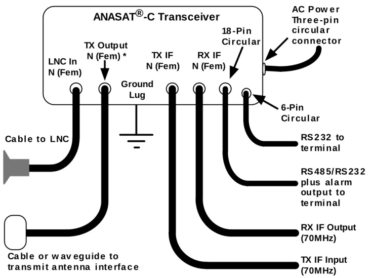
Figure 2-3 provides the cabling diagram for the ANASAT®-C transceiver.
1. Transmitter Feed
Connect a section of low loss cable with a type N connector between the OMT trans- mit port and the transceiver’s transmit output, TX OUT. Ensure the connections are weather-tight.
For transceivers with the CPR-137 flange option, connect a section of flexible CPR- 137G waveguide between the antenna OMT transmit port and the transceiver’s transmit output, TX OUT. (Waveguide should be attached to the antenna feed per manufacturer’s instructions). Ensure a gasket is fitted at each flange.
A NA C OM 3072307
A
NAC
OMANASAT
®–C Transceiver 2-5 Installation
AC P ow e rThr e e -pi n ci rc ul a r connec tor
Ca bl e to LNC
Ca bl e or w av eguide to
tr a ns m i t a nte nna i nte rfa c e TX IF Input
(70MHz) RX IF Output (70MHz)
RS 48 5/ RS 23 2 pl us al a rm ou tput to te r mi nal RS 2 32 to te r mi nal LNC In
N (Fem)
TX Output N (Fem) *
18 -Pi n Ci r cul ar
6-Pin Ci r cul ar RX IF
N (Fem) TX IF
N (Fem)
ANASAT®-C Transceiver
* CP R-1 3 7 G Wav e gui de Fl ange i s opti onal on 10 W and 2 0 W m ode l s . Ground
Lug
Figure 2-3 ANASAT®-C Cabling Interconnection Diagram.
Final Check
Recheck all bolts and cabling. Refer to fig- ure 2-3 to verify cable connections.
After all other connections have been made, connect the AC power cord to an active outlet.
Water Resistance Wrap
The application of moisture-resistant wrap (mastic tape) to all connectors is recommended to prevent water entry and resultant water dam- age. Apply the mastic tape as follows:
1. Ensure that all connectors are tight.
2. Pre-cut the mastic tape to the desired size and remove the protective wax liner from the tape.
3. Center the tape on the connector to be sealed and wrap the tape tightly around the connector. Squeeze the tape tightly and ensure that both ends of the tape have formed around the connector and the cable.
4. Apply the mastic tape to all connectors that may be exposed to moisture.
A NA C OM 3072307
Installation 2-6 A
NAC
OMANASAT
®–C Transceiver
Figure 2-4. Transceiver cable connectors.
A NA C OM 3072307
A
NAC
OMANASAT
®–C Transceiver 3-1 Operation
Preliminary Steps
After the ANACOM®-C hardware is mount- ed and verified, the antenna must be aimed to- ward the desired satellite. Follow the antenna/
mount manufacturer’s instructions, using coor- dinates provided by the satellite operator. Do not transmit until you have received authoriza- tion from the satellite network operation center, and a transmit power level from its engineering staff.
Terminal Connection and Configuration
Autolink:
The Anacom M&C features automatic baudrate sensing on the serial ports. If wrong baudrate is detected, the M&C will drop to 1200 baud and wait for user to move to 1200 baud.
Anacom provides a diskette with both our Su- pervisor® and Supervisor Jr.® software on it, that will perform the autolink with the ODU auto- matically, regardless of the last used settings.
Connect a terminal or computer running terminal emulation software to either serial port.
Generally, COM 0 (using the 6-pin circular weathertight connector) is used for on-site maintenance and control. COM 1 is often used in its RS-485 mode, with multi-unit, packetized protocol and differential mode signals good for moderately long distance (up to 4000 feet or 1200m) remote control. Either port or either se- rial protocol can be used to accomplish setup.
Set the terminal to 1200 baud, eight data bits, no parity, and one stop bit (1200,N,8,1 proto- col). Refer to Appendix C for wiring diagrams for the COM ports.
Frequency Programming
TXC; RXC
The transmit and receive frequencies are set independently using the TXCHAN (TXC)
and RXCHAN (RXC) commands. Refer to Ap- pendix E for a table of channel numbers versus frequency. NOTE: Appendix E assumes an IF of 70 MHz for both TX IN and RX OUT. Add or subtract any difference between the actual IF and 70 MHz to determine the exact RF frequen- cy employed.
TXF; RXF
Direct frequency entry in MHz can also be done by typing TXF**** or RXF**** where ****
are the transceiver frequencies for 70 MHz (or 140 MHz) TXIF & RXIF.
Operating frequencies for standard C-band channels are calculated with the following for- mulas:
fTX = TX IFIN + 5854 + Ch# MHz fRX = RX IFOUT + 3629 + Ch# MHz
For example, if the following commands are given to the transceiver:
RXCHAN 50 TXCHAN 50
Then with a TX IN intermediate frequency of 72.5 MHz the result is an output frequency of 5976.5 MHz. Likewise, with an RX OUT IF of 67.5 MHz , then the received RF frequency is 3746.5 MHz.
For XC (INSAT) frequencies, the formulas are:
fTX = TX IFIN + (13259 + Ch# ) / 2 MHz fRX = RX IFOUT + (8859 + Ch# ) / 2 MHz
NOTE: XC CHANNELSPACING (STEPSIZE) IS 0.5 MHZ. For RC (Russian) frequencies, the formu- las are:
fTX = TX IFIN + 5904 + Ch# MHz fRX = RX IFOUT + 3579 + Ch# MHz
Section 3. Operation
A NA C OM 3072307
Operation 3-2 A
NAC
OMANASAT
®–C Transceiver
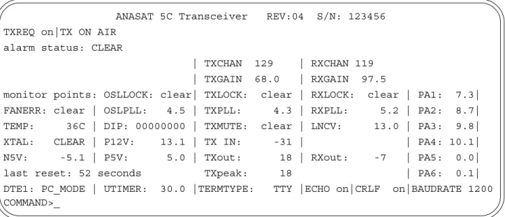
Figure 3-1. Remote M & C terminal screen display.
ANASAT 5C Transceiver REV:04 S/N: 123456 TXREQ on|TX ON AIR
alarm status: CLEAR
| TXCHAN 129 | RXCHAN 119
| TXGAIN 68.0 | RXGAIN 97.5
monitor points: OSLLOCK: clear| TXLOCK: clear | RXLOCK: clear | PA1: 7.3|
FANERR: clear | OSLPLL: 4.5 | TXPLL: 4.3 | RXPLL: 5.2 | PA2: 8.7|
TEMP: 36C | DIP: 00000000 | TXMUTE: clear | LNCV: 13.0 | PA3: 9.8|
XTAL: CLEAR | P12V: 13.1 | TX IN: -31 | | PA4: 10.1|
N5V: -5.1 | P5V: 5.0 | TXout: 18 | RXout: -7 | PA5: 0.0|
last reset: 52 seconds TXpeak: 18 | PA6: 0.1|
DTE1: PC_MODE | UTIMER: 30.0 |TERMTYPE: TTY |ECHO on|CRLF on|BAUDRATE 1200 COMMAND>_
For PC (PALAPA) frequencies, the formu- las are:
fTX = TX IFIN + 6354 + Ch# MHz fRX = RX IFOUT + 3329 + Ch# MHz
Both fTX and fRX may be directly entered and displayed via the M & C by using the TX- FREQ and RXFREQ commands. These com- mands will change the terminal display from channel number to RF frequency. These fre- quencies assume exactly 70 MHz IF.
Antenna Adjustment
Do not transmit while adjusting the antenna position.
Follow the antenna manufacturer’s instruc- tions for antenna position adjustment. For final alignment, contact the satellite operator and get the correct polarization, azimuth, and elevation of the satellite and also confirm the desired transponder is operational.
Apply power to the ANASAT®-C. While the transceiver requires about 5 minutes for the OCXO to reach full stability, antenna adjust- ments may be performed by monitoring other signals, such as beacons, immediately.
Connect a spectrum analyzer to the RX IF output. Set the ANASAT®-C to the desired fre- quency using the RXCHAN (or RXFREQ) com- mand, as described above. While monitoring the IF output for signals, slowly sweep the an- tenna through azimuth and elevation. Adjust an- tenna position for maximum signal strength.
M & C Operation
Terminal Display
The M & C terminal display gives a com- plete accounting of transceiver alarms and sta- tus. The display is sent to the terminal every 30 seconds. This interval can be changed with the UTIMER command. (See Appendix A).
The top line shows the transceiver model and serial number.
The second line gives the primary trans- ceiver operating parameters:
• status of the TXREQ setting: “ON” or
“OFF”
“ON” indicates the transceiver will transmit when all major transmitter alarms are cleared. This is the normal setting.
“OFF” indicates the transmitter will not turn on even if all alarms are clear.
!
A NA C OM 3072307
A
NAC
OMANASAT
®–C Transceiver 3-3 Operation
• Transmitter status is either “TX ON AIR” or
“TX OFF AIR”
The third line gives a summary alarm indi- cation. The alarm can be “CLEAR”, “MINOR”, or “MAJOR”. See Appendix B for specific alarms.
The fourth and fifth lines give TX and RX channel (or frequency) and gain values.
• TXCHAN number is the actual transmit channel selected.
• TXFREQ number is the actual transmit fre- quency for 70 MHz (140 MHz) input.
• TXGAIN is the actual transmit gain value selected in dB.
• RXCHAN number is the actual receive channel selected.
• RXFREQ number is the actual receive fre- quency for 70 MHz (140 MHz) output.
• RXGAIN is the actual receiver gain value selected in dB.
The remainder for the display give detailed monitoring information as follows:
• OSL LOCK gives alarm status of the OSL phase locked loop; NORMAL or FAULT
• TXLOCK gives alarm status of the transmit phase locked loop; NORMAL or FAULT
• RXLOCK gives alarm status of the receive phase locked loop; NORMAL or FAULT
• FANERR gives alarm status of the cooling fan (ANASAT-10C and ANASAT-20C only).
• OSLPLL shows the actual VCO control volt- age of the offset loop.
• TXPLL shows the actual VCO control volt- age of the TX synthesizer.
• RXPLL shows the actual VCO control volt- age of the RX synthesizer.
• TEMP shows the internal heat sink temper- ature in °C.
• TXMUTE gives the status of the TX override circuits, any of which will turn off the trans- mitter.
• LNC shows the LNC supply voltage.
• DIP shows the settings of the internal DIP switches (8 bits). See Appendix D.
• XTAL gives the status of the internal refer- ence crystal. The two possible status are WARMING or NORMAL. By default, WARMING will disable the transmitter.
• P12V shows the internal 13 volt power sup- ply voltage.
• P5V shows the internal 5 volt power supply voltage.
• N5V shows the internal –5 volt power sup- ply voltage.
• UTIMER gives the present value of the user timer which controls the cycle time of the display in seconds.
• TXin shows the approximate transmitter in- put (TX IF) power level in dBm.
• TXout shows the approximate transmitter output power level in dBm.
• TXpeak shows the recent (60 sec) peak transmitter output power level in dBm.
• RXout shows the approximate composite receiver output power level in dBm.
• TERMTYPE gives the present terminal type selection. Options are: “TTY”, “VT52”, and
“VT100”.
• ECHO gives the present setting for the ter- minal echo function. When “ON”, the serial port will echo all characters typed. When this parameter is “OFF” then the port will not echo characters.
• CRLF gives the present setting for the serial port to issue a line feed (LF) after each car- riage return (CR). Options are “ON” or
“OFF”.
• BAUDRATE shows the present terminal communications speed setting in bits per second (bps).
• PA1 through PA6 give show the voltages for each stage of the transmitter power amplifi- er. Note that the 0C, 2C and 5C models do not use all six voltages.
A NA C OM 3072307
Operation 3-4 A
NAC
OMANASAT
®–C Transceiver
Gain Adjustments
Transmitter Gain
After the transceiver has warmed up for at least 5 minutes (OCXO warm-up) the transmit- ter may be activated. Set the transmit gain to achieve the desired output level (in dBm) with the transmit gain control, TXGAIN. Output pow- er is selectable in 1 dB steps. Smaller steps can be entered, for example: TXG 62.5 and the M&C will attempt to provide that gain as closely as possible.
Maintaining proper output power is vital for maximizing signal-to-noise ratios over the radio path. Low power levels produce noisy signals;
excessive power robs downlink strength from other stations sharing the transponder.
Adjust the transmitter gain to attain the de- sired output power level. Use a calibrated watt meter for this task. The M&C gives an uncali- brated reading of output power which is good for long term monitoring, but it is not intended to replace a calibrated meter.
When transmitting multiple carriers, run the output power with an output back-off suffi- cient to meet the spectral density mask require- ments.
Receiver Gain
Set receive gain by monitoring RX IF out- put level and adjust the RXGAIN parameter via the terminal. RXGAIN allow adjustment over a 15dB range, from 85dB to 100dB (including LNC gain), in 1 dB steps. Smaller step sizes can be entered, for example: RXG 87.5
Receiver gain should be set to a value where the desired receive signal is centered in the modem AGC range. At the same time, the composite signal, containing all received sig- nals in the transceiver passband, must not ex- ceed the modem’s maximum rated input level.
Account for IF cabling losses when calculating the RXGAIN value.
RX IF output is monitored by the M & C unit; a Summary alarm is generated if this out- put level drops below a specific level (generally when the LNC is not attached). The M & C
uses an internal detector on the RX output to monitor RX output power. This is shown in the terminal display window in dBm. The RX output power value shown is not accurate enough to rely on for measuring the desired signal. The detector is broadband and will respond to ALL signals in the transponder, including noise.
Receiver gain setting is usually not as criti- cal as transmit gain: excessive gain may cause modem receiver overloading and result in dis- tortion on the received signal; insufficient gain presents reduced signal-to-noise ratios. Ideal RX gain puts the desired IF signal amplitude near the midpoint of the modem AGC range.
Basic M & C Commands
1. Using the terminal, configure the trans- ceiver to the proper frequency:
RXCHAN nnn nnn ranges from 1 to 501 TXCHAN nnn nnn ranges from 1 to 501
(see Appendix E).
2. Configure receive gain and transmit gain.
RXGAIN nnn nnn ranges from 85 to 100 in 1 dB steps TXGAIN nn nn ranges from:
10 to 36dB [ANASAT-0C]
44 to 70dB [ANASAT-2C]
48 to 74 dB [ANASAT-5C]
51 to 77 dB [ANASAT-10C]
54 to 80 dB [ANASAT-20C]
57 to 83 dB [ANASAT-40C]
NOTE: GAINSETTINGSANDPOWERREADINGSARENOT INTENDEDTOREPLACEACALIBRATED POWER METER.
Transmit gain is adjustable in 1 dB steps;
to program 60 dB of gain, merely type:
TXGAIN 60 <cr>
For 60.5 dB of gain, type TXGAIN 60.5 <cr>
NOTE: THEDECIMALPOINTISONLYNECESSARYWHEN
0.5dB OFGAINRESOLUTIONISATTEMPTED. FRACTIONAL VALUESMAYBEREQUESTED, BUTONLYTHENEARESTWHOLE VALUEWILLBEDISPLAYED.
3. Enable the Transmitter:
TX ON (TX OFF takes the transmitter OFF air)
A NA C OM 3072307
A
NAC
OMANASAT
®–C Transceiver 3-5 Operation
Configuring the ANASAT
®-C Via Hardware
The optional hardware switch package is required for hardware configuration.
Although not recommended and rarely (if ever) necessary, the ANASAT®-C may be opened and configured via mechanical switches. Do not open the transceiver unless serial data commu- nications is impossible.
There are only two reasons to open the transceiver:
• The M & C is inaccessible via either of the two serial ports
• No terminal (or computer with terminal software) is available
Use extreme caution when open- ing the transceiver. Do not expose the unsealed transceiver or unpro- tected subassemblies to moisture.
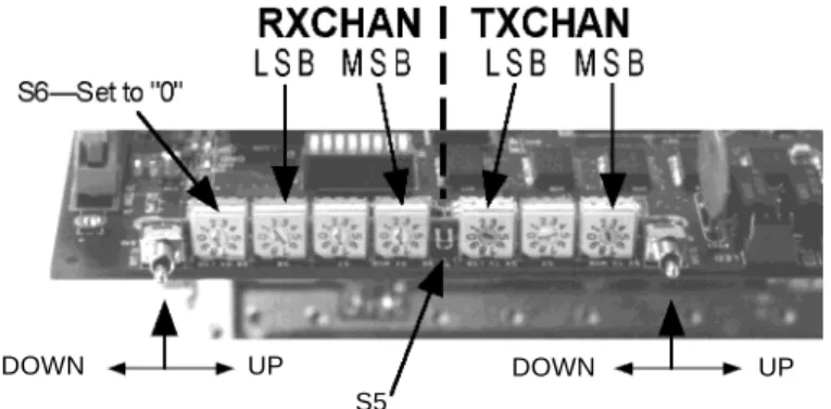
Open the transceiver by removing the screws attaching the heat sink to the bottom cover. Inside the ANASAT®-C trans- ceiver are two banks of three decade switches, one bank for TX channel selection, the other for RX channel selection. Momentary contact (spring loaded, center-OFF toggle switches) al- low manual receive gain and transmit gain con- trol. A quick push will change the gain by about 0.5 dB. Pushing and holding the switch will sweep the gain in rapid 0.5dB steps, and the longer the switch is held, the faster the step
rate. These controls are illustrated in Figure 3-2, and are described in Appendix D.
TX channels are selected by rotating the three decade switches to indicate the desired channel number (see Appendix E). For exam- ple, if channel 123 is desired, set the TX LSB switch to “3”, the center TX switch to “2”, and the TX MSB switch to “1”. Then push the center switch, S5. Note that the transceiver must have power applied when S5 is pressed.
Receive channels are selected in the same manner as the Transmit channels. Switch S6 must always be set to “0” if it is installed.
Between the receive and transmit channel selector switches is a momentary-contact push switch. Press this ENTER switch to activate the new transmit and receive channel selections and save the new data into nonvolatile FLASH memory. While gain adjustments are effective immediately, channel switching is not performed until the ENTER switch is pressed.
Transmit and receive gain adjustments are made by the same techniques used under M &
C terminal control, as described above. Re- member, any manual setting can be changed via the serial port later.
After manually configuring the transceiver, carefully mount the gasket and cover back onto the transceiver heat sink. Insure a watertight seal. The screws used to attach the cover to the heat sink must ALL be tightened securely.
Figure 3-2. The optional switch kit, used for manual transceiver control.
DOWN UP
S5
DOWN UP
!
A NA C OM 3072307
Operation 3-6 ANACOM ANASAT®–C Transceiver
ANASAT ® -C Quick Start Guide
1. Mount the transceiver and the LNC on the antenna.
2. Connect the cables shown in the drawing (See page 2-5).
3. Connect a terminal to a serial port, configured to 1200bps, 8 data bits, no parity, 1 stop bit, CR/LF Off. Connection diagrams are in Appendix C.
4. Install a proper power connector on the (included) power cable. Plug the cable into 110 or 240VAC, 50/60Hz. Verify the green LED on the transceiver is illuminated, indicating normal internal operation. The red LED is usually OFF. If illuminated, it indicates an error condition requiring attention. Refer to the ALARM command for details (Appendix A).
5. Using the terminal, configure the transceiver to the proper frequency:
RXFREQ nnnn (where nnnn is in MHz) or RXCHAN nnn (see Appendix E) TXFREQ nnnn (where nnnn is in MHz) or TXCHAN nnn (see Appendix E)
6. Configure receive gain and transmit output power:
RXGAIN nnn nnn ranges from 85 to 100
TXGAIN nn nn ranges from: 10 to 26 [ANASAT-0C] 44 to 70 [ANASAT-2C]
48 to 74 [ANASAT-5C] 51 to 77 [ANASAT-10C]
54 to 80 [ANASAT-20C] 57 to 83 [ANASAT-40C]
7. Enable the Transmitter:
TX ON (TX OFF takes the transmitter OFF air)
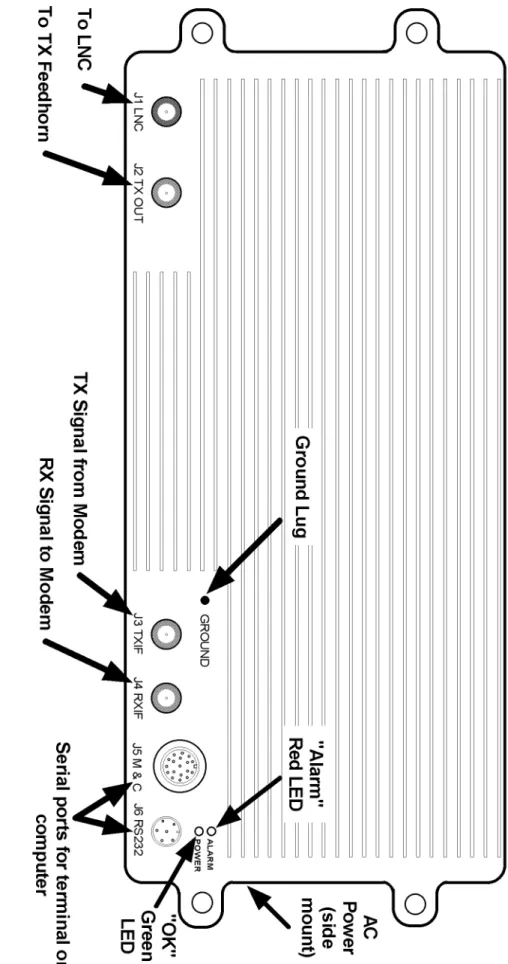
J3 TX I F J4RX I F J5 M & C J6 RS232 ALARM POWER
J1 LNC J2 TX OUT
GROUND
AC Power
(side mount)
To LNC
To TX Fe edhorn
TX Signal from Modem
RX Signal to Mode m Serial ports for terminal or computer
"OK"
Green LED
Ground Lug "Alarm"
Re d LED
That’s really all you must do! Good luck with your new ANASAT®-C transceiver!
A NA C OM 3072307
A
NAC
OMANASAT
®–C Transceiver 4-1 Theory of Operation
Section 4. Theory of Operation
serial communications are unavailable (optional switch package required).
Power distribution is controlled with each of several supply voltages and currents care- fully monitored. An active feedback negative bias voltage supply guarantees proper control of PA power.
Two LEDs, a flashing green indicating proper operation and a red warning of a Sum- mary alarm, are mounted on the transceiver for test-equipment-free status indication.
Low Noise Converter and Transmit Reject Filter
The receive signal from the antenna’s feed horn is fed via a CPR-229G waveguide coupler into the (optional) Transmit Reject (TR) filter (refer to Figures 4-2 and 4-3). This filter attenu- ates both the transmit signal and the receiver’s image (LO + IF), preventing severe overload of the LNC. TR filter passband characteristics are shown in Figure 4-4.
The LNC is bolted to the TR filter at the feed horn of the antenna and consists of two blocks: a C-band low noise amplifier (LNA) and a block converter that mixes the C-band receive signal with the 5 GHz local oscillator from the receive converter module to produce an L-band output.
The LNA consists of a three-stage GaAs FET preamplifier. Negative gate bias for the GaAs FETs is generated inside the block con- verter.
The amplified C-band signal is mixed with the 5 GHz local oscillator (LO) signal from the converter module in the transceiver. A filter passes the difference frequency and outputs this L-band signal to an N-connector. A cable carries this output to the converter module in- side the transceiver.
The ANASAT®-C transceiver outdoor unit (ODU) consists of five major blocks, as shown in Figure 4-1. These blocks are:
• Low noise converter (LNC) and Transmit Reject (TR) filter
• Transmit/Receive Converter
• Power Amplifier (PA)
• Monitor and Control Unit (M & C)
• Universal Input switch-mode power supply
Signal Path
Receive signals from the antenna feed through CPR-229G waveguide into the TR Fil- ter, which prevents the transmit signal and re- ceiver image frequencies from passing into the low noise converter (LNC). The LNC amplifies and mixes the C-band receive signal, outputting an L-band IF signal to the converter module.
The receive converter portion of the converter module synthesizes the proper mixer frequen- cies for the second converter, which outputs the (nominal) 70 MHz receive output at the RX IF N-connector on the transceiver.
Transmit signals at (nominally) 70MHz are input to the TX IF N-connector on the trans- ceiver. This signal is double converted to the desired C-band frequency in the converter mod- ule and output to the linear power amplifier (PA). PA output of up to 2W, 5W, 10W, or 20W, depending upon transceiver version, feeds the antenna.
Control and Power Systems
The microprocessor-based M & C unit monitors the transceiver’s parameters to insure proper operation and reliable, long term service.
Two serial ports provide local or remote termi- nal access. Manual control is available in event
A NA C OM 3072307
Theory of Operation 4-2 A
NAC
OMANASAT
®–C Transceiver
Figure 4-1. ANASAT®-C Transceiver Block Diagram BPF
BPFBPF BPFBPFBPFBPFBPF
BPFBPFBPFBPF HighStabilityOCXO TXGainSet1
70MHz1170MHz TXGainSet2
TXSynthesizer≈5GHz
RXSynthesizer≈5GHz ≈6GHz
1GHzIF 5GHzLO
70MHz RXGainSet
LNBPower TXIFIn(N)
RXIFOut
(N) (SMA)
(N) (N) (SMA) FemaleN-Connector(CPR-137WaveguideFlangeOptional,10W&20Wversions)
CPR-229GWaveguide PowerAmplifier
LNCTRFilter(opt.)ConverterModule Monitor&Control(M&C)Unit RXGainTXGainRXChanTXChanAlarmRelays Ser0RS-485RS-232 PowerSupplyACInput
PowerControl UARTAlarmRegister FLASHMemoryStatusRegisterControlRegisterA/DD/A StatusRegisterDataBus
AnalogI/OPowerDigitalI/OAnalogI/OPower ManualControl(OptionalSwitchPackagerequired)
OffsetSynthesizer
1.1GHz Ser1(RS-232)
Micro-processor
A NA C OM 3072307
A
NAC
OMANASAT
®–C Transceiver 4-3 Theory of Operation
Converter Module
The converter module (Figure 4-5) is lo- cated inside the transceiver and consists of two sections, the receive converter and the transmit converter. The converter module takes an ex- tremely stable 10 MHz reference signal from the Monitor & Control unit and synthesizes all necessary mixing frequencies.
Receive Converter Signal Path
The receive converter takes its input from the LNC via an N-connector on the transceiver (refer to Figure 4-6). A short coaxial cable con- nects the type-N connector on the heat sink to the converter unit itself. A diplexer at this input allows this single connector to perform three functions: signal IF input from the LNC, LO out- put to the LNC, and DC power to the LNC.
Only one coaxial cable is needed between the transceiver and the LNC. This cable carries three signals:
• L-band signal output from the LNC
• ≈5 GHz LO input from the converter
• +12V DC power from the converter module.
Combining and separation are accom- plished with and inductor for the supply voltage and a pick-off coupling for the LO.
Figure 4-2. The LNC
Figure 4-5. Converter Module Assembly.
Figure 4-4. TR Filter Passband Characteristics.
RX Passband RX image
TX output
Attenuation
Figure 4-3. The Optional TR Filter
A NA C OM 3072307
Theory of Operation 4-4 ANACOM ANASAT®–C Transceiver The L-band receive signal is extracted by
the input diplexer and is filtered by a mechani- cally-tuned 6-pole filter. A single-stage amplifier provides +10 dB of gain. Another mechanical filter cleans the signal before it is mixed with a 1.1GHz LO frequency, producing the (nominal) 70 MHz receive output. An L-C network selects only the 70 MHz mixer output and passes this signal to a variable gain amplifier. This variable gain amplifier is adjustable over a 15dB range and is operator-adjustable by terminal com- mands via the M & C unit. A final LC bandpass filter connects the variable gain amplifier to the 50Ω N-connector output on the ODU. An exter- nal 50Ω to 75Ω transformer is available from ANACOM as an option.
The +12V DC supply to the LNC is fused with a self-resetting “polyswitch”. This
polyswitch is located on the M & C board.
Frequency Synthesizers
The converter module generates all neces- sary frequencies with phase-locked-loop (PLL) synthesizers. All PLLs are referenced from a
single 10 MHz clock mounted on the M & C board. This master oscillator is a highly stable 10 MHz oven controlled crystal oscillator (OXCO) accurate to 1 x 10⁻⁸ Hz ( 0.01 Hz at 10MHz). This oscillator is fine tuned to compen- sate for normal aging effects automatically from the M & C unit.
Offset Loop
The first synthesized frequency is the 1.1GHz offset loop signal that is used by both the transmit and the receive converters. This signal is split and fed to the second receive mixer and the first transmit mixer.
Receive Synthesizer
The receive synthesizer generates the tun- able ≈5 GHz LO used by the LNC. Referring to Figures 4-6 and 4-7, the 1.1 GHz offset loop signal is applied to a x 4 multiplier and mixed with a 5 GHz VCO. The resulting 300 MHz to 800 MHz output is fed into a programmable di- vider and fed to a phase detector that compares it to the 10 MHz reference clock. Phase detec- tor output voltage is filtered and drives a 2.3 GHz to 2.7 GHz VCO. This frequency is doubled and fed into the previously mentioned mixer, closing the loop. Other C-band frequen- cies are generated by an almost identical cir- cuit.
Transmit Synthesizer
The transmit synthesizer generates a tun- able 4.75 GHz to 5.25 GHz LO used by the sec- ond transmit mixer to produce the final transmit output frequency. Referring to Figures 4-7 and 4-8, the 1.1 GHz offset loop signal is applied to
Ou tp ut V CO
M ix er 1. 1G H z × 4
10 M H z ÷ N
÷ M
Ph a se Det ec to r
Lo o p F i lt e r Figure 4-7. Phase-Locked Loop Frequency
Synthesizer Block diagram.
Figure 4-6. Converter Module, Receive Portion.
BPF
BPF BPF
BPF BPF BPF BPF BPF
BPF BPF BPF BPF
High Stability OCXO TX Gain Set 1
70MHz 1170 MHz
TX Gain Set 2
TX Synthesizer
≈ 5 GHz
RX Synthesi zer
≈ 5 GHz
≈ 6GHz
1GHz IF 5GHz LO
70MHz RX Gain Set
LNB Po wer RX IF Out
(N)
(N) (N)
CPR-22 9G Wave gui de
LNC TR Filte r (Opt.) Converte r Module
A NA C OM 3072307
A
NAC
OMANASAT
®–C Transceiver 4-5 Theory of Operation
a x 4 multiplier and mixed with a 5 GHz VCO.The resulting 300 MHz to 800 MHz output is fed into a programmable divider and fed to a phase detector that compares it to the 10 MHz refer- ence clock. Phase detector output voltage is fil- tered and drives a 2.3 GHz to 2.7 GHz VCO, which is frequency doubled and fed into the previously mentioned mixer, completing the loop.
Transmit Converter Signal Path
The Transmit converter takes the nominal 70 MHz signal input from a 50Ω N-connector on the transceiver (refer to Figure 4-8). (Note: an external 75Ω to 50Ω transformer is available from ANACOM as an option). This signal passes through an LC filter and into the trans- mit variable gain amplifier. This amplifier is gain-adjusted by a control voltage from the M &
C unit, and has a gain variation of 26dB in 1dB steps. Another LC bandpass filter removes any out-of-band noise and presents the signal to the first transmit mixer. This mixer adds the 1.1 GHz offset loop frequency to the TX IF, produc- ing a 1170 MHz nominal output. This L-band output passes through a mechanical filter into the second gain block. The signal amplitude is adjusted by a control signal from the M & C unit and the amplified signal flows through another mechanical filter.
The L-band output is now applied to the second transmit mixer, where it is combined with the 5 GHz transmit synthesizer output and be- comes a C-band signal of the desired frequency.
A mechanical bandpass filter selects the proper mixer product and applies it to a three-stage amplifier. A final mechanical filter is used before
the transmit signal is applied to the SMA jack that couples it to the PA.
Power Amplifier
ANASAT®-C series transceivers are avail- able in six versions, with maximum transmit out- put powers of 0 dBm, 2, 5, 10, 20, and 40 watts.
Four different power amplifier (PA) mod- ules are employed to economically achieve the different output ratings.
The 0 dBm unit “0W” transceiver has no power amplifier. The up converter output is fed directly to the outside with a type-N connector.
Construction
The PA module is a highly linear amplifier built on soft-board Duroid™ PC board substrate material silver epoxied inside a 0.75-inch thick machined aluminum block. This assembly is bolted to the center of the transceiver heat sink for excellent thermal conductivity. Power for each stage is provided via individual feed- throughs drilled into the machined block and has separate ferrite bead isolation for each con- nection. Aluminum bars securely fasten the soft board into the cavity.
2 Watt Module
The 2 watt PA module, which is similar to the 5 watt module shown in Figure 4.9 takes its input from the transmit converter on the con- verter module. This input handles up to +10 dBm and is connected to the converter board via coaxial cable using SMA connectors.
Figure 4-8. Converter Module, Transmit Portion.
BPF BPF BPF BPF BPF BPF
BPF BPF BPF BPF
High Stability OCXO TX Gain Set 1
70MHz 1170 MHz
TX Gain Set 2
TX Synthesizer
≈=5 GHz
RX Synthesi zer
≈=5 GHz
≈=6GHz
1GHz IF 5GHz LO
70MHz RX Gain Set
LNB Po wer TX IFIn
(N)
(SMA) (SMA)
Mal e N-Con necto r (CPR 1 37 Flange op t.
avai labl e o n 10W & 20W version s)
Power Amplifier
Converte r Module
A NA C OM 3072307
Theory of Operation 4-6 A
NAC
OMANASAT
®–C Transceiver
Output is applied to a SMA connector mounted on the soft board. A coaxial cable con- nects to a 50Ω N-connector mounted on the heat sink of the transceiver.A directional coupler and power detector monitors the output power level and reports to the M & C unit.
10 Watt Module
The 10 watt PA module, which is similar to the 20 watt unit shown in Figure 4-10, takes its input from the transmit converter on the con- verter module. This input handles up to +10dBm and is connected to the converter board via coaxial cable using SMA connectors.
Good RF grounding and thermal proper- ties are assured by the use of Teflon®
(Duroid™) PC board substrate material which is permanently attached to the cavity.
Transmit input is applied to a hybrid cou- pler which feeds a balanced two-transistor am- plifier. A second hybrid coupler converts this balanced output to a single-ended input for the four-stage amplifier.
This drive power is fed into another hybrid coupler and on into the two-transistor balanced final amplifier. This balanced output passes through another hybrid to combine the signal into a single-ended 10W output which is fed into a female SMA connector mounted on the
!
DO NOT ATTEMPT REPAIR OR REMOVE THE P.A. CIR- CUIT BOARD! SEVERE DAM- AGE WILL RESULT.
Figure 4-9 5W Power Amplifier Module.
Good RF grounding and thermal proper- ties are assured by the use of Teflon®
(Duroid™) PC board substrate material which is permanently attached to the cavity.
Transmit input is applied to a hybrid cou- pler which feeds a balanced two-transistor am- plifier. A second hybrid coupler converts this balanced output to a single ended input for the three-stage amplifier. Maximum final output power is a minimum of 2 Watts at the 1dB com- pression point.
Output is applied to a SMA connector mounted on the soft board. A coaxial cable con- nects to a 50Ω N-connector mounted on the heat sink of the transceiver.
A directional coupler and power detector monitors the output power level and reports to the M & C unit.
5 Watt Module
The 5 watt module, shown in Figure 4-9, takes its input from the transmit converter on the converter module. This input handles up to +10 dBm and is connected to the converter board via coaxial cable using SMA connectors.
Good RF grounding and thermal proper- ties are assured by the use of Teflon®
(Duroid™) PC board substrate material which is permanently attached to the cavity.
Transmit input is applied to a hybrid cou- pler which feeds a balanced two-transistor am- plifier. A second hybrid coupler converts this balanced output to a single-ended input for the four-stage amplifier. Maximum final output power is a minimum of 5 Watts.
A NA C OM 3072307
A
NAC
OMANASAT
®–C Transceiver 4-7 Theory of Operation
soft board. A coaxial cable connects to a 50ΩN-connector mounted on the heat sink of the transceiver. A directional coupler and detector diode monitors output power and reports to the M & C unit.
If the transceiver is configured with the optional CPR137 waveguide port, awaveguide launch is mounted under the heatsink and mates to the PA module v