Since a new module will be inserted into the existing network, the following rules must be followed: a) The designed module must be transparent to the operating laser signals and protocol from the OLT and ONU;. Since a new module will be inserted into the existing network, the following rules must be followed: a) The designed module must be transparent to the operating laser signals and protocol from the OLT and ONU;.
Performance Analysis of a Passive FTTH-PON System Using Hybrid OTDM/WDM Multiplexing
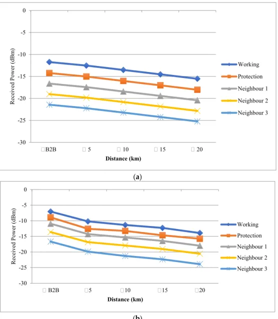
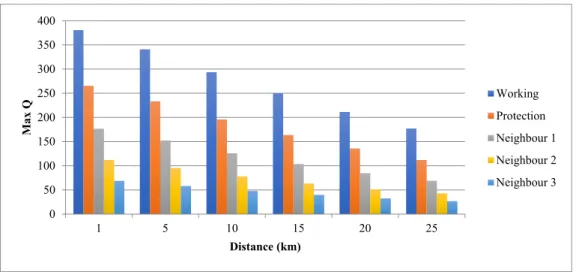
The graphs below show the diagram of the eye and the quality factor of the OTDM. Figure 12 shows the variation of the quality factor depending on the length of the fiber.
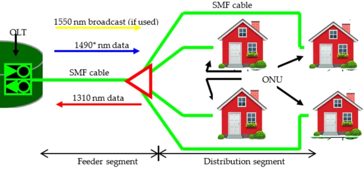
![Figure 1: passive point-to-point architecture [2].](https://thumb-ap.123doks.com/thumbv2/123dok/10838577.0/57.892.108.433.355.538/figure-1-passive-point-to-point-architecture-2.webp)
COMPARISON BETWEEN
RCORD BASED FTTH NETWORK
MASTER’S IN
INTERNETWORKING
SNEHPREET KAUR
ACKNOWLEDGMENT
ABSTRACT
FTTH
- WHAT IS FTTH
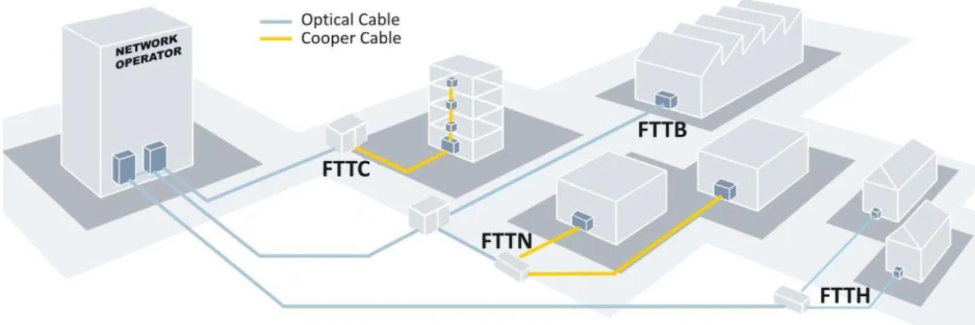
- FTTx Network Architecture
- FTTH TYPES
- POINT TO POINT (P2P)
- ARCHITECTURE
- Advantages of P2P Technology for FTTH
- POINT TO MULTIPOINT (THIS IS USED IN GPON)
- Architecture
- Advantages of P2MP/PON Technology for FTTH
- Benefits of FTTH over Traditional Methods
- METHODS TO ESTABLISH OPTICAL FIBER
FTTH stands for Fiber to the home network and is a fixed method used to access the network technologies. The base stations for the mobile network c) The customers in single family unit d) The area like schools, hospitals .. e) The security and proper functioning of it like alarms, cameras, sensors. For the best utilization of the existing fibers in specific topologies, the switches are not connected to the POP, but instead connected in a ring or chain structure.
Reference: https://www.excitingip.com/2496/what-is-ftth-fiber-to-the-home-advantages-of-p2p-vs-p2mpon-architectures/.
1.8 5G FIBER REQUIREMENT
FTTH NETWORK SHARING
- Duct sharing in North America
- SEWER SYSTEM
- WATER PIPES
To reduce the cost of the FTTH networks, one way is to share the channels. With the use of a flexible indoor channel it is possible to add more cables to this already congested channel, in this case three of the three alternative operators. With the installation of fiber optic cables, the sewerage system can be reached by more residents.
A microchannel is then installed between the two fixtures to create a gas-tight environment where fiber can be inserted without coming into direct contact with the water supply.
THE LARGEST INVESTORS IN THE FIBER
- HOW THEY ACHIEVED IT
FIBER CABLES FOR FTTH
CONCLUSION
PON TOPOLOGY
The network topology is the one in which nodes such as routers, switches are connected to other networks or to LAN (Local Area Network).
TYPES OF PON
- TDM PON
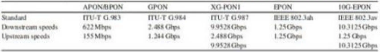
- An APON/BPON (ITU-T G.983) APON
Here, the traffic to and from is time-division multiplexed on the upstream and downstream wavelengths. Current systems use TDM, which involves APON, which is ATM-PON, BPON, which is broadband PON, GPON, which is Gigabit PON, which is mainly covered in my report, 10G PON, NG-PON, which is the next generation of PON. In the case of ATM, the upstream transmission is performed in bursts of ATM cells.
The delimiter is a pattern used to indicate the start of an incoming cell.
DOWNSTREAM AND UPSTREAM TRAFFIC TYPES
The table shows the Timeline for ATM development
LIST OF ATM RELATED ITU-T RECOMMENDATIONS
A BPON
B NG-PON
NG-PON1
Asymmetric 10G-PON
Symmetric 10G-PON
NG-PON2
- C EPON (IEEE 802.3ah)
It uses timers, a state machine for point-to-multipoint access control. At the base layer of the MCPC protocol, there is a point-to-point emulation sublayer. This sublayer at the MAC and the upper layer represent the P2MP network as a point-to-point connection.
There is another cost-effective quality of EPON, which is to preserve the Ethernet frame format that carries packets of variable length without fragmentation.
IMPORTANT DIFFERENCES BETWEEN GPON AND EPON
D 10GEPON
10G-EPON has 64B/66B line coding with the bit-to-baud overhead being reduced to about 3%. There are advanced transmitters and higher launch power in 10G-EPON to ensure sufficient signal-to-noise ratio (SNR) at the receiver side to recover the best data at a rate of 10 Gbps. With the increased launch power there should be an increase in the power consumption of the optical transmitter.
So, to accommodate 10 Gbps in the physical layer, the power consumption of the OLT and ONU can increase significantly.
WDM PON
In WDM PON, each user has access to its dedicated one or more wavelengths, therefore this gives every subscriber access to full bandwidth. WDM PON networks are more scalable and have better security as each home has access to its own wavelength. In a WDM PON network, each wavelength is a point-to-point link, which allows all links to run at different speeds and with different protocols, providing maximum flexibility.
Despite all these features, WDM PON is still expensive due to the specific wavelength assigned to each ONU.
OFDM PON
In WDM PON, there is simplified MAC layer control because the links between OLT and ONU in WDM PON are point-to-point, which do not require point-to-multipoint (P2MP) media access controllers. Since each subscriber has its own dedicated wavelength, an OLT that can support 32 ONUs must transmit 32 different wavelengths. So this means that this wavelength-specific feature is not so economical, as it will even result in high laser requirements compared to TDM PON if the same set of fixed-wavelength lasers are required for each ONU.
It is a tough competition compared to NG-PON2 because when combined with WDM, it can further increase the bandwidth.
ADVANTAGES OF OFDM PON
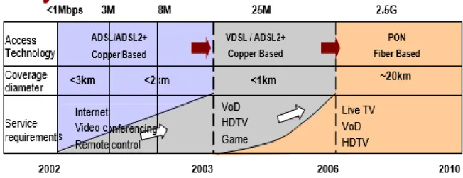
- EVOLUTION OF PON
- PARTS OF PON
- PON IMPLEMENTATION
- Fiber
- Drop Terminals
- The testing of PON Installation
- The connection of the connector and how it is maintained
- IMPORTANT THINGS TO NOTICE WHILE THE TESTING
- ADVANTAGES OF USING PON
Patch cords came in a wide range of colors so they can be easily differentiated and are relatively short. Fiber optic cables can be implemented using the most suitable aerial or underground installation techniques. Drop terminals are used for easy access to service connection, distribution and if used can be aerial, underground or located in an apartment building.
Referenca: https://www.cablinginstall.com/articles/print/volume-27/issue-2/features/special- report/good-fiber-optic-connections-start-with-the-ferrule.html.
CHAPTER-3 GPON
- WHAT IS GPON AND WHY IS IT USED 2. THE STANDARDS OF GPON
- GPON NETWORK MODEL REFERENCE 4. THE FUNDAMENTALS OF GPON
- THE FEATURES OF GPON
- GPON FRAME FORMAT AND MULTIPLEXING 7. GPON TECHNIQUES
- COMPONENTS OF GPON 9. GPON FTTH ARCHITECTURE
- GPON NETWORK PROTECTION MODES 11. POWER BUDGET
- WHAT IS GPON AND WHY IS IT USED
- THE STANDARDS OF GPON
- ITU-T G.984.1
- ITU-T G.984.2
- ITU-T G.984.3
- ITU-T G.984.4
- GPON NETWORK MODEL REFERENCE
- THE FUNDAMENTALS OF GPON
- THE FEATURES OF GPON
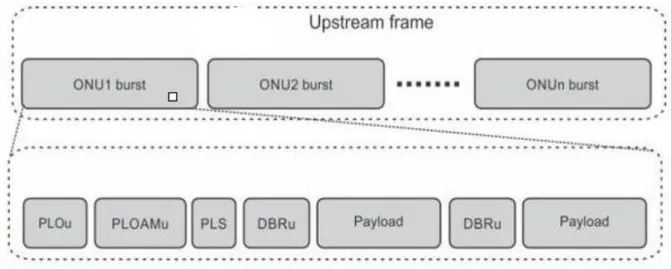
- GPON FRAME FORMAT AND MULTIPLEXING
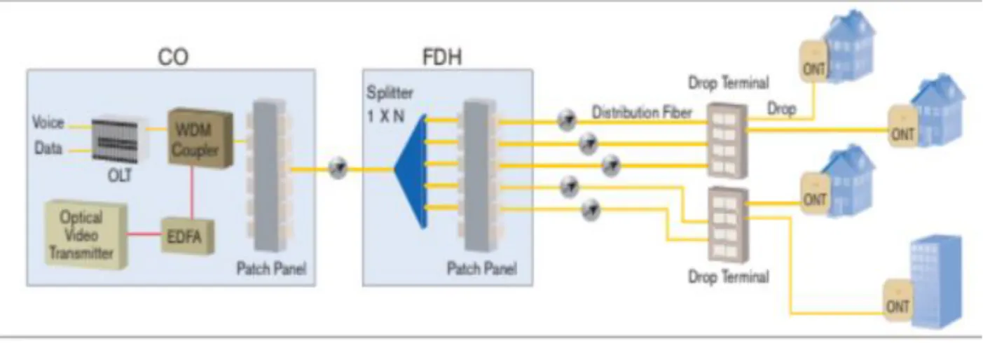
Optical Line Termination (OLT) and Optical Network Unit (ONU) are the only active transmission equipment in the GPON network. There is only one single-mode optical fiber strand from the main office running up to the passive optical power distributor, which is located near the users' location. When this optical fiber reaches the splitter, the splitter splits the optical power into N separate paths for the users.
GPON uses Wavelength Division Multiplexing (WDM) which has the facility of two-way communication over a single optical fiber.
3.6.1 (FROM ONU/ONT TOWARDS OLT): UPSTREAM TRAFFIC
- OLT 2. ONU
- FROM OLT TO ONU: DOWNSTREAM TRAFFIC
- GEM (GPON Encapsulation Method)
- SERVICE MAPPING UPSTREAM
- T-CONT
- GPON TECHNIQUES
- Ranging
- Burst optical or electrical technology
- Line encryption
- COMPONENTS OF GPON .1 OLT (Optical Line Terminal)
The T-CONT then uses time slots to send the GEM PDUs to the OLT for the upstream transmission. For the downstream transmission, based on the mapping rules between service and uplink port, the OLT will send Ethernet frames to the GPON service processing module. Multiple T-CONTs can be allocated by the OLT to the ONU when the long queue in the buffer is waiting for an ONU.
It is assigned by the OLT to the ONU to identify the entity carrying the traffic.
THE BLOCK DIAGRAM OF OLT
PON CORE-SHELL
Cross-connect shell
Service shell
ONT/ONU (OPTICAL NETWORK TERMINAL)/ (OPTICAL NETWORK UNIT)
There are several user network interface ports on the ONT for the service network interface that is connected to the OLT. For Residential ONT the UNI ports are: − . a) 10/100Base-T High Speed Internet (HSI) and video over IP b) Coaxial RF for RF video overlay systems. The GPON fiber is terminated by the ONU and has multiple user network interfaces for multiple subscribers.
For these types of cases, the UN UNI is connected to a network connection (NT) that is placed at the subscriber's end location.
SPLITTER
ONU can be a better option where the CAT-5 copper cable is already laid like the user in the campus like hospital or school or corporate offices. Basically, the ONT is a combination of functions of ONU and an NT in a single device which makes the ONT a cost-effective solution to provide the GPON services to local and single families. The distribution loss is the most important parameter considered for the FTTH network designer and is the span between the central office and the user or is the maximum optical budget allowed in the system.
Optical budget is the result of attenuation due to splices, connectors, optical fibers and splitters.
ODN (OPTICAL DISTRIBUTION NETWORK)
The passive optical splitter has features such as wide wavelength range, low insertion loss and uniformity, minimal size, high reliability and supporting network survival and security policies. Reference: https://community.fs.com/blog/abc-of-pon-understanding-olt-onu-ont-and-odn.html.
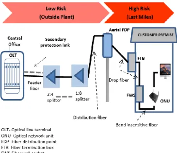
GPON FTTH ARCHITECTURE
In the distribution area, the distribution cable is used to connect the level-1 distributor to level-2. At the entrance to the residential area, the level-2 splitter is placed in a pole-mounted box called a Fiber Access Terminal. The level-2 splitter inside the FAT is used to connect with the subscriber premises in the user area by means of drop cables.
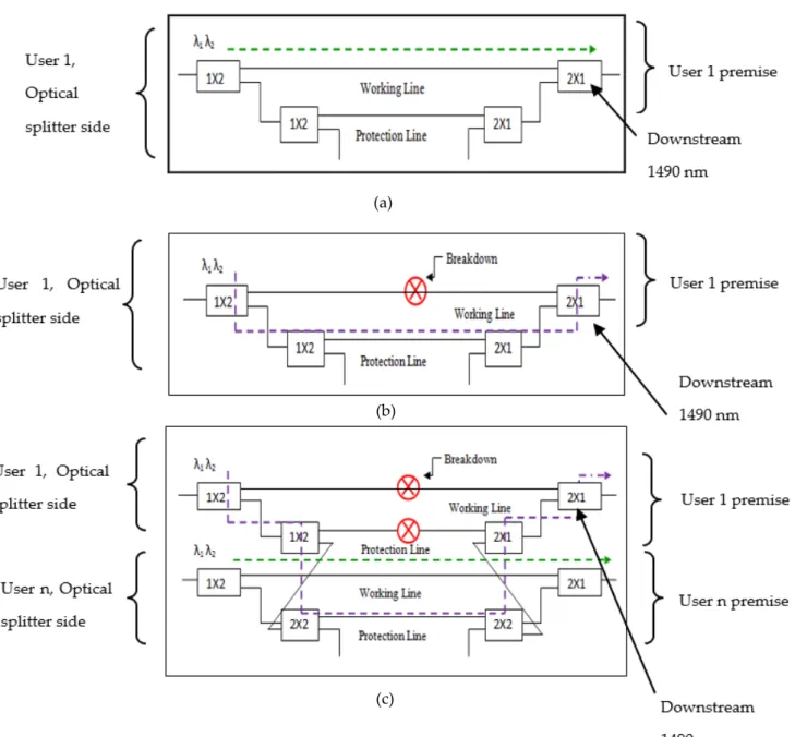
GPON NETWORK PROTECTION MODES
MIXED BACKUP
- Power Budget
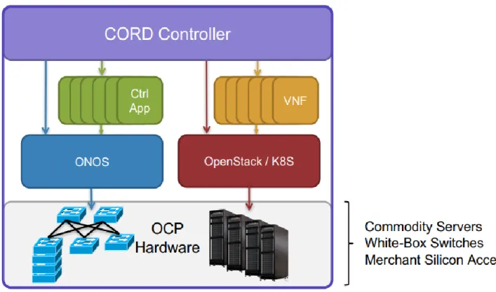
CORD
- INTRODUCTION TO CORD
- CORD ARCHITECTURE
- MCORD
- ECORD
- ACORD
Access is again something different and moving it to the cloud will again be a challenge. A lot of effort is put into the switching structure, which is a fundamental part of the CORD platform. In addition to the folding fabric of the spine of the sheet, one of the racks is a rack for ONU access cabinets.
Furthermore, it is extremely difficult to make changes to the current infrastructure for different needs or areas of remote adopters.
RCORD
- INTRODUCTION
- PURPOSE
- TRADITIONAL RESIDENTIAL ACCESS
- OVERVIEW OF DISAGGREGATED RESIDENTIAL ACCESS
- Detailed Residential CORD and its components
- vOLT
- ONOS applications
- Introduction to vSG
- Design Options
- The Design – Functionality
- The Design – Performance
- Subscriber API
- vRouter
- DESCRIPTION OF RCORD
- VOLTHA
On this edge, CO is really close to the end user, this is an advantage that gives us the possibility to introduce other third party services. One of the servers will run radius server and vOLT, which will "run on top" of the CORD software stack. Now traffic tagged with the user's assigned VLAN can flow from any device in the subscriber's home to the vSG.
This traffic from the CPE flows to the OLT blade and then through the fabric switch to the vSG of one of the commodity servers.
SDN AND NFV
- CORD 2. HERD
- FUNDAMENTALS OF SDN AND NFV
- THE ROLE OF SDN AND NFV IN RCORD
CORD's hardware has commodity servers that are connected using white box switches. Control plane traffic takes into account the router used to decide where its destination should be. With the help of an open interface, the control layer provides a centralized useful functionality that takes care of network mediation.
The infrastructure layer consists of the network components (NE) and components used to switch and forward the packet.
Selection of Neighborhood
DIAGRAM OF CITY OF LEDUC
MULTIWAY MAP
Multiway Map of the City to analyze the length of the cables required to create a network
- Details of the City of Leduc
- Implementation of GPON based FTTH Network
- Technical Aspect
- Civil Aspect
- R-CORD DEPLOYMENT
- Comparison between R-CORD and GPON based FTTH network
There is no standard model for setting up the infrastructure, as it depends on topology, the density of users, etc. Central Office – The function of the central office is to house the OLT and sometimes some components of the core network. Within CORD architecture, OLT disaggregation takes care of the physical OLT NEs to the R-CORD architecture.
It also provides the mapping of physical OLT to the CORD platform using a leaf-spine switch structure.
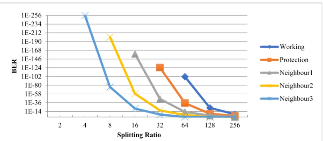
The optical performance is then plotted against its error due to the passive element at the last mile of the GPON FTTH network. An investigation of the failures of the passive elements at the last kilometer of the FTTH network is reported. The number of clusters is thus estimated in the same way as the model's other parameters.
Together with the Dirichlet Process they enable the collection and learning of a number of clusters simultaneously.