This is the primary reason why bio-MEMS is still in the earliest stages of development compared to electrical and mechanical sensor devices and systems. 4 Bio-MEMS: Technologies and Applications biological or biomedical aspects of the materials covered in these chapters.
Main Contents and Organization of the Book
Microfabrication Technologies
Microfluidic Devices and Components for Bio-MEMS
In most bio-MEMS, the sample usually undergoes several sample preparation or pretreatment steps before being submitted to the actual analysis. There are many research reports in the literature detailing the advancement of flow cytometry and a review of the state-of-the-art in this field.
Sensing Technologies and Bio-MEMS Applications
6 Bio-MEMS: Technologies and Applications it is necessary to integrate all the components for sample preparation (including sample extraction, sample preconcentration and sample derivatization), sample introduction, separation and detection on a single microchip made of either glass, silica or polymers. As the dimensions of bio-MEMS element processing are reduced, the basic building blocks of biology such as single cells overview of emerging technologies for single cell and single molecule analysis using microfluidic devices are analyzed and demonstrated.
Suggestions for Using This Book as a Textbook
Introduction
UV Lithography of Ultra-Thick SU-8 13 This chapter will first introduce the recent development of SU-8 lithography of ultra-thick SU-8 resist, followed by a summary of UV lithography conditions and some processing tips. Finally, some applications of UV lithography of ultra-thick SU-8 resist in microfluidics and microoptics will be shown.
Numerical Study of Diffraction Compensation
Diffraction Caused by Air Gap and Wavelength
The absorption coefficient of unexposed SU-8 at 365 nm (where the photoresist is most sensitive) is about 4 times that of the absorption coefficient at 405 nm. Full understanding of the Fresnel diffraction is therefore very important for obtaining a high-quality, ultra-high aspect ratio in UV lithography of thick SU-8 resist.
Numerical Analysis of Diffraction and the Absorption
Numerical simulations were performed to obtain the Fresnel diffraction pattern at the bottom of the resist layer. Measured transmissions for both the i-line and h-line for different thicknesses of SU-8. a) Fresnel diffraction pattern in the bottom of the resist layer as projected by the i-line light source.
![Figure 2.5 shows the simulated sidewall profiles when a 20 µ m–wide slot pattern is exposed using i -line and h -line light sources, respectively [15]](https://thumb-ap.123doks.com/thumbv2/123dok/10290052.0/27.918.244.676.617.940/figure-simulated-sidewall-profiles-pattern-exposed-sources-respectively.webp)
Development with One-Direction Agitation Force
The concentration decreases closer to the boundary between the dissolved and the solid parts of the uncrosslinked SU-8. With the sample face down, the diffusion and removal of the dissolved SU-8 from the boundary region of the developer and the uncrosslinked SU-8 was accelerated by gravity.
Experimental Results Using Filtered Light Source and Air Gap
A 4.538 mm thick PMMA sheet (unannealed) was used as a filter to eliminate the short wavelength components of the Oriel UV station light source. The minimum designed thickness of the crosses achieved is 20 µm for the air gap and 8 µm for the leveling of the glycerine gap.
Basic Steps for UV Lithography of SU-8 and Some
- Pretreat for the Substrate
- Spin-Coating SU-8
- Soft Bake
- Exposure
- Postexposure Bake (PEB)
- Development
The thickness of SU-8 films depends on several factors: the viscosity of the SU-8 used, the spin speed and the total number of turns. UV lithography of Ultrathick SU-8 29 overheating, scattering and diffusion on the surface of the resist.
Tilted Lithography of SU-8 and Its Application
Micromixer/Reactor
The micromixer/reactor has a simple structure and significantly increases mixing efficiency by increasing interfacial contact with the colliding plumes of two opposing arrays of more, but smaller, micronozzles. By increasing the flow vortices generated and increasing the interfacial contacts, the mixers based on offset arrays of impinging jets have better mixing efficiency.
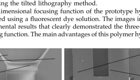
Three-Dimensional Hydrofocus Component
In the center of the end of this sample flow inlet there is a diamond-shaped nozzle with a width of 100 µm. In the fabrication process, all the slopes and the sample injection holes were fabricated using tilted exposure.
Out-of-Plane Polymer Refractive Microlens,
46 Bio-MEMS: Technologies and Applications Weight of irradiated material so that it can be selectively removed in a suitable developer (step 2). 64 Bio-MEMS: Technologies and Applications For most MEMS applications, the sulfamate solution is preferred. The boric acid in the bath serves as a buffer and helps control the pH of the solution.
98 Bio-MEMS: Technologies and Applications The other important process parameter is the initial thickness of the resist [11,15]. SEM micrographs (b) of the NIL stamps used for the fabrication of nanopores and (c) of the corresponding nanopores. However, the interaction of the laser light and the polymer material causes surface modifications compared to the untreated material [29,30].
SEMs of (a) a microchannel array of a flow cytometry system in PC fabricated with a silicon RIE tool, (b) a high aspect ratio test structure embossed in PC using a master fabricated with LIGA and nickel plating, (c) a silicon tool for a two-dimensional channel array for 2D capillary electrophoresis, and (d) the replicated PMMA structure. As fluid flows in a forward direction, most of the fluid flow occurs through the main microchannel. In the absence of turbulent transport, the only way to achieve effective mixing is to reduce the molecular diffusion length.

Introduction
Some Basic Considerations
Increasing the microchannel cross section alleviates the high pressure requirement but increases the device volume. Nevertheless, in the above example, using a 500 µm by 500 µm channel reduces the pressure drop per unit length of channel for the same Reynolds number by two orders of magnitude, but the volume of the channel is increased by a factor of 25. Larger chip volume translates into larger volumes of samples and reagents, negating to some extent the benefit of reducing bioanalytical processes to the micro scale.
In conclusion, turbulent flow on the microscale is beneficial for achieving efficient mixing, but its applicability is limited due to pressure drop and chip volume limitations. However, an overview of representative examples of micromixers from each class will be provided here for the reader's convenience.
Passive Micromixers
Pressure-Driven Passive Micromixers
A two-slice, multi-flow (10) mixer with contraction into a high aspect ratio mixing channel (8) was developed by Floyd et al.22 on a silicon chip using deep reactive ion etching (DRIE). . A Ψ-junction glass micromixer with a very low aspect ratio (0.012) was developed by Holden et al.25 for the simultaneous production of mixtures of quasi-continuously varying concentrations. A passive single-layer micromixer incorporating complex Tesla structures was demonstrated by Hong et al.32 in a cyclo-olefin copolymer (COC), low-aspect-ratio (0.45) microchannel fed by a T-junction.
An effective micromixer with staggered cylindrical obstacles in a mixing chamber was demonstrated by Lin et al.41 on a silicon chip that generates fluid streams with high Reynolds numbers (approximately 380). Recently, Lin et al.44 simulated and demonstrated a multi-inlet swirl chamber micromixer with performance at low Reynolds numbers (less than 20), realized in a multilayer silicon chip.
Electrically Driven Passive Micromixers
A variety of chamber-based electro-osmotic mixers were proposed by Yager et al.47, based on recirculations generated by pressure gradients imposed by the conservation of mass. Thus, a recirculating flow will be established within the mixing channel with shear layers in the vicinity of the walls. The velocity near the wall is higher in the upper half compared to the lower half, and as a result the return velocity is higher in the lower part of the core.
Another numerical study by Hong et al.53 demonstrated improved mixing using corner and herringbone models. 188 Bio-MEMS: Technologies and Applications Inhomogeneous surface charge distributions based on grooved channel configurations used by Stroock et al.36 in a homogeneous pressure-driven flow.
Active Micromixers
A similar device, with a cross-junction and without integrated pumping, was presented by Lee et al.61 and was also fabricated in silicon using DRIE. A swirl chamber mixer micromilled in PMMA was proposed by Chung et al.9, where the swirling of the liquids was achieved by forward and backward pumping. Soon after, Oddy et al.68 presented electric active mixers based on electrokinetic instability excited by sinusoidal oscillations of the electric file.
They evaluated a glass-coated PDMS cross-junction mixer and a chamber cross-junction very similar to that of Lee et al.61 in Borofloat glass. More recently, Shin et al.72 performed an experimental study of an electrically actuated and actuated cross-junction, microchannel mixer realized on glass.
Multiphase Micromixers
Very good performance in mixing using magnetic microbeads was achieved by Rida et al.76 in a micromix realized in polymethyl methacrylate (PMMA) with integrated ferromagnetic permalloy layers to focus the magnetic field created by an external electromagnet. In a rather rare design involving moving parts, Lu et al.77 and Ryu et al.78 developed micromixer chips with PDMS or Parylene Ψ-junction microchannels with an integrated alloy rod rotor on a silicon substrate. 192 Bio-MEMS: Technologies and Applications The same principles of electrowetting were used in a more recent experimental study by Paik et al.,84 which illustrated flow patterns and enhanced mixing within millimeter-sized droplets and used a liq. unmixed (silicone oil) rather than a gas buffer between the drops.
The manipulation of small volume fluids and enhanced mixing using electric field phenomena is limited to polarizable or conducting fluids. For a review and theoretical aspects of this still nascent approach, we refer the reader to Darhuber et al.85.
Performance Metrics for Microscale Mixer Design
In such cases, these mixers will produce a mixed product at different rates depending on the concentration distribution relative to the velocity distribution. When an appropriate definition of mixing efficiency is used and given the specific requirements for its value, mixing time (which is also appropriately defined for the application as mentioned earlier), pressure drop, and device volume are important performance metrics for a microscope mixer. The pressure drop combined with the volumetric flow rate of the fluid in the device is reflected in the magnitude of the power required to drive the flow in the device and is specific to pressure-driven microfluidic chips.
In the laminar microfluidic medium, the pressure drop across a microchannel is a linear function of the volumetric flow rate, and thus the power requirement is generally quadratic with the flow rate. Few would argue that a microchannel-based, diffusion-driven mixer is one of the simplest.
Design Methodology for Optimal Diffusion-Based, Micromixers
The latter is important because micromixers are more likely to be needed as an integral part of a microfluidic biochip whose primary function is not mixing, and should be designed with this in mind. Some of these practically important attributes understandably tend to be overlooked in individual scholarly articles in terms of detailed and comparative evaluation. In the next section, an easy procedure to design and optimize such a mixer with batch production specifically in mind will be given.
Although a pressure driven mixer will be considered, extension to an electroosmotic motor mixer can easily be made. A somewhat more general case will be considered involving multiple layers of fluids to be mixed and an evaluation of the impact of design parameters on performance will be made.
![Figure 5.11 shows SEM images of a grid pattern of approximately 150 nm- nm-wide trenches spaced at 1 µm [56]](https://thumb-ap.123doks.com/thumbv2/123dok/10290052.0/140.918.221.689.202.462/figure-shows-sem-images-pattern-approximately-trenches-spaced.webp)