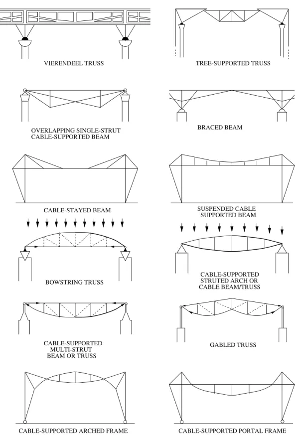
They are usually cable-supported and are used for tents and long-span roofs Fig Shells: 3D structures composed of a curved 2D surface, they are usually shaped to transmit compressive axial stresses only, Fig.
Structural Engineering Courses
But they can also be used as Stacked panels are mainly used as long-span roofs. Draft1.12 References 27fer mechanism for most types of structures, cables, arches, supports, frames, shells, plates.
Engineers: The focus is on individual structural elements and not always on the entire system.
LOADS
- Introduction
- Vertical Loads
- Lateral Loads
- Other Loads
- Other Important Considerations
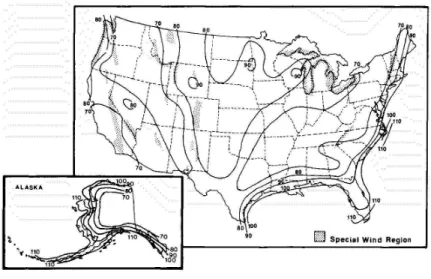
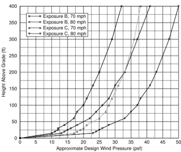
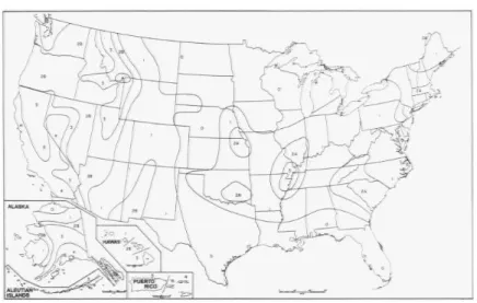
29 This size must be adjusted to take into account the shape and surroundings of the building. This is responsible for the fact that wind speed increases with height and that dynamic character of the air flow (i.e. the wind pressure is not constant), Table2.6.
STRUCTURAL MATERIALS
Steel
Steel 59
- Aluminum
- Masonry
- Timber
- Steel Section Properties
16 Steel is also used as wire and rope for suspended roofs, cable-stayed bridges, fabric roofs and other structural applications. 1Braces used as vertical reinforcement to resist shear usually have a yield stress of only 40 ksi.
Joists 73
- Joists
Joists 75
- Materials, & Geometry
Loads 79
- Loads
- Reactions
- Trusses
- Theory
Some of the same problems will be revisited later for determining internal forces and/or deflections. Due to symmetry, we will only consider the dead load on one side of the frame. Depending on the orientation of the diagonals, they can be either under tension or compression.
7Therefore, the sign convention for design moments in most European countries is the opposite of the one commonly used in the U.S. used; Reinforcement should be placed where the moment is "postive". 65 So far we have considered the kinematics of the beam, but later we will have to consider equilibrium in terms of the stresses. Example 5-11: Approximate analysis of a statically indeterminate beam Perform an approximate analysis of the following beam, and compare your results with the exact solution.
Theory 125
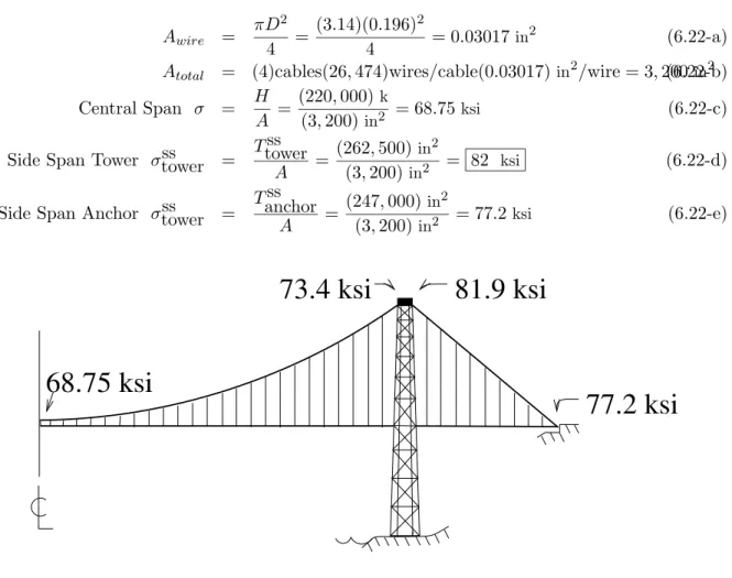
- ksi81.9 ksi
- ksi 68.75 ksi
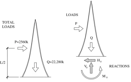
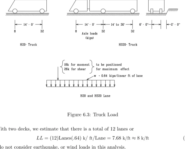
Because of our assumption of pulley support for the cables, the towers will only be subject to axial forces. 16 The dead load consists of the weight of the deck and cables and is estimated at 390 and 400 psf for the center and side spans, respectively. The HS-20 truck is often used for the design of bridges on major highways, Fig.
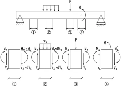
Either a structural truck with specified axle loads and spacing or an equivalent uniform load and concentrated load must be used. 22 The vertical force in the columns due to the center span (cs) is simply the support reaction, 6.6. This is often idealized as a beam on elastic foundations, and the resulting shear and moment diagrams for this idealization are shown in Fig.
A BRIEF HISTORY OF
STRUCTURAL ARCHITECTURE
- Before the Greeks
- Greeks
- Romans
- The pre-Modern Period; Coulomb and Navier
- Geometry
- Loads
- Reactions
- Forces
- Forces 161
- Safety Provisions
- Ultimate Strength Method
- Example
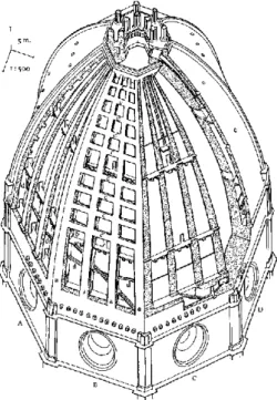
Its form was determined by its structural needs, one of the first examples of architectural functionalism. He also showed that the curvature at any point along a beam is proportional to the curvature of the deflection curve. 90 John Augustus Roebling was an American civil engineer, who was one of the pioneers in the construction of suspension bridges.
4 The load on the frame is the result of the weight of the roof panel and the frame itself. 9 The axial force at the end of the beam is not balanced and compression 88 kip must be transferred to the lower chord, fig. Variability of material strength (greater variability of concrete strength than steel strength).

BRACED ROLLED STEEL BEAMS
COMPOSITE BEAM B) OTHER FRAMING
CROSS BRACING
- Slender Section
- Examples
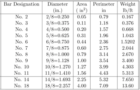
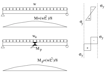
13 When the yield stress is reached at the extreme fiber, the nominal moment strength Mn is called the yield moment My and is calculated as. assuming bending occurs with respect to the x-x axis). 14 If the strain over the entire cross-section is equal to or greater than the yield strain (ε≥εy = Fy/Es), then the cross-section is completely plasticized and the nominal moment strength Mn is therefore called the plastic momentMp and determined from. 15 The plastic section modulus Z should not be confused with the defined elastic section modulus S, Eq.
16 Section modulus Sx of section W can be approximately approximated by the following formula Sx≈wd/10 or Ix ≈Sxd. 23 If the width-thickness ratio exceeds the λr values of the flange and rib, the element is called a thin compression element. Assuming that the section is compact, as the vast majority of rolled sections satisfy λ≤λp for both the flange and the strip.
REINFORCED CONCRETE BEAMS
Introduction
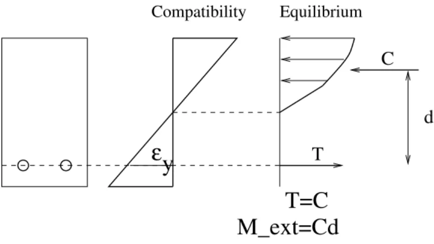
Design: Given an external moment to be resisted, determine cross-sectional dimensions (band h) as well as reinforcement (As). Note that in many cases the external dimensions of the beam (b and h) are determined by the architect. Material stress strain: We recall that all normal strength concrete has a fracture strain u=.003 in compression, regardless of fc0.
Note that these two materials also have very close coefficients of thermal expansion at normal temperature. However, if such a section exists, and we need to determine its moment-carrying capacity, then we have two unknowns: Stress compatibility: since we know that at failure the maximum compressive stress εc is equal to 0.003.
Continuous Beams
ACI Code
10.2.2 - Deformation in reinforcement and concrete shall be assumed directly proportional to the distance from the neutral axis, except for deep bending members with overall depth to free span ratios greater than 2/5 for continuous spans and 4/5 for simple spans, a non-linear distribution of strain will be considered. 10.2.4- Stress in reinforcement below the specified yield strength for grade of reinforcement used shall be taken as Es times steel strain. 10.2.5- Tensile strength of concrete shall be neglected in flexural calculations of reinforced concrete, except when requirements of Section 18.4 are met.
10.2.7.1- Concrete stress of 0.85fc0 must be assumed uniformly distributed over an equivalent compression zone delimited by edges of the cross-section and a straight line placed parallel to the neutral axis at a distance (a=β1c) from the fiber of maximum compressive load. 10.2.7.2 - Distance c from fiber with maximum strain to the neutral axis must be measured in a direction perpendicular to this axis. 10.3.4 - Compression reinforcement in conjunction with additional tensile reinforcement can be used to increase the strength of flexural members.
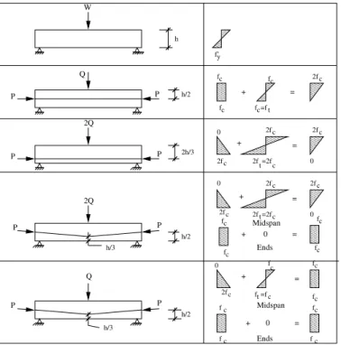
PRESTRESSED CONCRETE
Introduction
Q RRRRR RRRRR RRRRR RRRRR RRRRR RRRRR RRRRR RRRRR RRRRR RRRRR SSSSS SSSSS SSSSS SSSSS SSSSS SSSSS SSSSS SSSSS SSSSS SSSSS. U VVVVV VVVVV VVVVV VVVVV VVVVV VVVVV VVVVV VVVVV VVVVV VVVVV WWWWW WWWWW WWWWW WWWWW WWWWW WWWWW WWWWW WWWW WWWWW WWWWW. 10 Steel relaxation is the reduction in stress at constant stress (as opposed to creep, which is a reduction in stress at constant stress).
Note that ftscan only reaches 12pfc0 if proper deflection analysis is done because the section will crack. 30 The live load is generated by traffic and is estimated to be 94 psf, so over a width of 62.5 feet this gives a uniform live load. 2 The concepts used are identical to those seen previously, however the main (and only) difference is that the equations will be written in polar coordinates.
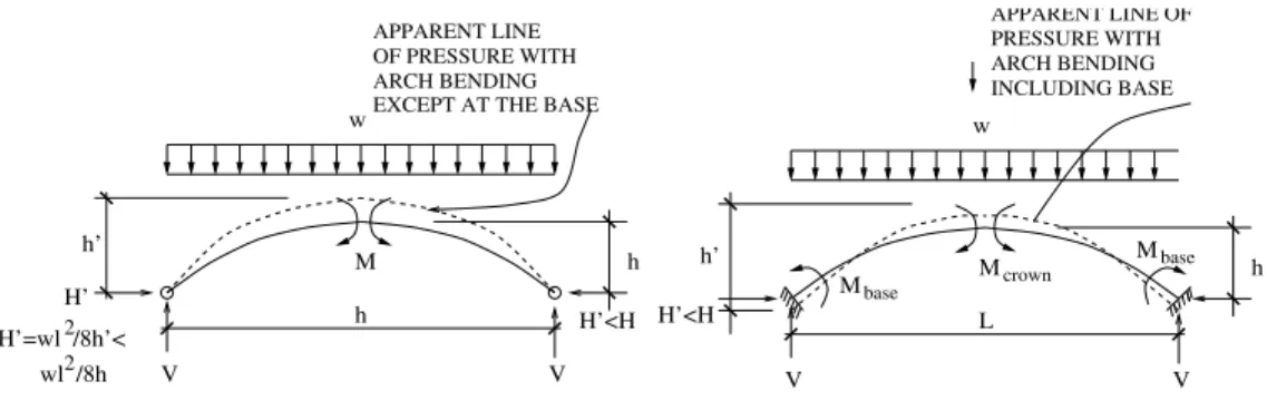
Arches
First, the depth (and thus the weight) of an arch is usually not constant, so the actual self-weight due to the slope of the arch is not constant. Determine the reactions of the three hinged statically determined semicircular arches under its own dead weight w(per unit arc length s, where = rdθ). The virtual force δP will be a vertical unit point in the direction of the desired deflection, causing a virtual internal moment.
Determine the value of the horizontal reaction component of the indicated two-hinged solid rib arch, fig. 13.8, as caused by a concentrated vertical load of 10 k at the center line of the span. A unit fictitious horizontal force is applied at C. The axial and shear components of this fictitious force and of the vertical reaction at C acting on any section θ in the right half of the rib are shown at the right end of the rib in Fig. Victor Saouma structural concepts and systems for architects. For the given rib and the single concentrated load at mid-span, it is obvious that the effects of shear and axial stresses are negligible and can be neglected.
BUILDING STRUCTURES
Introduction
Buildings Structures
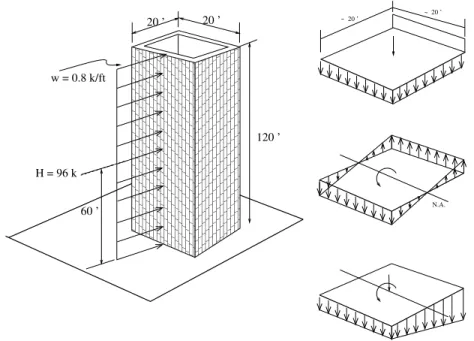
This amount of reinforcement should be provided at both ends of the wall, as the wind or earthquake can act in all directions. The design could be modified to not have tensile forces in the columns by increasing the width of the base (currently at 20 feet). Draft 14.3 Approximate Analysis of Buildings 241 Column displacement Inflection points are mid-height, with possible exception when the columns. on the first floor, the hinge is at the bottom, Fig.
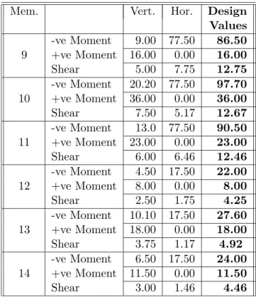
The total horizontal shear at mid-height of all columns at any floor level will be distributed among those columns so that each of the two exterior columns carries half as much horizontal shear as each interior column of the frame. Column shear is obtained by passing a horizontal section through the mid-height of the columns at each floor and summing the lateral forces above it, then Fig. Design parameters Based on two approximate analyses, vertical and lateral load, we now look for design parameters for the frame, Table 14.2.
Lateral Deflections
43 Deflection of a rigid frame is mainly caused by shear between floors, causing vertical shear in the beams. The deflection due to moment increases rapidly at the top, the value of 1/1,800 only indicates the average drift index for the entire building, while the floor drift index can be higher, especially for the top floor. Because the story deviation varies with the shear in the floor, which decreases linearly toward the top, the average deviation will be ft per floor and the deflection at the top of the building is approximately.
Furthermore, the frame would not be stiff enough to carry all the lateral load itself. Keeping the lateral load in proportion to the relative stiffnesses, the frame will carry about 1/6 of the load, and the remaining 5/6 will be carried by the axle. Increasing the column size will stiffen the frame, but to be truly effective, the beam stiffness will also need to be increased, as the girders contribute about 2/3 of the Victor Saouma Structural Concepts and Systems for Architects.