Specification and parameter may vary. Please enquire our company or any group’s subsidiary whenever want to use it.
Content of catalogue is as on January 2017.
Version 2017 vol. 1
Seismic Isolation Product Line-up
High Damping Rubber Bearing Lead Rubber Bearing Natural Rubber Bearing Elastic Sliding Bearing
Bridgestone Corporation
Seicmic Isolation & Vibration Control Products Business Department Yaesu Center Bldg. 11F, Yaesu, Chuo-ku, Tokyo 103-0028, Japan TEL : +81-3-5205-6865 FAX: +81-3-5202-6848
EMAIL : [email protected]
URL : http://www.bridgestone.com/products/diversified/antiseismic_rubber/index.html MORE INFORMATION ON SEISMIC http://www.menshin-channel.com/index.html
Bridgestone Engineered Products of Asia Sdn Bhd Bridgestone Engineered Products of Asia Sdn Bhd (Australia) L1-E-3B, Enterprise 4, Technology Park Malaysia, Unit 17/27 Old Great Northen highway,
Lebuhraya Puchong-Sg. Besi, Bukit Jalil, Midland WA 6056,
57000 Kuala Lumpur, Malaysia. P.O Box 2325 Midland WA 6936
TEL: +60-3-8996-2670 FAX: +60-3-8996-2690 TEL: +61-8-9250-0600 FAX: +61-8-9250-0601
EMAIL: [email protected] EMAIL: [email protected]
PT. Bridgestone Mining Solutions Indonesia Bridgestone Engineered Products of Asia Sdn Bhd (India) Wisma Nusantara Building 12th floor, Office No. 404, 4th Floor, Time Tower,
Jl. M.H. Thamrin No. 59, Jakarta 10350, Indonesia Mehrauli Gurgaon Road, TEL: +62-21-3190-8077 FAX: +62-21-3983-5881 Gurgaon-122001, India
TEL: +91-124-4262321/+91-124-426232 EMAIL: [email protected]
Bridgestone Diversified Products Japan Co., Ltd. BRISA Bridgestone Sabanci Tyre Manufacturing and
Taiwan branch Trading Inc (Turkey)
6F-2, No.41, Kısıklı Cad. Şehit Teğmen İsmail Moray Sok.,
Nanking W.Rd, No:2/1, 34662 Altunizade,
Taipei, Taiwan, R.O.C Istanbul, Turkey
TEL: +886-2-2556-3459 FAX: +886-2-2556-3487 TEL: +90-216-544-3500/2192 FAX: +90-216-544-3535
High Damping HDR
Rubber Bearing
Lead Rubber Bearing LRB
Natural Rubber Bearing NRB
Elastic Sliding Bearing
High damping rubber includes both spring and damping characteristics. Generally, a separate damper is not required, making it an excellent choice for areas with space constraints. Since its hysteresis curves are relatively smooth, seismic isolation can also be extended to the equipment inside the building.There are 3 different elastic moduli are available (X0.3R, X0.4S, X0.6R). From light column loads until high rise building can be accommodated.
This bearing includes a lead plug embedded at the centre of a laminated natural rubber structure, where the rubber incorporates the spring capability and the lead plug provides the damping capability. Generally, a separate damper is not required making it a good choice for areas with space constraints. Its hysteresis resembles elasto- plastic materials. The attenuation can be tuned by varying the lead plug diameter. One type of rubber material is available (G0.40).
This bearing uses natural rubber, which inherently has a low damping ratio (about 2~3% equivalent damping ratio), excellent linearity, and a stable restoring force.
A separate damper is required, but the overall isolation design has much greater flexibility. Four different kinds of elastic moduli are available ( G0.30 , G0.35 , G0.40 , G0.45 ) to support a wide range of column loads.
This bearing consists of 2 pieces: 1) a natural rubber bearing bonded with PTFE (Teflon) material and; 2) a stainless steel slide plate.
Small displacements are absorbed by the rubber itself, while large displacements cause the rubber bearing to slide on the plate. Since there is no restoring force, the slide bearing is normally used in combination with NRB, LRB or HDR. Two different coefficients of friction are available to suit the damping requirements.
Features Sectional View
Bridgestone Seismic Isolation Product Line-up
We will meet the customer needs with our new product line-up
Note: The above diagram and hysteretic loop are for illustrative purpose only.
High Damping Rubber Reinforcing Steel Plate
Cover Rubber
Flange
Lead Plug Natural Rubber Reinforcing Steel Plate
Cover Rubber
Flange
Natural Rubber Reinforcing Steel Plate
Cover Rubber
Flange
Flange
Sliding material
(PTFE) Sliding Plate
(SUS or SUS+PTFE Coating)
Hysteretic Loop Content
Bridgestone Seismic Isolation product line up ... 1
HDR LRB NRB Elastic Sliding Bearing Introduction of Product & System ... 3
High Damping Rubber Bearing X Series ... 3
Layout Planning Assistance Program ... 5
Product Specification & Performance Characteristic ... 6
High Damping Rubber Bearing (HDR) ... 6
Lead Rubber Bearing (LRB) ... 9
Natural Rubber Bearing (NRB) ... 11
Elastic Sliding Bearing ... 13
Product Specification ... 15
High Damping Rubber Bearing (HDR) ... 15
Certification Number MVBR-0516 (X0.3R) Certification Number MVBR-0510/MVBR-0519 (X0.4S) Certification NumberMVBR-0514/MVBR-0520 (X0.6R) HM Series (Total Rubber Thickness 16cm) ... 15
HN Series (Total Rubber Thickness 20cm) ... 16
HH Series (Total Rubber Thickness 20cm) ... 17
HL Series (Total Rubber Thickness 16cm) ... 19
HT Series (Total Rubber Thickness 25cm) ... 21
HS Series (S
2= 5) ... 23
HD Series (Total Rubber Thickness 32cm) ... 24
Lead Rubber Bearing (LRB) ... 25
Certification Number MVBR-0517 Lead Plug Diameter List ... 25
LH Series (Total Rubber Thickness 20cm) ... 27
LL Series (Total Rubber Thickness 16cm) ... 36
LT Series (Total Rubber Thickness 25cm) ... 43
LD Series (Total Rubber Thickness 32cm) ... 50
LS Series (S
2= 5) ... 53
Natural Rubber Bearing (NRB) ... 62
Certification Number MVBR-0295 (N3,G3,G5) Certification Number MVBR-0509/MVBR-0518 (G4) NS Series (S
2= 5) ... 62
NH Series (Total Rubber Thickness 20cm) ... 66
NL Series (Total Rubber Thickness 16cm) ... 67
NT Series (Total Rubber Thickness 25cm) ... 68
ND Series (Total Rubber Thickness 32cm) ... 69
Elastic Sliding Bearing ... 70
Certification Number MVBR-0349 SL Series ( = 0.13 & G1.2) ... 70
Others ... 71
Compact Flange ... 71
Dustproof Cover ... 72
Precautions for Safe Use of Seismically Isolated Bearing... 73
X4S Series:γ=±50,100,200,300%
X6R Series:γ=±100,250%
SL Series
Features of High Damping Rubber Bearing X Series
High damping rubber bearing is a laminated rubber structure that includes a special filler compound in the rubber itself to provide energy absorption performance. It combines damping and spring charateristics and is widely adopted as a seismic isolator.
However, the conventional high damping rubber shows loading hysteresis dependency, where its rate of change of stiffness has become reduced and restoration becomes progressively worse after repeated loading under increasing deformation.
With Bridgestone’s next-generation of high damping rubber X series, the effect of loading hysteresis dependency is greatly reduced and the properties become much simpler to manage. Furthermore, it is also more accommodating to the reduction in ultimate properties caused by bi-directional loading.
Reduction in Loading Hysteresis Dependency
Compared to conventional high damping rubber, the change of equivalent shear stiffness (1cycle/3cycle) in repeated loading is greatly reduced. The properties of seismic isolation bearings are defined by the 3rd cycle and it is able to reduce the load variation during initial deformation.
Conventional high damping rubber shows shear stress reduction after large deformation due to the effect of loading hysteresis dependency, but the next-generation high damping rubber is able to minimize the change in properties before and after large deformation. By reducing the effect of loading hysteresis dependency, the accuracy of the overall seismic isolation design can be improved.
Increasing of Equivalent Damping Ratio
Compared to conventional high damping rubber, the equivalent damping ratio (at shear strain = 100%) of high damping rubber X0.4S, X0.6R are increased (X0.4S:0.220 → 0.240, X0.6R:0.225 → 0.240). Furthermore, compared to the same diameter of lead rubber bearing (lead diameter/outer diameter = 0.2), a higher damping ratio can be obtained in the range of 130%.
High Damping Rubber Bearing X Series
Product & System Introduction
2.0
0 0.5 1 1.5
− 1
− 0.5
− 1.5
− 2
− 3 − 2 − 1 1
Shear strain Shear stress (N/mm2)
3
0 2
2.0
0 0.5 1 1.5
− 1
− 0.5
− 1.5
− 2
− 3 − 2 − 1 0 1 2 3
Pre test Post test
E0.6 Conventional material E0.6
Shear strain Shear stress (N/mm2)
X0.6R Pre test
Post test
1.3 time 1.15 time
New material X0.6R
Shear strain Equivalent damping ratio Heq (−)
0.00 0.10 0.20 0.30 0.40
0.0 1.0 2.0 3.0
Lead rubber bearing HDR X0.6R HDR X0.4S 2.0
1.6
0.8 1.2
0.4
0
0 0.5 1 2
Shear strain Shear stress (N/mm2)
3
1.5 2.5
Pre test Post test Conventional material E0.6
2.0 1.6
0.8 1.2
0.4
0
0 0.5 1 2
Shear strain Shear stress (N/mm2)
3
1.5 2.5
Pre test Post test New material X0.6R
Ultimate Properties of High Damping Rubber Bearings by Horizontal Bi-directional Loading
Outline
The ultimate deformation of high-damping rubber is degraded by applying bi-directional loading compared to unidirectional loading. Through a horizontal bi-directional loading test with a full scale model high-damping rubber bearing, torsional deformation can be seen in the side view of the rubber. Compared with unidirectional loading, the phenomenon of breaking at early stage by bi-directional loading has been identified. The standard value of the ultimate properties, influenced by bi-directional loading is shown below and the ultimate compressive stress is confirmed.
As shown in Figure 1, when the bi-directional loading is applied on a high damping rubber bearing, the elastic force occurs in the shear deformation direction, while the damping force occurs in the tangential direction of the deformation trajectory. The torsional moment created by the damping elements and the shear deformation is present at each rubber layer of the laminated structure. The additional shear strain
caused by torsional deformation is added to the shear strain caused by the rubber shear deformation itself. Thus, it will rupture relatively early compared to the unidirectional loading test. However, the torsional deformation caused by bi-directional loading does not affect the buckling ultimate strain, as verified experimentally.
Ultimate Property of Horizontal Bi-directional Loading
According to the Japan Society of Seismic Isolation (JSSI) guidelines, the final ultimate strain is determined by the minimum of the ultimate strain
Lby unidirectional loading and the ultimate strain
Boby bi-directional loading.
Ultimate strain by unidirectional loading
Ultimate strain by unidirectional loading is defined as shown in Table 1.
Table 1: Standard value of ultimate strain by unidirectional loading Compound Ultimate strain by unidirectional loading
LXO.4S S
2× 0.9 × 100% (0.9 × S
2< 4) 400% (0.9 × S
2 4) XO.6R S
2× 0.9 × 100% (S
2< 4.5)
400% (S
2 4.5) S
2: Second shape factor
Ultimate strain by bi-directional loading
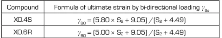
Ultimate strain by bi-directional loading is defined as shown in Table 2.
Table 2: Standard value of ultimate strain by bi-directional loading Compound Formula of ultimate strain by bi-directional loading
BoXO.4S
B0= (5.80 × S
2+ 9.05) /(S
2+ 4.49) XO.6R
B0= (5.00 × S
2+ 9.05) /(S
2+ 4.49) S
2: Second shape factor
Damping element
∆u
③ u2
②
① Elastic element Fn
Dashed line : Bottom flange (Loading side)
Solid line : Top flange (Fixed side)
X Y
u1
MT = ( | u2 | × Fn) /2
40 50
30 S2=4.55
20
10
00 1 2
Shear strain Compressive stress (N/mm2)
3 4 5
60 S2=5.0
30
00 1 2
Shear strain Compressive stress (N/mm2)
3 4 5
X0.4S (Bi-directional) X0.4S (Unidirectional)
X0.6R (Bi-directional) X0.6R (Unidirectional)
Figure 1: The mechanism of torsional deformation
Figure 2: Torsional deformation during horizontal bi-directional loading
Figure 3: Comparison example of ultimate
property diagram
LAP
2+ t.Ver2 is a program that supports layout planning of Bridgestone seismic isolation bearing for seismically isolated building.
The ideal seismic isolation bearing (in terms of size) can be determined from the column axial force (nominal long term column load) and the selections of sesimic isolation bearing’s series based on the layout of the seismic isolation interface. In addition to Bridgestone made seismic isolation bearings, hysteresis type dampers or oil dampers which are typically used in Japan can be specified in the program.
The selections can be changed (or specified) interactively on the GUI (Graphic User Interface) screen by the click of a mouse and the notification calculation for that bearing arrangement can be carried out as well.
Besides, regarding to the bearing layout planning, the mathematical process which is using genetic algorithm could produce an optimization function whereby by satisfying the notification calculation and at the same time reduce as much as possible the shear force for the layout plan,or by satisfying the notification calculation and at the same time reduce as much as possible the response displacement for the layout plan that could meet the criterias. In addition to being able to verify by the notification calculation, the Lap
2+ t.Ver2 software allows response calculation for seismic response analysis.
Simple Input Seismic Isolation Devices
From the data-input and modification of the seismic isolation interface, seismic response analysis can be conducted easily. Also, Lap
2+ t.Ver2 is compatible software that can capture or transfer structural calculation data from the “Super Build / SS3” software which is developed by Union System.
”Super Build / SS3” is a registered trademark of Union System Inc.
Bridgestone natural rubber bearing, lead rubber bearing, high damping rubber bearing, elastic sliding bearing, other standard hysteretic dampers and oil dampers can be adopted.
2 Calculation Functions of Seismically Isolated
Structure Layout Planning of Seismic
Isolation Devices
“Seismic Response calculation by seismic isolation notification∗1 “……the results of the calculation can be printed in a reporting style.
“Seismic response calculation by time history analysis”……the calculation can be conducted for various earthquake waves. Also, Lap
2+ t.Ver2 can work together with the structural calculation software “Super Dynamic Pro” from Union System.
1 The structural calculation method is based on the “Technical standards required for safety which relates to the structural method for seismically-isolated buildings” as stated in the notification No.2009 of the Ministry of Construction, in the year 2000.
The software helps you to choose the appropriate seismic isolation devices and its placement in the building to satisfy the target performance.
LAP
2+ t.Ver2 (Layout Planning Assistance Program for Seismic Isolation Device)
Bearing selection Column coordinates, axial force, bearing type,
building characteristics
Seismic response analysis Product DB
M
K,h Target
performance achieved
No
Yes Bearing selection
is finalized and finished.
Seismic isolation material certification number by Ministry of Land, Infrastructure and Transport, Japan
MVBR-0516 (X0.3R Series) Acquired in December 2014
MVBR-0510/MVBR-0519 (X0.4S Series) Acquired in December 2014 MVBR-0514/MVBR-0520 (X0.6R Series) Acquired in December 2014
Product Dimension
Characteristics Sectional View
Physical Dimensions
Outer diameter : Do (mm)
Inner diameter : Di (mm)
Number of inner diameter : ni
Effective plane area : A ( × 102mm2) Thickness of one rubber layer : tr (mm)
Number of rubber layers : n
Total rubber thickness : H = n tr (mm) First shape factor S1 = (Do2 - ni Di2) / {4 tr (Do+ni Di)}
Second shape factor S2 = Do / (n tr)
Diameter of flange : Df (mm)
Thickness of flange: edge/center : tf / tft (mm)
Connecting bolt PCD : PCD (mm)
Diameter of connecting bolt hole × qty : db (mm) × qty Bolt size (assumption) : M (db −3) Thickness of each reinforced steel plate : ts (mm)
Total height : Ht (mm)
Total weight 1 (kN) = 1 / 9.80665 (tonf)
Rubber Material
Notation of rubber kind (standard temperature 20°C standard strain = 100%) Composition of rubber materials (weight ratio %) Compound
name Rubber code Shear modulus
Geq (N/mm2) Equivalent damping
ratio Heq Rubber code Natural rubber
Synthetic rubber Filler, Reinforcement
agent Vulcanization agent and others
X3R X0.3R 0.300 0.17
Inner Rubber
X0.3R 35 and above 15 and above 50 and below
X4S X0.4S 0.392 0.24 X0.4S 35 and above 20 and above 45 and below
X6R X0.6R 0.620 0.24 X0.6R 35 and above 25 and above 40 and below
Properties of rubber materials Cover rubber 40 and above 15 and above 40 and below
Item Tensile strength
(N/mm2) Elongation at
Break (%) Hardness
(JIS A) 100% modulus
(N/mm2) Young's modulus
E (N/mm2) Bulk modulus
E∞(N/mm2) Correction factor for apparent Young's modulus according to hardness, k
Test Standard JIS K6251 JIS K6251 JIS K6253 JIS K6251 − − −
Inner Rubber
X0.3R 7 and above 700 and above 34 ± 8 0.53 ± 0.2 4.0 1150 1.0
X0.4S 7 and above 840 and above 37 ± 8 0.43 ± 0.2 6.2 1300 1.0
X0.6R 8.5 and above 780 and above 53 ± 5 0.73 ± 0.2 7.6 1500 1.0
Cover rubber 12 and above 600 and above − −
Steel Material
Steel material for each part Anti-rust treatment of flange
Material Preparation Remove rust up to blasting quality of SSPC-SP-10 (SIS Sa 2 1/2) Reinforced steel plate SS400 (JIS G 3101) Primer Zinc-rich paint 75m × 1 coat
Flange*1*2 SS400 (JIS G 3101) Middle coat Epoxy resin paint 60m × 1 coat Connecting plate*1 SS400 (JIS G 3101) Finishing Epoxy resin paint 35m × 1 coat
*1: Optionally SM490A (JIS G 3106).
*2: Optionally special thickness other than standard thickness. Total film thickness 170m and above
*1: Standard color is gray.
*2: Other kinds of anti-rust treatment are also available. Please contact us for more details.
Precautions
For mid-storey isolation, fire resistant cover is necessary (according to JSSI provision, HS110X4S cannot apply any fire resistant cover).
Please contact fire resistant cover manufacturer who are listed in the JSSI manufacturer list for more details. (http://www.jssi.or.jp/
bussiness/kigyou_detail/to-si-base.htm)
There are two certification numbers for X0.4S, X0.6R due to difference of some manufacturing process. Although their properties values are the same, please fill the certification number as shown in the table on the right in the design documents.
High Damping Rubber Bearing (HDR)
Product Specification & Description of Performance Characteristics
Rubber size 1000 and below Rubber size 1100 and above X0.4S Both MVBR-0510/MVBR-0519 MVBR-0510 only X0.6R Both MVBR-0514/MVBR-0520 MVBR-0514 only
Integrated Type Flange
Assembled Type Flange
Equivalent shear stiffness K
eq, equivalent damping ratio H
eq, initial stiffness K
1, post-yield stiffness K
2, characteristic strength Q
d, Function giving ratio of characteristic strength to maximum shear force of a loop u
Shear properties of HDR is dependent on shear strain amplitude. The shear strain dependency of each property is expressed by the following equations.
Rubber material X0.3R Geq() = 0.0255 4 − 0.2213 3 + 0.7283 2 − 1.1028 + 0.8703 (0.1 3.0) Heq() = − 0.005 3 + 0.015 2 − 0.006 + 0.166
u() = − 0.0087 3 + 0.0262 2 − 0.0105 + 0.2720
Rubber material X0.4S Geq() = 0.054 4 − 0.416 3 + 1.192 2 − 1.583 + 1.145 (0.1 2.7) Heq() = − 0.007 3 + 0.020 2 − 0.009 + 0.236
u() = − 0.0132 3 + 0.0401 2 − 0.0190 + 0.4001
Rubber material X0.6R Geq() = 0.620 × (0.1364 4 − 1.016 3 + 2.903 2 − 3.878 + 2.855) (0.1 2.7) Heq() = 0.240 × (0.02902 3 − 0.1804 2 + 0.2364 + 0.9150 )
u() = 0.408 × (0.03421 3 − 0.2083 2 + 0.2711 + 0.9028 )
Based on above equations, each shear properties shall be determined by the following equations.
*1Equivalent shear stiffness : Keq = Geq A/H Equivalent damping ratio : Heq = W/ (2 π Keq δ2) Initial stiffness : K1 = 10 × K2
Post-yield stiffness : K2 = Keq (1− u) Characteristic strength : Qd = u Keq H
*1: At standard condition only and shall be excluded when considering the properties variation.
Temperature dependency
Each shear properties shall be corrected to the value at standard temperature of 20°C by the following equations.
(Applicable range: −10 T 40°C) (T : Temperature during inspection)
Rubber material X0.3R : Keq (T°C) = Keq (standard value at 20°C) × (1.139 − 9.653 × 10⁻³ T + 1.721 × 10⁻⁴ T2 − 1.847 × 10⁻⁶ T3) : Heq (T°C) = Heq (standard value at 20°C) × (1.050 − 2.790 × 10⁻³ T + 4.678 × 10⁻⁵ T2 − 1.613 × 10⁻⁶ T3)
Rubber material X0.4S/X0.6R : Keq (T°C) = Keq (standard value at 20°C) × (1.205 − 1.862 × 10⁻² T + 5.991 × 10⁻⁴ T2 − 8.991 × 10⁻⁶ T3) : Heq (T°C) = Heq (standard value at 20°C) × (1.065 − 4.134 × 10⁻³ T + 1.096 × 10⁻⁴ T2 − 3.102 × 10⁻⁶ T3)
Standard value of temperature dependency (Standard temperature (20°C))
Properties values Equivalent shear stiffness Keq Equivalent damping ratio Heq
−10°C 0°C 30°C 40°C -10°C 0°C 30°C 40°C
X0.3R within +25% within +14% within −5% within −9% within +8% within +5% within −4% within −9%
X0.4S within +46% within +21% within −6% within −16% within +12% within +7% within −4% within −12%
X0.6R within +46% within +21% within −6% within −16% within +12% within +7% within −5% within −13%
Performance variation
The rate of change of main causes (manufacturing variation, aging, temperature change) which affect shear properties as shown below.
Rubber materials X0.3R X0.4S X0.6R
Equivalent shear stiffness, Keq
Equivalent damping ratio, Heq Function giving ratio of characteristic strength to maximum shear force, u
Equivalent shear stiffness, Keq
Equivalent damping ratio, Heq Function giving ratio of characteristic strength to maximum shear force, u
Equivalent shear stiffness, Keq
Equivalent damping ratio, Heq Function giving ratio of characteristic strength to maximum shear force, u
Manufacturing variation*1 10% 10% 10% 10% 10% 10%
Aging*2 +10% −10% +10% −10% +10% −10%
Ambient temperature
variation 20°C 20°C (+) side +14% +5% +21% +7% +21% +7%
(−) side −9% −9% −16% −12% −16% −13%
Total (+) side*3 +34% −15% +41% −13% +41% −13%
(−) side*3 −19% +1% -26% −2% −26% −3%
*1 : The variation of each product (standard value) shall be within 20% and variation of total units of products per project (total of standard values) shall be within 10%.
However, if the total units of products is less than 8 units per project, the variation (total of standard values) shall be within 15%.
(For Heq, (Heq × Keq) / Keq shall be within 15% from the standard value)
Note: For compressive stiffness Kv,variation of each product (standard value) shall be within 30%.
*2 : Predicted rate of change after 60 years at 20°C standard temperature.
*3 : The equivalent shear stiffness Keq and equivalent damping ratio Heq is dependent to each other. The indicated rate of change of Heq are corresponding to both maximum and minimum rate of change of Keq respectively.
*4 : Above list shows the combination example.
Shear Properties
Q
Q
dW
− δ0
K
dK
eq δ0δ
− Qd
H
eq =W/(2πKeq δ2)
Compressive stiffness K
VCompressive stiffness Kv is determined by the following equation.
Kv = Ec . A Ec = E(1+2S12) H 1+E(1+2S12)/E
Ultimate compressive stress
Critical stress
crat zero shear strain is determined by the following equation.
cr =α
c π4(Geq Eb)0.5 S2However, E
b= E
cr(1 + 2/3 S
12) / {1 + E
cr(1 + 2/3 S
12) / E
}
(Note) S
1is defined as 35.0 (for X0.4S, X0.6R) and 28.0 (for X0.3R) as standard value.
α
c: Correction factor determined from our test data
Rubber material X0.3R : α
c= 1.0 (if S
2 5) α
c= (1 − 0.2 (5 − S
2)) (if 5 > S
2) Rubber material X0.4S : α
c= 0.88 (if S
2 5) α
c= 0.88 (1− 0.07 (5 − S
2)) (if 5 > S
2) Rubber material X0.6R : α
c= 1.45 (if S
2 5) α
c= 1.45 − 0.3 (5 − S
2) (if 5 > S
2) E
CR= 3 × G
eq(for X0.4S, X0.6R) E
CR= 2.2 (for X0.3R)
Ultimate compressive stress at any shear strain
cr’() is determined by
crby the following equation.
cr’ () =
cr (1 − S2)The ultimate compressive stress shall not exceed the upper limit
Ldetermined as below and the strain region corresponding to the ultimate strain
Lat 0 compressive stress.
Rubber material X0.3R :
L= 40 (if S
2 5.0)
L= 40 +10 (S
2− 5) (5.0 > S
2 3.0)
Lis defined as minimum value among 400%, S
2× 0.9 × 100%, (5.80 × S
2+ 7.10)/(S
2+ 3.45) × 100%
Rubber material X0.4S :
L= 45 (if S
2 4.9)
L= 45 +10 (S
2− 5) (if 4.9 > S
2 4.0 )
L= 40 +10 (S
2− 5) (if 4.0 > S
2 3.0 )
Lis defined as minimum value among 400%, S
2× 0.9 × 100%, (5.80 × S
2+ 9.05)/(S
2+ 4.49) × 100%
Rubber material X0.6R :
L= 60 (if S
2 4.9 )
L= 48 +14 (S
2− 4) (if 4.9 > S
2 4.0)
L= 24 + 24 (S
2− 3) (if 4.0 > S
2 3.5)
L= 22 + 28 (S
2− 3) (if 3.5 > S
2 3.0)
Lis defined as minimum value among 400%, S
2× 0.9 × 100%, (5.00 × S
2+ 9.05)/(S
2+ 4.49) × 100%
Ultimate compressive stress
cr
(γ
o,
o) (γ
1,
1)
(γ
2,
2)
γL γL
cr'
(γ)
Compressive Properties
Seismic isolation material certification number by Ministry of Land, Infrastructure and Transport, Japan
MVBR-0517 Acquired in December 2014
Product Dimension
Characteristics Sectional View
Physical Dimensions
Outer diameter : Do (mm)
Lead plug diameter : Di (mm)
Number of inner diameter : Ar ( × 102mm2) Effective plane area : tr (mm) Thickness of one rubber layer : n
Number of rubber layers : H = n tr (mm) First shape factor S1 = (Do) / (4 tr)
Second shape factor S2 = Do / (n tr)
Diameter of flange : Df (mm)
Thickness of flange: edge/center : tf / tft (mm)
Connecting bolt PCD : PCD (mm)
Diameter of connecting bolt hole × qty : db (mm) × qty Bolt size (assumption) : M (db − 3) Thickness of each reinforced steel plate : ts (mm)
Total height : Ht (mm)
Total weight 1 (kN) = 1/9.80665 (tonf)
Rubber Material
Notation of rubber kind (standard temperature 20°C standard strain = 100%) Composition of rubber materials (weight ratio %) Compound name Rubber code Shear modulus
Geq (N/mm2) Rubber code Natural rubber
Synthetic rubber Filler,
Reinforcement agent Vulcanization agent and others
G4 G0.4 0.385 Inner rubber (G0.4) 60 and above 10 and above 25 and below
Cover rubber 40 and above 15 and above 40 and below
Properties of rubber materials
Item Tensile strength
(N/mm2) Elongation at
Break (%) Hardness
(JIS A) 100% modulus
(N/mm2) Young's modulus
E (N/mm2) Bulk modulus
E(N/mm2) Correction factor for apparent Young's modulus according to hardness, k
Test Standard JIS K6251 JIS K6251 JIS K6253 JIS K6251 − − −
Inner rubber 17 and above 600 and above 37 ± 5 0.8 ± 0.2 2.20 1176 0.85
Cover rubber 12 and above 600 and above − − − − −
Steel Material
Steel material for each part Anti-rust treatment of flange
Material Preparation Remove rust up to blasting quality of SSPC-SP-10 (SIS Sa 2 1/2) Reinforced steel plate SS400 (JIS G 3101) Primer Zinc-rich paint 75m × 1 coat
Flange*1*2 SS400 (JIS G 3101) Middle coat Epoxy resin paint 60m × 1 coat Connecting plate*1 SS400 (JIS G 3101) Finishing Epoxy resin paint 35m × 1 coat Lead plug Pb (JIS H 2105 special) Total film thickness 170m and above
*1: Optionally SM490A (JIS G 3106).
*2: Optionally special thickness other than standard thickness. *1: Standard color is gray.
*2: Other kinds of anti-rust treatment are also available. Please contact us for more details.
Precautions
Due to the lead plug embedded in the center of the laminated rubber body, special treatment is required in case the laminated rubber bearing is to be treated as industrial waste, depending on country. Please confirm with the country’s regulation.
For mid-storey isolation, fire resistant cover is necessary. Please check with fire resistant cover manufacturer who are listed in the JSSI manufacturer list for more details. (http://www.jssi.or.jp/bussiness/kigyou_detail/to-si-base.htm)
Lead Rubber Bearing (LRB)
Integrated Type Flange
Assembled Type Flange
Shear Properties
Equivalent shear stiffness K
eq, equivalent damping ratio H
eq, initial stiffness K
1, post-yield stiffness K
2, characteristic strength Q
dShear properties of LRB is dependent on shear strain amplitude.
The shear strain dependency of each property is expressed by the following equations.
Post-yield stiffness : K2 = Kd = CKd (Kr + Kp) Shear stiffness of laminated rubber : Kr = Gr Ar /H Additional shear stiffness by lead plug : Kp = αp Ap /H
Where, CKd : post-yield stiffness correction factor due to strain dependency Gr : shear modulus of rubber 0.385N/mm2
CKd
{
0.779 − 0.43 [ < 0.25] : shear strain − 0.25 [0.25 < 1.0]
αp : apparent shear modulus of lead 0.583N/mm2 − 0.12 [1.0 < 2.5]
Characteristics strength : Qd = CQd pb Ap
CQd
{
2.036 0.41 [ 0.1]Where, CQd : characteristic strength correction factor due to strain dependency 1.106 0.145 [0.1 < < 0.5]
pb : Shear stress at yield of lead 7.967N/mm2 1 [0. 5 ]
Initial stiffness : K1 = Kd
Where, : Ratio of initial stiffness to post-yield stiffness which is between 1015. (recommended value: 13) Equivalent shear stiffness Keq Equivalent damping ratio Heq
Keq = HQd + Kd Qd
{
H − Qd}
Heq = 2 (− 1)Kd
π Keq ( H)2
Temperature dependency
Each shear properties shall be corrected to the value at standard temperature of 20°C by the following equations (Applicable range: −20 T 40°C) (T: Temperature during inspection)
Temperature correction equation : Kd (T°C) = Kd (standard value at 20°C) × (1.052 − 2.955 × 10⁻³ T + 1.895 × 10⁻⁵ T2) : Qd (T°C) = Qd (standard value at 20°C) × (1.192 − 1.017 × 10⁻² T + 2.722 × 10⁻⁵ T2)
Standard value of temperature dependency Standard temperature (20°C)
*1Properties values −10°C 0°C 30°C 40°C *1 : The standard value takes into account the variation of 20% to the value obtained by the temperature correction equation.
Post-yield stiffness Kd +10% +6% −3% −5%
Characteristic strength Qd +36% +23% −11% −21%
Performance variation
The rate of change of main causes (manufacturing variation, aging, temperature change) which affect shear properties as shown below.
Rubber materials G0.4 *2 : The variation of each product (standard value) shall be within 20% and variation of total units of products per project (total of standard values) shall be within
10%.
If total units per project are less than 8 units, variation of total units of products per project (total of standard values) shall be within 15%.
*3 : Predicted rate of change after 60 years at 20°C standard temperature. (20%
variation is considered in the rate of change)
*4 : Above list shows the combination example.
Properties Post-yield stiffness Kd Characteristic strength Qd
Manufacturing variation*2 Within 10% Within 10%
Aging*3 Within +10% −
Ambient temperature varia- tion 20°C ± 20°C
(+) side Within +6% Within +23%
(−) side Within −5% Within −21%
Total (+) side Within +26% Within +33%
(−) side Within −15% Within −31%
Compressive Properties
Compressive stiffness K
vCompressive stiffness K
vis determined by the following equation.
Kv=αv . Ec A Ec= E(1+2S12) H 1+E(1+2S12)/E
A : Laminated rubber plane area Ar : Effective plane area Ap : Lead plug plane area A = Ar + Ap
αv : Young’s modulus correction factor = 1.23
Ultimate compressive stress (refer the figure on the right)
Critical stress cr
at zero shear strain is determined by the following equation.
cr = π 1.26 αc (Geq Eb)0.5 S2
4
However, E
b= E (1 + 2/3 S
12) / {1 + E (1 + 2/3 S
12) / E
}
αc: Correction factor based on S
2determined from our test data If S
2 5 : α
c =1, if S
2< 5 : α
c= 0.25 (S
2 − 5) + 1
Ultimate compressive stress at any shear strain
cr’() is determined by
crby the following equation.
cr
, (
) = cr (1 − 0.9 ) S2The ultimate compressive stress shall not exceed the upper limit L
determined as below and the strain region corresponding to the ultimate strain
Lat 0 compressive stress.
L
= 60 (N/mm
2)
L
= min (400%, S
2× 100%)
Ultimate compressive stress
cr
(γo,o) (γ1,1)
(γ2,2)
γL γ
L
cr' (γ) Q
Qd
W
− δ0
Kd
Keq δ0
δ
− Qd
KV : Compressive stiffness PV
P1 P0
P2
δv
δ2δ0δ1
Seismic isolation material certification number by Ministry of Land, Infrastructure and Transport, Japan
MVBR-0295 (N3, G3, G5) Acquired in January 2006
MVBR-0509/MVBR-0518 (G4) Acquired in December 2014
Product Dimension
Characteristics Sectional View
Physical Dimensions
Outer diameter : Do (mm)
Inner diameter : Di (mm)
Number of inner diameter : ni
Effective plane area : A ( × 102mm2) Thickness of one rubber layer : tr (mm)
Number of rubber layers : n
Total rubber thickness : H = n × tr (mm) First shape factor S1 = (Do2 - ni Di2) / {4 tr (Do + ni Di)}
Second shape factor S2 = Do / (n tr)
Diameter of flange : Df (mm)
Thickness of flange: edge/center : tf/tft (mm)
Connecting bolt PCD : PCD (mm)
Diameter of connecting bolt hole × qty : db (mm) × qty Bolt size (assumption) : M (db −3) Thickness of each reinforced steel plate : ts (mm)
Total height : Ht (mm)
Total weight 1 (kN) = 1/9.80665 (tonf)
Rubber Material
Notation of rubber kind (standard temperature 20°C standard strain = 100%) Composition of rubber materials (weight ratio %) Compound name Rubber code Shear modulus
Geq (N/mm2) Rubber code Natural rubber
Synthetic rubber Filler, Reinforcement
agent Vulcanization agent and others
N3 G0.30 0.294
Inner rubber
G0.30 55 and above 15 and above 25 and below
G3 G0.35 0.343 G0.35 60 and above 10 and above 25 and below
G4 G0.40 0.392 G0.40 60 and above 10 and above 25 and below
G5 G0.45 0.441 G0.45 65 and above 10 and above 20 and below
Properties of rubber materials Cover rubber 40 and above 15 and above 40 and below
Item Tensile strength
(N/mm2) Elongation at
Break (%) Hardness
(JIS A) 100% modulus
(N/mm2) Young's modulus
E (N/mm2) Bulk modulus
E(N/mm2) Correction factor for apparent Young's modulus according to hardness, k
Test Standard JIS K6251 JIS K6251 JIS K6253 JIS K6251 - - -
Inner rubber
G0.30 14 and above 600 and above 33 ± 4 0.6 ± 0.2 1.64 1200 0.85
G0.35 16 and above 600 and above 33 ± 4 0.7 ± 0.2 1.92 1200 0.85
G0.40 17 and above 600 and above 37 ± 5 0.8 ± 0.2 2.20 1200 0.85
G0.45 17 and above 600 and above 40 ± 5 0.9 ± 0.2 2.47 1300 0.85
Cover rubber 12 and above 600 and above - - - - -
Steel Material
Steel material for each part Anti-rust treatment of flange
Material Preparation Remove rust up to blasting quality of SSPC-SP-10 (SIS Sa 2 1/2) Reinforced steel plate SS400 (JIS G 3101) Primer Zinc-rich paint 75m × 1 coat
Flange*1*2 SS400 (JIS G 3101) Middle coat Epoxy resin paint 60μm × 1 coat Connecting plate*1 SS400 (JIS G 3101) Finishing Epoxy resin paint 35μm × 1 coat
*1: Optionally SM490A (JIS G 3106).
*2: Optionally special thickness other than standard thickness. Total film thickness 170m and above
*1: Standard color is gray.
*2: Other kinds of anti-rust treatment are also available. Please contact us for more details.
Precautions
For mid-storey isolation, fire resistant cover is necessary. Please contact fire resistant cover manufacturer who are listed in the JSSI manufacturer list for more details. (http://www.jssi.or.jp/bussiness/kigyou_detail/to-si-base.htm)
There are two certification numbers for G0.40 due to difference of some manufacturing process. Although their properties values are the same, please fill the certification number as shown in the table on the right in the design documents.
Natural Rubber Bearing (NRB)
Integrated Type Flange
Assembled Type Flange
Rubber size 1000 and below Rubber size 1100 and above Both MVBR-0509/MVBR-0518 MVBR-0509 only
Shear Properties
Shear stiffness K
hNRB shows linear restoring force characteristics in horizontal direction.
Shear stiffness Kh is expressed by the following equation.
Kh = Geq A H
Temperature dependency
Shear stiffness shall be corrected to the value at standard temperature of 20°C by the following equation.
(Applicable: −10 T 40°C) (T: Temperature during inspection) Temperature correction equation :
K
h(T°C) = K
h(standard value at 20°C) × (1.052 − 2.955 × 10
−3 T + 1.895 ×10
−5 T
2) (Applied to all rubber codes)
Standard value of temperature dependency Standard temperature (20°C)
*1Properties values −10°C 0°C 30°C 40°C *1 : The standard value takes into account the variation of 20% to the value obtained by the temperature correction equation.
Shear stiffness Kh +8% +6% −3% −5%
Performance variation
The rate of change of main causes (manufacturing variation, aging, temperature change) which affect shear properties as shown below.
Rubber materials Common *2 : The variation of each product (standard value) shall be within 20% and variation of total units of products per project (total of standard values) shall be within 10%. However, if the total units of products is less than 8 units per project, the variation (total of standard values) shall be within 15%.
(Note: For compressive stiffness Kv, variation of each product (standard value) shall be within 20%.)
*3 : Predicted rate of change after 60 years at 20°C standard temperature.
(20% variation is considered in the rate of change) Properties Shear stiffness Kh
Manufacturing variation*2 Within 10%
Aging*3 Within +10%
Ambient temperature variation 20°C 20°C
(+) side Within +6%
(−) side Within −5%
Total (+) side Within +26%
(−) side Within −15%
Compressive Properties
Compressive stiffness K
VCompressive stiffness Kv is determined by the following equation.
Kv = Ec . A Ec = E(1+2S12) H 1+E(1+2S12)/E
Ultimate compressive stress (refer the figure on the right)
Critical stress
crat zero shear strain is determined by the following equation.
cr= π/4 α
c (G
eq E
b)
0.5 S
2However, E
b= E (1+ 2/3 S
12) / {1 + E (1 + 2/3 S
12) / E
} α
c: Correction factor based on S
2determined from our test data If S
2 5 : α
c= 1.0, if S
2< 5 : α
c= 0.10 (S
2− 5) + 1
Ultimate compressive stress at any shear strain
cr’() is determined by
crby the following equation.
cr’() =
cr (1 −
c /S
2)
c: Correction factor based on S
2determined from our test data If S
2 5 :
c= 0.76, if S
2< 5 :
c= 0.76/{0.15 (S
2− 5) + 1}
The ultimate compressive stress shall not exceed the upper limit
Ldetermined as below and the strain region corresponding to the ultimate strain
Lat 0 compressive stress.
Rubber materials G0.30, G0.35 :
L= 40 (N/mm
2) Rubber materials G0.40, G0.45 :
L= 60 (N/mm
2)
L= min (400%, S
2× 100%)
δ0 : Displacement equivalent to 100% strain P0 : Maximum load
Kh : Shear stiffness (secant stiffness) Geq : Shear modulus
Q
− δ0
K
h δ0− P0
P
0
Ultimate compressive stress
cr
(γo,o) (γ1,1)
(γ2,2)
γL γ
L
cr' (γ) KV : Compressive stiffness PV
P1 P0
P2
δv
δ2δ0δ1
Seismic isolation material certification number by Ministry of Land, Infrastructure and Transport, Japan
MVBR-0349 (SL Series, G1.2) Acquired in June 2007
Product Dimension
Characteristics Plan and Sectional View
Physical Dimensions
Outer diameter : Do (mm) Sliding plate
Inner diameter : Di (mm) Outer dimension
of base plate : L1 (mm) Effective diameter (outer diameter of sliding material) : Ds (mm)
Effective plane area : A ( × 102mm2) Outer dimension
of SUS plate : L2 (mm) Thickness of one rubber layer : tr (mm)
Number of rubber layers : n Inner dimension
of SUS plate : L3 (mm) Total rubber thickness H = n tr (mm)
First shape factor S1 = (Do − Di) / (4 tr) Total thickness : ts = tb + tst (mm)
Second shape factor S2 = Do / (n tr) Connecting bolt
hole position : Lb1, Lb2 (mm)
Diameter of flange : Df (mm)
Thickness of flange: edge/center : tf / tft (mm) Diameter of
connecting bolt
hole × qty : db (mm) qty
Connecting bolt PCD : PCD (mm)
Diameter of connecting bolt hole × qty : db (mm) × qty
Bolt size (assumption) : M (db − 3) Bolt size
(assumption) : M (db1 −5) Thickness of each reinforced steel plate : ts (mm)
Total height : Ht (mm) Weight of sliding
plate : (kN)
Total weight 1 (kN) = 1/9.80665 (tonf)
Rubber Material
Notation of rubber kind (standard temperature 20°C standard strain = 100%) Composition of rubber materials (weight ratio %) Series Compound
name Rubber code Shear modulus
Geq (N/mm2) Rubber code Natural rubber
Synthetic rubber Filler,
Reinforcement agent Vulcanization agent and others
SL GC G1.2 1.18 Inner
Rubber G1.2 60 and above 10 and above 25 and below
Properties of rubber materials Cover rubber 40 and above 15 and above 40 and below
Item Tensile strength
(N/mm2) Elongation at
Break (%) Hardness
(JIS A) 100% modulus
(N/mm2) Young's modulus
E (N/mm2) Bulk modulus
E∞(N/mm2) Correction factor for apparent Young's modulus according to hardness, k
Test Standard JIS K6251 JIS K6251 JIS K6253 JIS K6251 − − −
Inner
Rubber G1.2 15 and above 550 and above 65 5 2.45 0.69 5.88 1569 0.53
Cover rubber 12 and above 600 and above − − − − −
Sliding Materials Sliding Plate Coating
Composition of sliding material sliding plate coating (weight ratio %)
SL Series Tetrafluoroethylene Glass fiber Molybdenum disulfide
Sliding material 80 15 5
Sliding plate SUS (polished by #400 and above)
Steel Material
Steel material or each part Anti-rust treatment of flange & base plate
Material Preparation Remove rust up to blasting quality of SSPC-SP−10 (SIS Sa 2 1/2) Reinforced steel plate SS400 (JIS G 3101) Primer Zinc-rich paint 75m × 1 coat
Flange SS400 (JIS G 3101) Middle coat Epoxy resin paint 60m × 1 coat
Sliding plate Stainless plate SUS304, SUS316 (JIS G 4304, G 4305)
Finishing Epoxy resin paint 35m × 1 coat Total film thickness 170m and above Base plate SS400 (JIS G 3101)
Precautions
For mid-storey isolation, fire resistant cover is necessary. Please contact fire resistant cover manufacturer who are listed in the JSSI manufacturer list for more details. (http://www.jssi.or.jp/bussiness/kigyou_detail/to-si-base.htm)
Elastic Sliding Bearing
Shear Properties
Initial stiffness K
1Initial stiffness K
1of elastic sliding bearing is expressed by the following equation.
K1 = Geq A H
Shear modulus in the above equation takes the values below.
SL series Shear modulus Geq (N/mm2) 1.18
Friction coefficient
Compressive stress dependency and velocity dependency of the friction coefficient μ are expressed by the following equations.
SL series ( = 0.13, G1.2)
= (0.112 − 0.00276 ) V0.0863
(N/mm
2) is the compressive stress applied on sliding material; V (mm/s) is the sliding velocity.
The standard compressive stress is = 10 N/mm
2(for SL series), while the standard velocity is V = 100 mm/s.
Temperature dependency of initial stiffness
Initial stiffness shall be corrected to the value at standard temperature of 20°C.
(Applicable: −10 T 40°C) (T: Temperature during inspection)
Standard value of temperature dependency Standard temperature (20°C)
Properties values −10°C 0°C 30°C 40°C *1 : 20% variation is considered in the rate of change.
Initial stiffness SL series within +14% within +9% within −4% within −8%
Performance variation
The rate of change of main causes (manufacturing variation, aging, temperature change) which affect shear properties shall be shown as below.
Series SL Series *2 : The variation for both friction coefficient and initial stiffness K1 of each product (standard value) shall be within the required variation range.
(Note: For compressive stiffness Kv, variation of each product (standard value) shall be within 20% for SL series.)
*3 : Predicted rate of change after 60 years at 20°C standard temperature.
(20% variation is considered in the rate of change.)
*4 : Above list shows the combination example.
Properties Initial stiffness K1 Fricition coefficient Manufacturing variation*2 Within 30% Within 20%
Aging*3 Within +16% −
Ambient temperature variation 20°C 20°C
(+) side Within +9% −
(−) side Within −8% −
Total (+) side Within +55% Within +20%
(−) side Within −38% Within −20%
Compressive Properties
Compressive stiffness K
vCompressive stiffness K
vis determined by the following equation.
Kv=αV Ec . A Ec= E(1+2S12) H 1+E(1+2S12) /E
(SL series) α
V: 1.0
Ultimate compressive stress (refer the figure on the right)
Since bearings will slide before reaching to the buckling shear strain
L, ultimate compressive stress takes constant value as below regardless of the deformation of bearings.
For SL series :
L= 50 (N/mm
2)
The ultimate deformation shall be determined by the relationship between bearing diameter and sliding plate dimension.
The upper limit of SL series is 700mm.
δ K1
K1
Q
−Qd
Qd
δ0
K1
K1
KV : Compressive stiffness PV
P1
P0
P2
δv
δ2δ0δ1
: Friction coefficient Pv : Vertical load K1 : Initial stiffness δ : Horizontal deformation
Qd : Yield load (characteristic strength)
(γo,o)
(γ2,2)
γL
L
Ultimate compressive stress
Effective plane area A [mm
2]
Total rubber thickness H [mm]
High Damping Rubber Bearing (HDR) Certification Number MVBR-0516 (X0.3R)
HM Series (Total Rubber Thickness 16cm)
Characteristics HM060X3R HM070X3R HM080X3R
Ph ysical Dimensions
Outer diameter (mm) 600 700 800
Inner diameter (mm) 15 15 20
Effective plane area (×10
2mm
2) 2826 3847 5023
Thickness of one rubber
layer (mm) 5.0 5.9 6.8
Number of rubber
layers (−) 32 27 23
Total rubber thickness (mm) 160.0 159.3 156.4
First shape factor (−) 29.3 29.0 28.7
Second shape factor (−) 3.75 4.39 5.12
Diameter of flange (mm) 800 900 1000
Thickness of flange
1(mm) 19 19 19
Connecting bolt PCD (mm) 825 925 1025
Diameter of connecting
bolt hole × qty (mm)
33 × 8 33 × 8 33 × 8Bolt size (assumption) (−) M30 M30 M30
Thickness of each
reinforced steel plate (mm) 3.1 3.1 3.1
Total height (mm)
294.1 277.9 262.6Total weight (tonf)
0.44 0.54 0.64Total weight (kN)
4.4 5.3 6.3Com pr ession Pr oper ties
Critical stress
(N/mm
2)
crwhen = 0 28 34 40
Ultimate
compressive stress (N/mm
2)
(
0,
0) (0.00,28) (0.00,34) (0.00,40)
(
1,
1) (0.20,28) (0.65,34) (1.24,40)
(
2,
2) (3.38,3) (3.95,4) (4.00,12)
Compressive
stiffness (×10
3kN/m) 1740 2370 3140
Nominal long term
compressive stress
2(N/mm
2) 5.0 5.0 5.0
Nominal long term
column load (kN) 1410 1920 2510
Allowable tensile stress (N/mm
2) 1.0 1.0 1.0
Shear Pr oper ties (
=100%)
Initial stiffness (×10
3kN/m) 3.82 5.22 6.95
Post yield stiffness (×10
3kN/m) 0.382 0.522 0.695
Characteristic
Strength (kN) 23.7 32.2 42.0
Equivalent shear
stiffness (×10
3kN/m) 0.530 0.724 0.964
Equivalent damping
ratio (−) 0.170 0.170 0.170
1 Special thickness for flange is available. Please contact us for more details.
2 Nominal long term compressive stress is referred as long term upper limit of compressive stress.
Product Specification
(Please contact us if you require more information regarding the specification)
Code
Compoundname Rubber
code Shear modulus
(N/mm2) Equivalent damping ratio
X3R X0.3R 0.300 0.170
Certification Number MVBR-0516 (X0.3R)
HN Series (Total Rubber Thickness 20cm)
Characteristics HN060X3R HN070X3R HN080X3R
Ph ysical Dimensions
Outer diameter (mm) 600 700 800
Inner diameter (mm) 15 15 20
Effective plane area (×10
2mm
2) 2826 3847 5023
Thickness of one rubber
layer (mm) 5.0 5.9 6.8
Number of rubber
layers (−) 40 34 29
Total rubber thickness (mm) 200.0 200.6 197.2
First shape factor (−) 29.3 29.0 28.7
Second shape factor (−) 3.00 3.49 4.06
Diameter of flange (mm) 800 900 1000
Thickness of flange
1(mm) 19 19 19
Connecting bolt PCD (mm) 825 925 1025
Diameter of connecting
bolt hole × qty (mm)
33 × 8 33 × 8 33 × 8Bolt size (assumption) (−) M30 M30 M30
Thickness of each
reinforced steel plate (mm) 3.1 3.1 3.1
Total height (mm)
358.9 340.9 322.0Total weight (tonf)
0.51 0.62 0.74Total weight (kN)
5.0 6.1 7.2Com pr ession Pr oper ties
Critical stress
(N/mm
2)
crwhen = 0 19 25 31
Ultimate
compressive stress (N/mm
2)
(
0,
0) (0.00,19) (0.00,25) (0.00,31)
(
1,
1)
−(0.03,25) (0.41,31)
(
2,
2) (2.70,2) (3.14,3) (3.65,3)
Compressive
stiffness (×10
3kN/m) 1390 1880 2490
Nominal long term
compressive stress
2(N/mm
2) 5.0 5.0 5.0
Nominal long term
column load (kN) 1410 1920 2510
Allowable tensile stress (N/mm
2) 1.0 1.0 1.0
Shear Pr oper ties (
=100%)
Initial stiffness (×10
3kN/m) 3.06 4.15 5.51
Post yield stiffness (×10
3kN/m) 0.306 0.415 0.551
Characteristic
Strength (kN) 23.7 32.2 42.0
Equivalent shear
stiffness (×10
3kN/m) 0.424 0.575 0.764
Equivalent damping
ratio (−) 0.170 0.170 0.170
1 Special thickness for flange is available. Please contact us for more details.
2 Nominal long term compressive stress is referred as long term upper limit of compressive stress.
Code
Compoundname Rubber
code Shear modulus
(N/mm2) Equivalent damping ratio
X3R X0.3R 0.300 0.170
Description of the product designation
H M 080 X3R
Compound name (refer to shear modulus) Outer diameter (cm)
Series (Shape)
Type of bearing (High damping rubber)
High Damping Rubber Bearing (HDR) MVBR-0510/MVBR-0519 (X0.4S)
Note: There are 2 certification numbers due to difference of some manufacturing process.
Please refer to "Precautions" in page 6 for the certificate number that used for design document.
HH Series (Total Rubber Thickness 20cm)
Characteristics
HH060X4S HH065X4S HH070X4S HH075X4S HH080X4S HH085X4S HH090X4S HH095X4S HH100X4S HH110X4S HH120X4S HH130X4S HH140X4S HH150X4S HH160X4SPh ysical Dimensions
Outer diameter (mm)
600 650 700 750 800 850 900 950 1000 1100 1200 1300 1400 1500 1600Inner diameter (mm)
15 15 15 15 20 20 20 20 25 55 55 55 65 65 80Effective plane area (×10
2mm
2)
2826 3317 3847 4416 5023 5671 6359 7085 7849 9480 11286 13249 15361 17638 20056Thickness of one rubber
layer (mm)
4.0 4.4 4.7 5.0 5.4 5.7 6.0 6.4 6.7 7.4 8.0 8.7 9.5 10.0 10.4Number of rubber
layers (−)
50 45 43 40 37 35 33 31 30 27 25 23 21 20 19Total rubber thickness (mm)
200 198 202 200 200 200 198 198 201 200 200 200 200 200 198First shape factor (−)
36.6 36.1 36.4 36.8 36.1 36.4 36.7 36.3 36.4 35.3 35.8 35.8 35.1 35.9 36.5Second shape factor (−)
3.00 3.28 3.46 3.75 4.00 4.26 4.55 4.79 4.98 5.51 6.00 6.50 7.02 7.50 8.10Diameter of flange (mm)
900 950 1000 1100 1150 1200 1250 1300 1400 1500 1600 1700 1800 1900 2000Thickness of flange
1(edge/center) (mm)
22/28 22/28 22/28 22/28 24/32 24/32 28/36 28/36 28/36 30/38 32/40 32/40 37/45 42/50 50/110Connecting bolt PCD (mm)
775 825 875 950 1000 1050 1100 1150 1250 1350 1450 1550 1650 1750 1800Diameter of connecting
bolt hole × qty (mm)
33 × 12 33 × 12 �