EDISI 2022
visiON
To be a Leading Company engaged in the business of providing Engineering, Production, Installation (EPI)
in Concrete Industry in Southeast Asia miSsiON
1. Providing competitive products and services, and meeting customer expectations.
2. Providing more value through business
processes that meet and fulfill the requirements and expectations of stakeholders.
3. Carrying out appropriate management and technology systems to improve the efficiency, consistency of quality, occupational safety and health with environmentally conscious.
4. Growing and developing together with working partners in a sound and sustainable manner.
5. Developing competence and welfare of
employees.
Business activities in precast concrete products were initiated by PT Wijaya Karya since 1978. The robust economic growth and developments in Indonesia at that time accelerated the growth of precast concrete products business. To anticipate it, PT Wijaya Karya continued to expand its business operations by setting up new plants/
factories and creating variety of the products.
In order to enhance its operations and professionalism, PT Wijaya Karya Beton Tbk. (Wika Beton) was established as a subsidiary company of PT Wijaya Karya on March 11, 1997.
As the Market Leader in the industry in Indonesia, Wika Beton is supported by its operation network which consists of 10 (ten) plants/
factories, and several sales offices scattered throughout Indonesia.
The operation network is created to ensure the customers’ satisfaction.
To keep up with the industry’s needs and customers’ satisfaction, Wika Beton run its operation in accordance with the current requirement such as ISO 9001:2015, occupational safety and health, etc.
PRECAST CONCRETE PRODUCTS
Precast concrete products are commonly used in the construction nowadays. Almost all of the structures require it.
It is simply because the use of precast concrete has lot of advantages.
It is fast. The components of the structures, which is made of precast concrete, can be simultaneously manufactured with the other construction activities. Hence, it saves time.
It is economical and durable. Initially, we use timber or steel in some of the structures. The use of timber will need more frequent replacement, as it is not strong and does not last long. Steel is becoming expensive. Moreover those materials require maintenance, whereas concrete is maintenance free.
Flexibility in shape. The shape can be produced in accordance to the requirement.
Quality assured. The production are centralized in one place and can be easily controlled.
Wika PC Spun Pile is produced by the process of spinning. The high level of concrete compactness as a result of centrifugal force causes Wika PC Spun Pile to have high durability and permeability to with stand certain environment condition.
PC Spun Pile is designed to bear various types of structures. It is used among others on high-rise buildings, industrial buildings, marine structures, bridges, etc.
PC Spun Square Piles is a hollow square pile which is produced by the process of spinning. The pile can be used for deep foundation of structures, such as high-rise buildings, industrial buildings, bridge, marine structures, etc. It has many advantages compared with normal square piles.
The bearing capacity is relatively equal to the normal square pile although it requires less usage of material. It is lighter so that it can reduce transportation cost.
The latest product innovation is the post tension segmental spun pile product. The pile consists of several segments that are assembled into one pile with post tension technology. The advantages of using post tension spun pile is to meet the needs of the pole with a large diameter (up to 2 m) and length adjust to the needs without using connection.
Usually used as foundation on the dock structure.
These products are used as the components of fly over or bridge structures. Initially the beams were produced only in ”I” shape. Presently, we produce box girders, U-girders, etc. and also produce voided slab, concrete diaphragm, half slab as complement of the structures.
Based on the process of stressing, girder are produce in two methods pretension and posttension, subject to the conditions and requirements.
The pretensioned girders is a monolithic girder which is economical as it does not require additional prestressing accessories and prestressing process at the construction site.
Post-tensioned girder is produced in segments and normally assembled and post tensioned at site. The segmental girder is required when the weight and size of girder does not enable it to be lifted and transported.
Prestressed Concrete Sheet Pile was initially produced in flat shape.
PC Corrugated Sheet Pile is subsequently produced to get a better performance for certain conditions.
PC sheet pile is normally used as permanent structures of retaining walls like quay walls, revetments, jetties, break waters, reclamation walls, training dykes, foot protection, dolphins, dock walls, cut off walls, river embankments, water control gates, etc.
The preference of using concrete sheet pile is for the convenience and the low cost in its construction/installation work.
The application of precast concrete products in marine structures has an additional advantages. Not only do we have faster and more economical construction work, it also make the job easier. The construction work will be more complicated if there is still cast in site concrete work.
Concrete Piles, Sheet Piles, Girders, Slabs, etc. are required for structures like wharf/jetty, bridge, break water, etc.
Railway sleeper produced by Wika Beton is monoblock pretensioned concrete sleeper using the single line production system. The production method developed by Wika Beton is flexible and suitable for the conditions in Indonesia.
The other products related to railway are catenary poles, slab for railway bridge, ballast protection wall, railway crossing, etc.
The Prestressed Spun Concrete Pole (PC Pole) produced using the centrifugal method constitutes the last generation of the electrical pole development in Indonesia. From wooden pole, steel pole and square concrete pole, prestressed spun concrete pole were subsequently introduced. This type of concrete pole is produced in various types for low-voltage, medium-voltage and high voltage electrical distribution networks. To facilitate handling in remote areas, Wika Poles are also produced in segments.
Wika Beton also produce other type of standard products as well as custom-made products as required by our customer. Some of the products are :
- Pipe Rack for oil company.
- Water Storage and Water Cooling Tower for power plant.
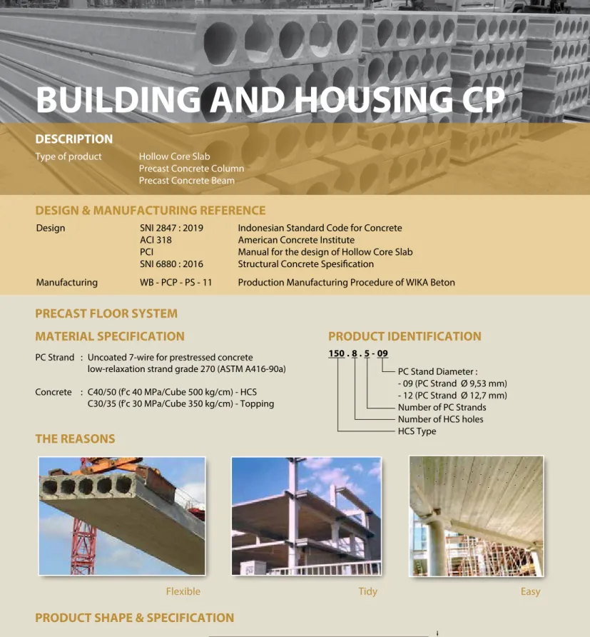
- Building and Housing Components.
- Fences.
- Underground Utility Ducting, etc.
The main product of this structures is concrete pipe, which consists of low pressure pipes and pressure pipes. The low pressure pipe is used as sewerage, water distribution, etc.
The pressure pipe is produced using vibro pressed centrifugal system to get high density concrete with low permeability and low shrinkage.
It is used as raw water transmission pipes as part of water treatment plant which requires very high resistance to the water pressure.
PILES
BRIDGE CONCRETE PRODUCTS
RETAINING WALL CONCRETE
PRODUCTS OTHER PRECAST CONCRETE
PRODUCTS
PRESTRESSED SPUN CONCRETE POLES
HYDRO STRUCTURE CONCRETE PRODUCTS
MARINE STRUCTURE CONCRETE PRODUCTS
RAILWAY CONCRETE PRODUCTS
PC POLES
DESCRIPTION
Type of Poles
DPC Poles Prestress Concrete Poles for Electrical Distribution Line TPC Poles Prestress Concrete Poles for Telecommunication Line
SDPC Poles Segmental Prestress Concrete Poles for Electrical Distribution Line STPC Poles Segmental Prestress Concrete Poles for Telecommunication Line System of Joints Bolt and nuts for SDPC Poles
Welding at steel joint plate for STPC Poles
DESIGN & MANUFACTURING REFERENCE
Design SNI 6880 : 2016 Structural Concrete Specification
SPLN D3.019 - 2:2021 Prestressed Concrete Poles for Distribution Line SPLN 121 : 1996 Prestressed Concrete Poles for Transmision Line
STEL-2001 Ver.2 Telecommunication Specification - Prestressed Concrete Spun Poles SNI 2847 : 2019 Indonesian Concrete Code for Concrete
Manufacturing WB - PCP - PS - 05 Production Manufacturing Procedure
PRODUCT SHAPE & SPECIFICATION | PC POLES
POLE LENGTH
TOP DIAMETER BOTTOM
DIAMETER
PRESTRESSING STEEL SPIRAL
Concrete Compressive Strength fc' = 42 MPa
Electrical Distribution Line PC Poles DPC
DPC DPC
DPC DPC
9 11 12
13 14
200 350 200 350 200 350 500 350 500 350 500
157 190 190 190 190 190 190 190 190 190 190
277 310 337 337 350 350 350 363 363 377 377
580 710 1.050 1.050 1.230 1.230 1.230 1.410 1.410 1.670 1.670
TPC TPC
7 9
150 150
124 124
202 224
300 430 Telecommunication Line PC Poles
SDPC SDPC SDPC
7 9 11
100 100 200 200
124 157 157 190
202 277 277 337
300 580 580 1.050 Segmental Electrical Distribution Line PC Poles Class Length
(m)
Horizontal Load (daN)
Weight (kg/pcs) Type
Top (mm)
Bottom (mm) Outside Diameter
PRODUCT APPLICATION
January - 2022
PC POLES
Concrete Compressive Strength fc' = 50 MPa
Segmental Electrical Transmission Line PC Poles Class Length
(m)
Horizontal Load (daN)
Weight (kg/pcs) Type
Top (mm)
Bottom (mm)
Outside Diameter
TRANSMISSION PC POLES APPLICATION
POLES FOUNDATION TYPE
POLES INSTALLATION METHOD
Installation by Lifting Crane Installation by Box Equipment Embeded foundation Base Plate foundation STPC
STPC
STPC
STPC
STPC
STPC
STPC
STPC 17
18
19
22
23
25
27
30
800 1.000 1.200 800 1.000 1.200 800 1.000 1.200 800 1.000 1.200 800 1.000 1.200 800 1.000 1.200 800 1.000 1.200 800 1.000 1.200
245 290 290 245 290 290 245 290 290 245 290 290 245 290 290 245 290 290 245 290 290 245 290 290
500 545 545 515 560 560 530 575 575 575 620 620 590 635 635 620 665 665 650 695 695 695 740 740
3.030 3.650 3.650 3.320 3.990 3.990 3.630 4.350 4.350 4.650 5.510 5.510 5.010 5.930 5.930 5.820 7.040 7.040 6.670 7.800 7.800 8.100 9.400 9.400
ITEM REFERENCE DESCRIPTION SPECIFICATION Aggregate ASTM C33/C33M-18 Standar Specification for Concrete
Aggregates Cement SNI 2049 : 2015
SNI 7064 : 2014 Portland Cement
Portland Cement Composite Standard Product Type I Special Order : Type II or V Admixture ASTM C494/C494M-19 Standar Specification for Chemmical
Admixture for Concrete Type F : High Range Water Reducing Admixture
PC Strand ASTM A416/A416M-21
SNI 1154 : 2016 Standar Specification for Steel Strand Uncoated Seven-Wire for Prestressed Concrete
Grade 270 (Low Relaxation Type) KBjP-P7 RB
PC Wire JIS G 3536 : 2014 SNI 1155 : 2016
Uncoated Stress-Relieved Steel Wires and Strand for Prestressed Concrete
SWPD 1 (Deformed Wire Type) KBjP-N
PC Bar JIS G 3137 : 2008
SNI 7701 : 2016 Small Size-Deformed Steel Bar for
Prestressed Concrete Grade D - Class 1 - SBPD 1275/1420 KBjP-Q N1
Rebar SNI 2052 : 2017 Reinforcement Steel for Concrete Steel Class : BjTS 420 A/B (Deformed) Steel Class : BjTP 280 (Round) Spiral Wire
Note : *) Chapter 4 Structural design requirement for piles with no seismic loading (In case pile is consider to seismic loading, piles detail should re-design refer to ACI 543R chapter 5
JIS G 3532 : 2011 Low Carbon Steel Wire SWM-P (Round Type)
Cold-reduced steel wire for the reinforcement of concrete and manufacture of welded fabric Joint Plate JIS G 3101 : 2015 Rolled Steel for General Structure SS400 (Tensile Strength 400 N/mm2)
Applicable steel product for steel plates and sheets, steel strip in coin, sections, flats and bars
Welding ANSI / AWS D1.1 : 2015 Structural Welding Code Steel AWS A5.1/E6013
NIKKO STEEL RB 26/ RD 260, LION 26 or equivalent Concrete SNI 2834 : 2000
SNI 2493 : 2011 Concrete Mix Design
Making and Curing Concrete Sample
PC PILES
DESCRIPTION
Type of PC Poles Prestress Concrete Pretension Spun Piles
Prestress Concrete Post-Tension Spun Piles (Cylinder Piles) Prestress Concrete Square Piles
Prestress Concrete Triangular Piles Prestress Concrete Spun Square Piles System of Joints Welding at steel joint plate
Type of Shoe Concrete Pencil Shoe (Standard) for PC Spun Piles, Spun Square Piles & Square Piles Mamira Shoe (Special Order) for PC Spun Piles
Method of Driving Dynamic Pile Driving : Diesel Hammer and Hydraulic Hammer Static Pile Driving : Hydraulic Static Pile Driver (Jacking Pile) Inner Borring System
MATERIAL SPECIFICATION
August - 2022
DESIGN AND MANUFACTURING REFERENCE
Design SNI 6880 : 2016 Structural Concrete Specification
ACI 543R* Design, Manufactured and Installation of Concrete Piles PCI 7
thEdition Precast and Prestressed Concrete
SNI 2847 : 2019 Indonesian Concrete Code for Concrete Manufacturing WB - PCP - PS - 05 Production Manufacturing Procedure
WB - PCP - PS - 06 Production Manufacturing Procedure for Cylinder Piles WB - PCP - PS - 08 Production Manufacturing Procedure for Square Piles
PC PILES
PILE SHAPE | PRESTRESSED CONCRETE PRETENSION SPUN PILES
PILE LENGTH SIZE
JOINT PLATE
WITHOUT JOINT PLATE (UPPER PILE) JOINT PLATE
MIDDLE / UPPER PILE
PILE LENGTH SIZE
JOINT PLATE
WITHOUT JOINT PLATE FOR SINGLE PILE PENCIL SHOE
BOTTOM / SINGLE PILE
PRESTRESSING STEEL SPIRAL
SIZE
WALL (t) PILE SECTION
SPECIFICATION | PRESTRESSED CONCRETE PRETENSION SPUN PILES
Concrete Compressive Strength fc' = 52 MPa Size
(mm)
Thickness Wall
(t)
Cross Section
(cm2)
Section inertia (cm4)
WeightUnit (kg/m)
Class
Bending Moment Crack*
(kN.m) Break (kN.m)
Allowable Compression
(kN)
Decompression Tension
(kN)
Handling with
“C Hook” at pile edge (m)
Length of Pile (m) Single/Double***
Unit Conversion 1 Ton = 9,806 kN
300
350
400
450
500
600
800
1.000**
1.200**
60
65
75
80
90
100
120
140
150
452
582
766
930
1.159
1.571
2.564
3.782
4.948
34.608
62.163
106.489
166.570
255.324
510.509
1.527.870
3.589.571
6.958.137 113
145
191
232
290
393
641
946
1.237 A2 A3 B C A1 A3 B C A2 A3 B C A1 A2 A3 B C A1 A2 A3 B C A1 A2 A3 B C A1 A2 A3 B C A1 A2 A3 B C A1 A2 A3 B C
24,5 29,4 34,3 39,2 34,3 41,2 49,0 58,8 53,9 63,7 73,5 88,3 73,5 83,4 98,1 107,9 122,6 103,0 122,6 137,3 147,1 166,7 166,7 186,3 215,7 245,2 284,4 392,2 451,1 500,1 539,3 637,4 735,5 804,1 912,0 1.029,6 1.176,7 1.176,7 1.274,8 1.421,9 1.667,0 1.961,2
36,8 44,1 61,8 78,4 51,5 61,8 88,3 117,7 80,9 95,6 132,4 176,5 110,3 125,0 147,1 194,2 245,2 154,4 183,9 205,9 264,8 333,4 154,4 183,9 205,9 264,8 333,4 588,4 676,6 750,2 970,8 1.274,8 1.103,2 1.206,1 1.367,9 1.853,3 2.353,4 1.765,1 1.912,2 2.132,8 3.000,6 3.922,4
714 696 664 637 916 898 865 828 1.210 1.192 1.126 1.088 1.490 1.453 1.418 1.385 1.315 1.843 1.806 1.754 1.738 1.648 2.506 2.487 2.415 2.329 2.239 4.065 3.976 3.920 3.798 3.629 5.990 5.901 5.774 5.626 5.420 7.824 7.648 7.511 7.365 7.042
221 288 409 513 294 361 484 626 369 437 683 833 374 511 641 764 1.034 520 656 849 910 1.253 671 741 1.008 1.328 1.678 1.188 1.513 1.721 2.180 2.836 1.782 2.109 2.579 3.133 3.927 2.375 3.021 3.529 4.079 5.325
10 11 12 14 11 12 13 15 11 12 14 16 11 13 14 15 17 12 13 15 15 18 13 14 16 18 19 16 18 19 21 23 18 20 21 23 25 21 22 24 25 29
11 / 16 12 / 17 14 / 19 15 / 20 12 / 17 13 / 18 14 / 20 16 / 21 13 / 18 13 / 19 16 / 21 17 / 23 13 / 18 14 / 19 15 / 21 16 / 22 18 / 24 14 / 19 15 / 21 16 / 22 17 / 23 19 / 25 15 / 21 16 / 21 17/ 23 19 / 25 21 / 28 18 / 24 20 / 26 20 / 27 22 / 29 24 / 30 21 / 27 22 / 29 23 / 30 25 / 30 27 / 30 23 / 29 25 / 30 26 / 30 27 / 30 30 / 30 Note : *) Crack Moment Based on JIS A 5335-1987 (Prestressed Spun Concrete Piles)
** ) Type of Shoe for Bottom Pile is Mamira Shoe
***) Number of Pile Lifting Position on Handling Process for Pile Driving Case 1 = Single Lifting Point Position : Minimum 1 m from end of Pile
Case 2 = Double Lifting Point Position (Using Pulley) : First Point Minimum 1,5 m from end of Pile
Second Point Minimum 1/3 L from end of Pile
PILE SHAPE | PRESTRESSED CONCRETE POST-TENSION SPUN PILES (CYLINDER PILES)
PILE SECTION PILE SEGMENT
POST-TENSION HOLE Ø 35 MM
WALL (t) SIZE
LONGITUDINAL REBAR
SPIRAL WIRE
SIZE
SEGMENT LENGTH
SPECIFICATION | PRESTRESSD CONCRETE POST-TENSION SPUN PILES (CYLINDER PILES)
Concrete Compressive Strength fc' = 52 MPa
PRODUCTION, PILE ASSEMBLING AND DISTRIBUTION PROCESS
Post-tensioning
Stockyard Facility Cylinder Pile Distribution
(mm)Size
Thickness Wall(t)
Cross Section
(cm2)
Section inertia (cm4)
Unit Weight
(kg/m) Class Allowable
Compression (kN)
Length of Pile (m) Single/Double*
(kN.m) (kN.m) Bending Moment Crack* Ultimate 800
1.000
1.200
1.500
1.800
2.000 120
140
150
170
200
200
2.564
3.782
4.948
7.103
10.053
11.309
1.527.870
3.589.517
6.958.136
15.962.533
32.672.563
46.369.907
641
946
1.237
1.776
2.513
2.827 A B C D A B C D A B C D A B C A B C A B C
392 539 637 735 735 1.030 1.177 1.324 1.177 1.667 1.961 2.059 2.157 2.942 3.334 3.628 4.609 5.099 4.707 5.786 6.570
637 784 1.177 1.275 1.079 1.716 2.157 2.402 1.373 2.648 3.040 3.138 2.599 4.315 5.099 4.168 6.374 7.551 5.246 7.747 9.463
4.020 3.824 3.628 3.481 5.884 5.491 5.393 5.197 7.845 7.305 6.962 6.864 11.179 10.590 10.198 15.984 15.493 14.905 17.945 17.357 16.866
24 / 36 24 / 36 30 / 42 30 / 42 24 / 36 30 / 42 30 / 48 36 / 48 30 / 48 36 / 48 42 / 54 42 / 60 36 / 48 36 / 54 42 / 60 36 / 48 36 / 54 42 / 60 35 / 55 40 / 60 45 / 65 Unit Conversion 1 Ton = 9,806 kN
Note : *) Number of Pile Lifting Position on Handling Process for Pile Driving Case 1 = Single Lifting Point Position : Minimum 1/8 L from end of Pile
Case 2 = Double Lifting Point Position (Using Pulley) : First Point Minimum 2 m from end of Pile
Second Point Minimum 1/3 L from end of Pile
SIZE
JOINT PLATE (MIDDLE PILE)
WITHOUT JOINT PLATE (UPPER PILE) MIDDLE / UPPER PILE JOINT PLATE
PILE LENGTH SIZE
JOINT PLATE (BOTTOM PILE)
WITHOUT JOINT PLATE (SINGLE PILE) BOTTOM / SINGLE PILE PENCIL SHOE
PILE SECTION PRESTRESSING STEEL
SPIRAL
SIZE
SPECIFICATION | PRESTRESSED CONCRETE SQUARE PILES
Concrete Compressive Strength fc' = 42 MPa Unit Conversion 1 Ton = 9,806 kN
Note : *) Length of Pile may exceed usual standard whenever lifted in certain position
SPECIFICATION | TYPICAL SPLICE
PILE SHAPE | PRESTRESSED CONCRETE SQUARE PILES
Size (mm)
Cross Section
(cm2)
Unit Weight
(kg/m) Class
Bending Moment Crack
(kN.m)
Ultimate (kN.m)
Allowable Compression
(kN)
Decompression Tension
(kN)
Length of Pile*
(m) Compatible
to Body Mcrack Optional Splice Class
200 x 200 250 x 250
300 x 300
350 x 350
400 x 400
450 x 450
500 x 500 400 625
900
1.225
1.600
2.025
2.500
100 156
225
306
400
506
625 A A B C A B C D A B C D A B C D A B C D A B C D
15,2 22,5 24,7 27,3 35,7 39,0 43,9 48,2 52,3 59,5 65,0 71,6 77,4 85,4 93,3 115,9 109,5 118,7 127,6 144,9 148,7 158,8 168,8 178,7
26,0 33,9 42,5 50,9 50,9 61,1 73,3 91,6 64,4 85,5 106,9 128,3 97,7 122,1 146,6 219,9 137,4 164,8 192,4 247,3 183,2 213,6 244,3 274,8
481 798 781 764 1.163 1.145 1.124 1.094 1.608 1.576 1.544 1.513 2.098 2.065 2.033 1.942 2.657 2.624 2.592 2.529 3.286 3.253 3.220 3.188
269 276 341 405 347 414 492 607 379 499 619 735 504 626 745 1.094 631 753 874 1.111 758 882 1.002 1.123
6 - 9 6 - 10 6 - 11 6 - 11 6 - 11 6 - 11 6 - 12 6 - 12 6 - 11 6 - 12 6 - 12 6 - 13 6 - 12 6 - 12 6 - 13 6 - 14 6 - 12 6 - 13 6 - 13 6 - 14 6 - 13 6 - 13 6 - 14 6 - 14
I III
II I IV III II I III
II I I IV III II I III III II I III
II I I
II IV - II V IV/V
- III/IV/V
IV - IV III/IV
V IV/V III/IV/V II/III/IV/V
IV IV III/IV II/III/IV
IV III/IV II/III/IV II/III/IV
Size (mm)
Bending Moment
Class Tension
Crack
(kN.m) Ultimate
(kN.m) Allowable (kN) Ultimate
(kN.m) 200 x 200
250 x 250
300 x 300
350 x 350
400 x 400
450 x 450
500 x 500 I II I II III IV I II III IV V I II III IV I II III IV V I II III IV I II III IV
15,3 7,5 31,1 29,3 22,9 12,6 58,4 44,4 42,0 38,8 22,9 75,2 66,8 56,0 32,4 119,6 110,6 92,3 84,1 38,9 154,9 138,0 127,7 64,2 193,4 161,9 148,5 74,1
20,7 10,0 42,0 39,5 31,1 17,1 78,9 60,0 56,7 52,5 31,0 101,5 90,1 75,6 43,6 161,5 149,3 124,6 113,6 52,6 209,2 186,3 172,3 86,7 261,1 218,6 200,3 100,1
410 160 541 406 406 240 820 615 541 406 240 820 820 541 271 1.157 867 820 615 271 1.446 1.157 867 410 1.163 1.157 867 410
461 180 609 457 457 270 923 692 609 457 270 923 923 609 305 1.301 976 923 692 305 1.626 1.301 976 461 1.308 1.300 976 461
Upper Pile 300x300 Class A Mom. Crack = 35,7 kN.m Mom. Ultimate = 50,9 kN.m Decomp. Tension = 347 kN
Splice : Class IV
Mom. Ultimate = 38,8 kN.m Tens. Allowable = 406 kN Splice of PC Piles having equivalent performance to the crack bending moment of the main body.
Application of optional splices should be approved by structure designer.
Bottom Pile 300x300 Class A Mom. Crack = 35,7 kN.m Mom. Ultimate = 50,9 kN.m Decomp. Tension = 347 kN
Upper Pile 300x300 Class A Mom. Crack = 35,7 kN.m Mom. Ultimate = 50,9 kN.m Decomp. Tension = 347 kN
Splice : Class V
Mom. Ultimate = 22,9 kN.m Tens. Allowable = 240 kN
Bottom Pile 300x300 Class A Mom. Crack = 35,7 kN.m Mom. Ultimate = 50,9 kN.m Decomp. Tension = 347 kN
EXAMPLES OF SPLICE SELECTION
Case 1 : Compatible to Body Moment Crack
Case 2 : Optional Splice
Piles Foundation for Power Plant or Industrial Factory
Piles for Marine Structurer Piles Foundation for Building Piles Foundation for Bridges
PRODUCT APPLICATION
Size (mm) 280 320
318,7 422,6
9.080 16.189
79,7 105,7
A B A B
6,5 8,8 8,7 11,8
9,0 17,4 10,9 21,1
414 387 559 531
269 276 341 405
6 - 8 6 - 9 6 - 8 6 - 9 Cross
Section (cm2)
Section inertia (cm4)
Unit Weight
(kg/m) Class
Bending Moment Crack
(kN.m) Ultimate (kN.m)
Allowable Compression
(kN)
Decompression Tension
(kN)
Length of Pile*
(m) Unit Conversion 1 Ton = 9,806 kN
PILE SHAPE | PRESTRESSED CONCRETE TRIANGULAR PILES
PILE LENGTH SIZE
JOINT PLATE (MIDDLE PILES)
WITHOUT JOINT PLATE (UPPER PILES) MIDDLE / UPPER PILES JOINT PLATE
PILE LENGTH SIZE
JOINT PLATE (BOTTOM PILES)
WITHOUT JOINT PLATE (SINGLE PILES) BOTTOM / SINGLE PILES PENCIL SHOE
PRESTRESSING STEEL SPIRAL
SIZE
WALL (t)
PILE SECTION
PILE SHAPE | PRESTRESSED CONCRETE SPUN SQUARE PILES
PILE LENGTH SIZE
JOINT PLATE (MIDDLE PILE)
WITHOUT JOINT PLATE (UPPER PILE) MIDDLE / UPPER PILE JOINT PLATE
PILE LENGTH SIZE
BOTTOM / SINGLE PILE
PRESTRESSING STEEL
SPIRAL
SIZE SIZE JOINT PLATE (MIDDLE PILE)
WITHOUT JOINT PLATE (UPPER PILE)
PILE SECTION
SPECIFICATION | PRESTRESSED CONCRETE SQUARE PILES
Concrete Compressive Strength fc' = 42 MPa
SPECIFICATION | PRESTRESSED CONCRETE SQUARE PILES
Concrete Compressive Strength fc' = 52 MPa Unit Conversion 1 Ton = 9,806 kN
Size (mm) 400 x 400
450 x 450 75
80
1.109
1.365
194.159
307.000
63,7 78,4 98,1 107,9 83,4 107,9 127,5 132,4 1.132,6
373 425 717 899 375 519 658 793 1.118
6 - 13 6 - 14 6 - 15 6 - 16 6 - 13 6 - 15 6 - 16 6 - 16 6 - 16 98,1
117,7 176,5 215,7 122,6 166,7 204,9 235,3 304,0
1.791 1.771 1.698 1.662 2.226 2.186 2.148 2.111 2.041 277
341 A2 A3 B C A1 A2 A3 B C Thickness
Wall (t)
Cross Section
(cm2)
Section inertia (cm4)
Unit Weight
(kg/m) Class
Bending Moment
Note : *) Length of Pile may exceed usual standard whenever lifted in certain position Crack
(kN.m)
Ultimate (kN.m)
Allowable Compression
(kN)
Decompression Tension
(kN)
Length of Pile*
(m)
INTERACTION DIAGRAM
INTERACTION DIAGRAM OF PC SPUN PILE
DIAMETER 300 INTERACTION DIAGRAM OF PC SPUN PILE
DIAMETER 350
AXIAL LOAD (kN)
MOMENT (kN-M)
AXIAL LOAD (kN)
MOMENT (kN-M)
INTERACTION DIAGRAM OF PC SPUN PILE DIAMETER 450
AXIAL LOAD (kN)
MOMENT (kN-M) INTERACTION DIAGRAM OF PC SPUN PILE
DIAMETER 400
AXIAL LOAD (kN)
MOMENT (kN-M)
INTERACTION DIAGRAM OF PC SPUN PILE DIAMETER 600
AXIAL LOAD (kN)
MOMENT (kN-M) INTERACTION DIAGRAM OF PC SPUN PILE
DIAMETER 500
AXIAL LOAD (kN)
MOMENT (kN-M)
INTERACTION DIAGRAM OF PC SPUN PILE DIAMETER 1000
AXIAL LOAD (kN)
MOMENT (kN-M)
INTERACTION DIAGRAM OF PC SPUN PILE DIAMETER 1200
AXIAL LOAD (kN)
MOMENT (kN-M) INTERACTION DIAGRAM OF PC SPUN PILE
DIAMETER 800
AXIAL LOAD (kN)
MOMENT (kN-M)
Diagram Interaction of crack load Diagram Interaction of nominal load
Diagram Interaction of crack load Diagram Interaction of nominal load
Diagram Interaction of crack load Diagram Interaction of nominal load
Diagram Interaction of crack load Diagram Interaction of nominal load
Diagram Interaction of crack load Diagram Interaction of nominal load
Diagram Interaction of crack load Diagram Interaction of nominal load
Diagram Interaction of crack load Diagram Interaction of nominal load
Diagram Interaction of crack load Diagram Interaction of nominal load
Diagram Interaction of crack load Diagram Interaction of nominal load
RAILWAY CONCRETE PRODUCT
DESCRIPTION
Type of Railway Product PC Sleepers Prestress Concrete Sleepers for Mainlane & Depo PC Bearers Prestress Concrete Bearers for Turnout & Scissors PC Catenary Poles Prestress Concrete Catenary Poles for Electrical Line
DESIGN & MANUFACTURING REFERENCE
Design PD No.10 Perumka Indonesian Railways Design Reference
AREMA Chapter 30 - 2009 American Railway Engineering and Maintenance of Way Association BS EN 13230 : 2016 (series) Railway Application - Track - Concrete Sleepers and Bearers
SNI 8828 : 2019 SNI Bantalan Beton dan Sistem Penambat untuk Jalan Rel AS 1085 : 2003 (series) Australian Standard
TB/T 3080 - 2030 Technical Concrete Sleeper Railway Industry Standards GOST 10629 - 1988 Prestressed Concrete Sleepers for Railway Wide 1.520 mm JIS A 5373 : 2010 Precast Prestressed Concrete Products
SNI 6880 : 2016 Structural Concrete Spesification
PRODUCT SHAPE | PC SLEEPERS
2440
330
195 220
SLEEPER S-35 BALLASTED
180
180
SPECIFICATION | PC SLEEPERS
Note : *) Type of Rail is available for R-33, R-38, R-40, R-42, R-50, R-54 & R-60
**) Type of fastening is available for Pindad E-Clip, Pandrol E-Clip, Vossloch Clip, DE-Clip or others adjustable to customer requirement Track
Gauge */**
(mm) N-1067 N-1067 S-1435 S-1435 S-1435
Ballasted Ballastless
Ballasted Ballastless Ballasted/Ballastless
180 180 250 120 300
150 150 200 100 50
2.000 2.000 2.440 2.150 2.600
52 52 62 52 62
190 250 300 270 328 Track Type Design Axle Load
(kN)
Design Speed (km/hour)
Sleeper Length (mm)
Compresive Strength
(MPa)
Sleeper Weight (kg)
April - 2022
Manufacturing WB - PCP - PS - 10 Production Manufacturing Procedure
2000
250
190
150
210
SLEEPER N-67 BALLASTED
SLEEPER N-67
BALLASTLESS SLEEPER S-35
BALLASTLESS 150
2000
240
205 185
214
2150
271
241 140
197
RAIL W AY CP
PRESTRESSING STEEL SPIRAL
WALL (t)
PRODUCT SHAPE | PC BEARER FOR SWITCHES AND CROSSINGS SPECIFICATION | PC CATENARY POLES
Concrete Compressive Strength fc' = 52 MPa
Type C-50 C-65 C-75 C-110 C-150
350 350 350 400 450
5,00 6,50 7,50 11,00 15,00
10,00 13,00 15,00 22,00 30,00
11 - 14 11 - 14 11 - 14 11 - 14 11 - 14 70
70 70 75 80
616 616 616 766 930
64.115 64.115 64.115 106.489 166.570
154 154 154 191 232 Outside
Diameter
(mm) Crack
(ton.m) Ultimate (ton.m) Thickness
Wall (mm)
Cross Section
(cm2)
Section Inertia (cm4)
Unit Weight (kg/m)
Length of Pile
(m) Bending Moment
TURNOUT ARRANGEMENT LENGTH
TOP DEPTH
BOTTOM
SPECIFICATION | PC BEARER FOR SWITCHES AND CROSSINGS
Concrete Compressive Strength fc' = 62 MPa
Type N1067
S1435 154 Variable 220 300 260
Length Depth Bottom Top Unit Weight
(kg/m)
Dimension (mm)
Note :
1. Type, quantity and dimension of PC Bearer for Switches and Crossing per arrangement is adjustable to customer requirement 2. Type of fastening is adjustable to customer requirement
PRODUCT SHAPE | PC CATENARY POLES
PRODUCT APPLICATION
Railway Sleepers Railway Catenary Poles Railway Turnout Railway Bridges
BRIDGE CONCRETE PRODUCT
DESCRIPTION
Type of PC Girder PC U Girder PC I Girder
PC Voided Slab PC Segmental Box Girder Type of Precast Bridge Floor PC Double Tee PC / RC Full Depth Slab
PC Channel Girder Prestress System Post-Tension or Pretension
DESIGN AND MANUFACTURING REFERENCE
Design SNI 6880 : 2016 Structural Concrete Specification
SNI T - 12 - 2004 Indonesian Concrete Code : Bridge Concrete Design SNI 1725 : 2016 Indonesian Concrete Code : Design Load for Bridge PCI 7
thEdition Precast and Prestressed Concrete
AASHTO - LRFD Bridge Design Specifications 2017 Manufacturing WB - PCP - PS - 07 Production Manufacturing Procedure
WB - PCP - PS - 08 Production Precast Product Procedure
GIRDER SHAPE & DIMENSION | PC U GIRDER
SPECIFICATION | POST-TENSION PC U GIRDER
Note : Based on bridge load refer to SNI 1725 : 2016 and assume bridge section parameter : 250 mm for CIP Slab, 70 mm concrete deck slab and 50 mm (+50 mm / -0 mm) asphaltic layer
August - 2022 PC U H-120 cm
Spacing/fc'Beam (cm/MPa)
Beam Support Reaction (kN) Span
(m) 13 1415 1617 18 1920 21 2223 2425 26 2728 29 3031 3233 34 3536 37 3839 4041 42 4344 45 4647 4849 50
310/45 310/45 310/45 310/45 310/45 310/45 310/45 310/45 310/45 270/45
412 442472 506539 569 599629 660 612
495 504513 520526 532 537542 546 496
1.436 1.494 1.549 1.607 1.663 1.713 1.763 1.811 1.859 1.702 VDL VLL Vult
PC U H-140 cm Spacing/fc'Beam
(cm/MPa)
Beam Support Reaction (kN)
310/45 310/45 310/45 310/45 310/45 310/45 310/45 310/50 310/50 310/50 310/50 270/50
599 630662 694 725757 788820 858 890921 988
532 537542 546 550554 557561 575 589603 562
1.749 1.800 1.850 1.900 1.949 1.997 2.045 2.095 2.170 2.237 2.304 2.304 VDL VLL Vult
PC U H-165 cm Spacing/fc'Beam
(cm/MPa)
Beam Support Reaction (kN)
310/45 310/45 310/45 310/45 310/45 310/50 310/50 270/50
849881 913945 997 1.009 1.041 988
587590 592603 617 631638 561
2.172 2.219 2.266 2.328 2.395 2.463 2.518 2.304 VDL VLL Vult
PC U H-185 cm Spacing/fc'Beam
(cm/MPa)
Beam Support Reaction (kN)
310/50 310/50 310/50 310/50 310/50 310/60 310/60 270/60 270/60
1.124 1.163 1.197 1.231 1.264 1.297 1.331 1.260 1.290
645652 659 666673 680686 604 610
2.634 2.698 2.754 2.811 2.867 2.924 2.981 2.730 2.781 VDL VLL Vult
PC U H-210 cm Spacing/fc'Beam
(cm/MPa)
Beam Support Reaction (kN)
310/60 310/60 310/60 310/60 270/60
1.481 1.518 1.552 1.587 1.505
701 708715 722635
3.194 3.253 3.311 3.370 3.095 VDL VLL Vult
PC U H-230 cm Spacing/fc'Beam
(cm/MPa)
Beam Support Reaction (kN)
310/60 310/60 310/60 310/60 310/70 270/70 270/70
1.703 1.740 1.777 1.814 1.851 1.830 1.866
729 736 743750 757665 671
3.526 3.586 3.647 3.707 3.768 3.564 3.621 VDL VLL Vult
A
H
300 300
H
(cm) A
(cm) Area
(cm2) Inertia
(cm4) 120140
165 185210 230
172172 190 190190 208
9.178 10.366 11.878 13.066 14.678 15.936
12.633.291 19.634.469 31.358.776 43.340.406 62.328.088 80.742.448
BRIDGE CP
GIRDER SHAPE & DIMENSION | PC I GIRDER
210 80
70 20
PC I H-210
Area : 7.495 cm2 Inertia : 41.087.033 cm4 170
80
70 20
PC I H-170
Area : 6.695 cm2 Inertia : 23.641.085 cm4 160
55
65 18
PC I H-160
Area : 4.773 cm2 Inertia : 14.611.104 cm4 125
35
65 17
PC I H-125
Area : 3.167 cm2 Inertia : 5.496.255 cm4 35
90
65 17
PC I H-90
Area : 2.572 cm2 Inertia : 2.266.607 cm4
SPECIFICATION | POST-TENSION PC I GIRDER
Note : Based on bridge load refer to SNI 1725 : 2016 and assume bridge section parameter : 250 mm for CIP Slab, 70 mm concrete deck slab and 50 mm (+50 mm / -0 mm) asphaltic layer
*) H-210 Dapped End with additional web thickness 50 mm and RIB Span
(m) 10 11 12 13 14 15 16 17 18 19 20 21 22 23 24 25 26 27 28 29 30 31 32 33 34 35 36 37 38 39 40 41 42 43 44 45*
46*
47*
48*
49*
50*
185/45 185/45 185/45 185/45 185/45 185/45 140/45
146 160 175 189 203 218 190
316 327 337 345 351 357 303
761 800 835 868 899 928 793 PC I H-90 cm
Beam Support Reaction (kN) VDL VLL Vult
Beam Spacing/fc'
(cm/MPa)
185/45 185/45 185/45 185/45 185/45 185/45 140/45 140/50
249 264 279 294 309 324 280 292
362 367 371 374 378 380 321 323
976 1.004 1.031 1.057 1.082 1.107 940 960 PC I H-125 cm
Beam Support Reaction (kN) VDL VLL Vult
Beam Spacing/fc'
(cm/MPa)
185/45 185/45 185/45 185/45 185/45 185/45 185/45 185/45 140/45 140/45
393 410 427 444 460 477 494 511 452 466
383 386 388 390 392 393 395 397 333 334
1.197 1.223 1.249 1.274 1.300 1.325 1.350 1.374 1.178 1.199 PC I H-160 cm
Beam Support Reaction (kN) VDL VLL Vult
Beam Spacing/fc'
(cm/MPa)
185/45 185/45 185/45 185/45 185/45 185/45 185/45 185/45 185/50 140/45 140/45 140/50
587 606 628 647 666 684 703 722 741 655 671 687
398 399 401 402 403 404 405 406 410 341 342 343
1.469 1.496 1.526 1.553 1.579 1.605 1.630 1.656 1.687 1.447 1.469 1.490 PC I H-170 cm
Beam Support Reaction (kN) VDL VLL Vult
Beam Spacing/fc'
(cm/MPa)
185/45 185/45 185/45 185/45 185/45 185/45 185/45 185/45 185/50 185/50 185/60 185/60 185/60 140/60 140/60 140/60
735 754 774 794 814 833 858 878 897 917 996 1.017 1.038 929 946 966
404 405 406 410 414 418 422 427 431 435 439 443 447 346 347 348
1.665 1.692 1.719 1.751 1.784 1.817 1.855 1.888 1.921 1.954 2.092 2.127 2.162 1.824 1.848 1.876 PC I H-210 cm
Beam Support Reaction (kN) VDL VLL Vult
Beam Spacing/fc'
(cm/MPa)
GIRDER SHAPE & DIMENSION | PC VOIDED SLAB
PC VS-74/97 Area : 5.032 cm2 Inertia : 2.977.551 cm4 PC VS-57/97
Area : 4.397 cm2 Inertia : 1.411.372 cm4
PC VS-62/97 Area : 4.420 cm2 Inertia : 1.785.520 cm4
PC VS-66/97 Area : 4.784 cm2 Inertia : 2.170.299 cm4
SPECIFICATION | POST-TENSION VOIDED SLAB
Note : Based on bridge load refert to SNI 1725 : 2016 and assume bridge cross section parameter only 50 mm asphaltic layer without over topping CIP Slab
SPECIFICATION | POST-TENSION VOIDED SLAB WITH OVERTOPPING
30 39
74
97 30
33
66
97 30
31
62
97 25
28,5
57 97
PC VS-57+18/97
Area : 5.766 cm2 Inertia : 2.855.560 cm4
PC VS-62+18/97
Area : 5.815 cm2 Inertia : 3.435.186 cm4
PC VS-66+18/97
Area : 6.201 cm2 Inertia : 4.020.154 cm4
PC VS-74+18/97
Area : 6.492 cm2 Inertia : 5.300.499 cm4
18
30 39
74
97 30
33
66
97 25
28,5
57
18 18
97
30 31
62 97
18
Span (m)
6 7 8 9 10 11 12 13 14 15 16
PC VS 57/97 PC VS 62/97 PC VS 66/97 PC VS 74/97
97/50 97/50 97/50 97/50 97/50 97/50
39 45 51 57 63 69
195 209 219 228 234 239
400 433 459 482 501 518 Beam Support
Reaction (kN) VDL VLL Vult
Beam Spacing/fc'
(cm/MPa)
97/50 97/50 97/50 97/50 97/50 97/50 97/50
39 45 52 58 64 70 76
195 209 219 228 234 239 244
401 434 460 483 502 520 535 Beam Support
Reaction (kN) VDL VLL Vult
Beam Spacing/fc'
(cm/MPa)
97/50 97/50 97/50 97/50 97/50 97/50 97/50 97/50
42 49 55 62 69 75 82 89
195 209 219 228 234 239 244 248
404 438 465 488 508 526 542 557 Beam Support
Reaction (kN) VDL VLL Vult
Beam Spacing/fc'
(cm/MPa)
97/50 97/50 97/50 97/50 97/50 97/50 97/50 97/50 97/50 97/50 97/50
44 51 58 65 72 79 86 93 103 110 117
195 209 219 228 234 239 244 248 251 254 256
407 441 468 492 512 531 547 563 580 594 607 Beam Support
Reaction (kN) VDL VLL Vult
Beam Spacing/fc'
(cm/MPa)
Span (m)
6 7 8 9 10 11 12 13 14 15 16 17 18 19 20 21
PC VS 57/97 PC VS 62/97 PC VS 66/97 PC VS 74/97
97/50 97/50 97/50 97/50 97/50 97/50 97/50 97/50 97/50 97/60 97/70
61 71 81 91 101 111 121 131 143 152 162
111 119 125 130 134 137 139 141 143 145 146
279 306 329 350 369 388 405 421 440 455 470 Beam Support
Reaction (kN) VDL VLL Vult
Beam Spacing/fc'
(cm/MPa)
97/50 97/50 97/50 97/50 97/50 97/50 97/50 97/50 97/50 97/50 97/60 97/70
62 72 82 92 102 112 122 132 144 154 164 174
111 119 125 130 134 137 139 141 143 145 146 147
280 307 330 351 371 389 406 423 442 457 473 487 Beam Support
Reaction (kN) VDL VLL Vult
Beam Spacing/fc'
(cm/MPa)
97/50 97/50 97/50 97/50 97/50 97/50 97/50 97/50 97/50 97/50 97/60 97/70 97/70 97/70
65 75 86 96 107 117 128 138 151 161 172 182 193 203
111 119 125 130 134 137 139 141 143 145 146 147 148 149
283 311 335 356 376 395 413 430 450 466 482 497 512 528 Beam Support
Reaction (kN) VDL VLL Vult
Beam Spacing/fc'
(cm/MPa)
97/50 97/50 97/50 97/50 97/50 97/50 97/50 97/50 97/50 97/50 97/50 97/60 97/70 97/70 97/70 97/70
67 78 89 100 110 121 132 143 156 167 177 188 199 210 221 231
111 119 125 130 134 137 139 141 143 145 146 147 148 149 150 151
286 314 338 360 381 400 418 436 456 472 489 505 520 536 551 566 Beam Support
Reaction (kN) VDL VLL Vult
Beam Spacing/fc'
(cm/MPa)
SEGMENT SHAPE & DIMENSION | PC BOX GIRDER SPAN UP TO 50 m (HIGHWAY & LIGHT RAIL TRAIN)
Height Width of slab Thickness of slab Web
Thickness Note
Top Bottom Top Bottom
2.600 mm 10.300 mm 4.000 mm 300 mm 277 mm Span by Span
External Stressing Span 40-50 m 225 mm
2.500 - 3.484 mm 13.000 mm 5.000 mm 250 - 443 mm 450 mm Balance Cantilever External Stressing Span 50-100 m 225 mm
2.400 mm 10.300 mm 4.300 mm 250 mm 300 mm Span by Span
External Stressing Span 30-40 m (Train) 300 mm
SPAN UP TO 100 m (HIGHWAY & LIGHT RAIL TRAIN)
SPAN UP TO 40 m (RAILWAY BRIDGE - RM1921 LOAD)
2.600
10.300
4.000 225
277
200
13.000
5.000 2.500 - 3.483
250
2791
443 R500
450 450
2.400
10.300
4.300 250
250
300 300
GIRDER SHAPE & SPECIFICATION | PC BULB TEE GIRDER
DIMENSION | PC BOX GIRDER
PC Bulb Tee H-230 Area : 13.677,5 cm2 Inertia : 104.700.913,6 cm4 230
240
25
120
Note : Based on bridge load refer to SNI 1725 : 2016 and assume bridge section parameter using 150 mm topping slab and 50 mm asphaltic layer
Span(m)
Bulb Tee Beam Weight (ton/pcs) Spacing/fc'
(cm/MPa)
Beam Support
VDL VLL Vult
Reaction (kN)
250/70 250/70 250/70 250/70 250/70 250/70
238 241 245 248 255 255
1.727 1.755 1.782 1.810 1.838 1.865
648 653 659 664 669 675
3.358 3.403 3.448 3.492 3.537 3.582 55
56 57 58 59 60
SLAB SHAPE & DIMENSION | PC DOUBLE TEE FOR TRUSS BRIDGE FLOOR
2100 560
200 310 50
400 100 1.100 100 400
PC DT H-56 for Class A bridge Area : 4.976 cm2 Inertia : 758.607,78 cm4
PC DT H-56 for Class B bridge Area : 4.075,97 cm2 Inertia : 702.011,25 cm4 PC DOUBLE TEE FOR TRUSS BRIDGE FLOOR
Patent Number : ID P0026747 Certified by The Ministry of Law and Human Right
Republic of Indonesia
Note :
CLASS A : 7 meter width of traffic lane with additional 1 meter kerb in each side of bridge CLASS B : 6 meter width of traffic lane with additional 0,5 meter kerb in each side of bridge
SLAB SHAPE & SPECIFICATION | FULL DEPTH SLAB FOR CONCRETE/STEEL BRIDGE FLOOR
FULL DEPTH SLAB FOR BRIDGE
SLAB LENGTH (WIDTH OF BRIDGE)
ROADWAY SLAB SLAB BEAM CONNECTION
SLAB WIDTH
CONCRETE / STEEL GIRDER SLAB THICKNESS
SLAB BEAM CONNECTION HOLE
PRODUCT APPLICATION
PC I or PC U Girder for Bridges Box Girder Bridges Double Tee Slab for Bridge Floor Full Depth Slab for Bridge Floor
150 150
1.650 560
200 310 50
175100 1.100 100175
150 150
DOUBLE TEE LATERAL STRESSING SYSTEM STRUCTURAL JOINT
STEEL TRUST BEAM 560
GIRDER SHAPE & DIMENSION | PC CHANNEL GIRDER
SPECIFICATION | PRETENSION CHANNEL GIRDER
CG 60 x 120
Area : 4.329 cm2 Inertia : 1.293.103 cm4
CG 70 x 120
Area : 4.806 cm2 Inertia : 2.023.171 cm4
CG 80 x 120
Area : 5.274 cm2 Inertia : 2.968.087 cm4
CG 90 x 120
Area : 5.728 cm2 Inertia : 4.142.306,02 cm4 1.200
580 50
50
20 20
240 240
PROJECT REFERENCE
Project Simpang Susun Semanggi (Box Girder)
Project Simpang Susun Semanggi
(Box Girder) Project Jalan Layang Kereta Api
(Box Girder) Project MRT Jakarta
(Box Girder) Span
(m)
6,6 7,6 8,69,6 10,6 11,6 12,613,6 14,6 15,6 16,617,6 18,6 19,6 20,621,6
CG 60 x 120 CG 70 x 120 CG 80 x 120 CG 90 x 120
120/50 120/50 120/50 120/50 120/50 120/50 120/50 120/60
44 50 5764 71 78 8791
220 231 237242 245 247 248249
455 483 504522 536 549 564571 Beam Support
Reaction (kN) VDL VLL Vult
Beam Spacing/fc'
(cm/MPa)
120/50 120/50 120/50 120/50 120/50 120/50 120/50 120/50 120/50 120/60 120/60
47 55 6269 77 84 9299 107 114 121
224 235 242246 249 252 253254 254 254 254
467 496 518536 552 565 578589 600 610 620 Beam Support
Reaction (kN) VDL VLL Vult
Beam Spacing/fc'
(cm/MPa)
120/50 120/50 120/50 120/50 120/50 120/50 120/50 120/50 120/50 120/50 120/50 120/60 120/60
51 59 6775 83 91 10799 115 123 131138 146
228 239 246250 254 256 257258 258 259 258258 258
478 508 531550 566 580 593606 617 628 639649 659 Beam Support
Reaction (kN) VDL VLL Vult
Beam Spacing/fc'
(cm/MPa)
120/50 120/50 120/50 120/50 120/50 120/50 120/50 120/50 120/50 120/50 120/50 120/50 120/60 120/60 120/70 120/70
54 63 7180 88 97 105114 122 131 140148 156 165 173182
174 170 166254 257 259 261262 262 262 262262 262 262 262262
384 388 393563 580 595 608621 633 645 656667 678 689 700712 Beam Support
Reaction (kN) VDL VLL Vult
Beam Spacing/fc'
(cm/MPa) 1.170
15 15 15 1.170 15 15 1.170 15 15 1.170 15
50 150400
600 50 150500 50 150600 50 150700
1.200
580 50
50
25 25
235 235
1.200
580 50
50
30 30
230 230
1.200
580 50
50
35 35
225 225
700 800 900