NO COPYING WITHOUT BSI PERMISSION EXCEPT AS PERMITTED BY COPYRIGHT LAW
BSI Standards Publication
Geometrical product specifications (GPS) —
Acceptance and reverification tests for coordinate measuring machines (CMM)
Part 5: CMMs using single and multiple stylus contacting probing systems (ISO 10360-5:2010)
--`,,```,,,,````-`-`,,`,,`,`,,`---
National foreword
This British Standard is the UK implementation of EN ISO
10360-5:2010. It supersedes BS EN ISO 10360-5:2001 and DD ISO/PAS 12868:2009 which are withdrawn.
The UK participation in its preparation was entrusted to Technical Committee TDW/4, Technical Product Realization.
A list of organizations represented on this committee can be obtained on request to its secretary.
This publication does not purport to include all the necessary provisions of a contract. Users are responsible for its correct application.
© BSI 2010
ISBN 978 0 580 57466 5 ICS 17.040.30
Compliance with a British Standard cannot confer immunity from legal obligations.
This British Standard was published under the authority of the Standards Policy and Strategy Committee on 30 November 2010.
Amendments issued since publication
Date Text affected
Copyright British Standards Institution
--`,,```,,,,````-`-`,,`,,`,`,,`---
NORME EUROPÉENNE
EUROPÄISCHE NORM
September 2010ICS 17.040.30 Supersedes EN ISO 10360-5:2000
English Version
Geometrical product specifications (GPS) - Acceptance and reverification tests for coordinate measuring machines (CMM) - Part 5: CMMs using single and multiple stylus contacting probing
systems (ISO 10360-5:2010)
Spécification géométrique des produits (GPS) - Essais de réception et de vérification périodique des machines à mesurer tridimensionnelles (MMT) - Partie 5: MMT utilisant
des systèmes de palpage à stylet simple ou à stylets multiples (ISO 10360-5:2010)
Geometrische Produktspezifikation (GPS) - Annahmeprüfung und Bestätigungsprüfung für Koordinatenmessgeräte (KMG) - Teil 5: Prüfung der
Antastabweichungen von KMG mit berührendem Messkopfsystem (ISO 10360-5:2010)
This European Standard was approved by CEN on 12 June 2010.
CEN members are bound to comply with the CEN/CENELEC Internal Regulations which stipulate the conditions for giving this European Standard the status of a national standard without any alteration. Up-to-date lists and bibliographical references concerning such national standards may be obtained on application to the CEN Management Centre or to any CEN member.
This European Standard exists in three official versions (English, French, German). A version in any other language made by translation under the responsibility of a CEN member into its own language and notified to the CEN Management Centre has the same status as the official versions.
CEN members are the national standards bodies of Austria, Belgium, Bulgaria, Croatia, Cyprus, Czech Republic, Denmark, Estonia, Finland, France, Germany, Greece, Hungary, Iceland, Ireland, Italy, Latvia, Lithuania, Luxembourg, Malta, Netherlands, Norway, Poland, Portugal, Romania, Slovakia, Slovenia, Spain, Sweden, Switzerland and United Kingdom.
EUROPEAN COMMITTEE FOR STANDARDIZATION C O M I T É E U R O P É E N D E N O R M A L I S A T I O N E U R O P Ä I S C H E S K O M I T E E FÜ R N O R M U N G
Management Centre: Avenue Marnix 17, B-1000 Brussels
© 2010 CEN All rights of exploitation in any form and by any means reserved worldwide for CEN national Members.
Ref. No. EN ISO 10360-5:2010: E
--`,,```,,,,````-`-`,,`,,`,`,,`---
3
Foreword
The text of ISO 10360-5:2010 has been prepared by Technical Committee ISO/TC 213 “Dimensional and geometrical product specifications and verification” of the International Organization for Standardization (ISO) and has been taken over as EN ISO 10360-5:2010 by Technical Committee CEN/TC 290 “Dimensional and geometrical product specification and verification” the secretariat of which is held by AFNOR.
This European Standard shall be given the status of a national standard, either by publication of an identical text or by endorsement, at the latest by March 2011, and conflicting national standards shall be withdrawn at the latest by March 2011.
Attention is drawn to the possibility that some of the elements of this document may be the subject of patent rights. CEN [and/or CENELEC] shall not be held responsible for identifying any or all such patent rights.
This document supersedes EN ISO 10360-5:2000.
According to the CEN/CENELEC Internal Regulations, the national standards organizations of the following countries are bound to implement this European Standard: Austria, Belgium, Bulgaria, Croatia, Cyprus, Czech Republic, Denmark, Estonia, Finland, France, Germany, Greece, Hungary, Iceland, Ireland, Italy, Latvia, Lithuania, Luxembourg, Malta, Netherlands, Norway, Poland, Portugal, Romania, Slovakia, Slovenia, Spain, Sweden, Switzerland and the United Kingdom.
Endorsement notice
The text of ISO 10360-5:2010 has been approved by CEN as a EN ISO 10360-5:2010 without any modification.
Copyright British Standards Institution
--`,,```,,,,````-`-`,,`,,`,`,,`---
Contents
PageForeword ...v
Introduction...vi
1 Scope ...1
2 Normative references...2
3 Terms and definitions ...2
4 Symbols...6
5 Requirements for metrological characteristics... 7
5.1 Single-stylus probing error ...7
5.2 Single-stylus probing configuration...8
5.3 Multi-stylus probing errors and values ...8
5.4 Multi-stylus probing configurations ...9
5.5 Styli ...9
5.6 Environmental conditions ...9
5.7 Operating conditions ...9
6 Acceptance tests and reverification tests ...10
6.1 General ...10
6.2 Single-stylus probing configuration...10
6.2.1 Application ...10
6.2.2 Principle...10
6.2.3 Measuring equipment ...10
6.2.4 Procedure ...11
6.2.5 Derivation of test results ...12
6.3 Fixed multi-probe and multi-stylus probing systems...12
6.3.1 Principle...12
6.3.2 Measuring equipment ...13
6.3.3 Procedure ...14
6.3.4 Data analysis...15
6.4 Articulating probing systems...16
6.4.1 Principle...16
6.4.2 Measuring equipment ...17
6.4.3 Procedure ...17
6.4.4 Data analysis...19
7 Compliance with specification...19
7.1 Acceptance tests ...19
7.2 Reverification tests ...20
8 Applications ...20
8.1 Acceptance tests ...20
8.2 Reverification tests ...20
8.3 Interim checks ...20
9 Indication in product documentation and data sheets...21
Annex A (informative) Symbols and subscripts ...23
Annex B (informative) Checking the probing system prior to the ISO 10360-2 test ...24
Annex C (informative) Interpretation of multi-stylus test results...25
Annex D (normative) Maximum permissible error/limit figures ...27
--`,,```,,,,````-`-`,,`,,`,`,,`---
iv © ISO 2010 – All rights reserved Annex E (informative) Relation to the GPS matrix model ...28 Bibliography ...30
Copyright British Standards Institution
--`,,```,,,,````-`-`,,`,,`,`,,`---
Foreword
ISO (the International Organization for Standardization) is a worldwide federation of national standards bodies (ISO member bodies). The work of preparing International Standards is normally carried out through ISO technical committees. Each member body interested in a subject for which a technical committee has been established has the right to be represented on that committee. International organizations, governmental and non-governmental, in liaison with ISO, also take part in the work. ISO collaborates closely with the International Electrotechnical Commission (IEC) on all matters of electrotechnical standardization.
International Standards are drafted in accordance with the rules given in the ISO/IEC Directives, Part 2.
The main task of technical committees is to prepare International Standards. Draft International Standards adopted by the technical committees are circulated to the member bodies for voting. Publication as an International Standard requires approval by at least 75 % of the member bodies casting a vote.
Attention is drawn to the possibility that some of the elements of this document may be the subject of patent rights. ISO shall not be held responsible for identifying any or all such patent rights.
ISO 10360-5 was prepared by Technical Committee ISO/TC 213, Dimensional and geometrical product specifications and verification.
This second edition cancels and replaces the first edition (ISO 10360-5:2000), which has been technically revised, and ISO/PAS 12868:2009.
ISO 10360 consists of the following parts, under the general title Geometrical Product Specifications (GPS) — Acceptance and reverification tests for coordinate measuring machines (CMM):
⎯ Part 1: Vocabulary
⎯ Part 2: CMMs used for measuring linear dimensions
⎯ Part 3: CMMs with the axis of a rotary table as the fourth axis
⎯ Part 4: CMMs used in scanning measuring mode
⎯ Part 5: CMMs using single and multiple stylus contacting probing systems
⎯ Part 6: Estimation of errors in computing Gaussian associated features
⎯ Part 7: CMMs equipped with video probing systems
⎯ Part 9: CMMs with multiple probing systems The following parts are under preparation:
⎯ Part 8: CMMs with optical distance sensors
⎯ Part 10: Laser trackers for measuring point-to-point distances
vi © ISO 2010 – All rights reserved
Introduction
This part of ISO 10360 is a geometrical product specification (GPS) standard and is to be regarded as a general GPS standard (see ISO/TR 14638). It influences chain link 5 of the chains of standards of size, distance, radius, angle, form, orientation, location, run-out and datums.
For more detailed information on the relation of this part of ISO 10360 to other standards and the GPS matrix model, see Annex E.
The acceptance and reverification tests described in this part of ISO 10360 are applicable to coordinate measuring machines (CMMs) that use contacting probes, with or without multiple styli or multiple articulated- probe positions, when measuring a workpiece.
Experience has shown that the multi-stylus errors calculated using this part of ISO 10360 are significant and, at times, the dominant errors in the CMM. Owing to the virtually infinite variety of modern CMM probing system configurations, the tests specified by this part of ISO 10360 have been limited to providing a testing format only. The tests are intended to provide information on the ability of a CMM to measure a feature or features, using a contacting probe and, when relevant, using multiple styli, multiple probes or multiple articulated-probe positions.
The situations to which they are applicable include
⎯ single-stylus probing systems,
⎯ multiple styli connected to the CMM probe (e.g. a star),
⎯ installations using an articulating probing system (motorized or manual) that can be prequalified,
⎯ installations using a repeatable probe-changing system,
⎯ installations using a repeatable stylus-changing system, and
⎯ multi-probe installations.
It is believed that the procedures given in this part of ISO 10360 will be helpful in identifying CMM system uncertainty components for specific measurement tasks, and that the user will be able to reduce errors by removing contributing elements such as long probe extensions and styli, then retesting the new configuration set.
The tests in this part of ISO 10360 are sensitive to many errors attributable to both the CMM and the probing system, and are to be performed in addition to the length-measuring tests given in ISO 10360-2.
The primary objective is to determine the practical performance of the complete CMM and probing system.
Therefore, the tests are designed to reveal measuring errors which are likely to occur when such a combined system is used on real workpieces, e.g. errors generated by the interaction between large probe-tip-offset lengths and uncorrected CMM rotation errors. The errors found here differ from those found in the EL tests in ISO 10360-2:2009, 6.5, because with multiple styli the net CMM travel may be very different from the measured length. See Annex C for more information.
Copyright British Standards Institution
--`,,```,,,,````-`-`,,`,,`,`,,`---
Geometrical product specifications (GPS) — Acceptance and reverification tests for coordinate measuring machines
(CMM) — Part 5:
CMMs using single and multiple stylus contacting probing systems
1 Scope
This part of ISO 10360 specifies acceptance and periodic reverification tests of CMM performance with contacting probing systems and is only applicable to CMMs using
⎯ any type of contacting probing system,
⎯ a discrete point probing mode, and
⎯ spherical or hemispherical stylus tip(s).
It complements ISO 10360-7, which is the module for CMMs with video probing systems, and ISO 10360-2, which is universal, i.e. not probe-type specific.
NOTE It is the CMM probing performance tests which are specified by the maximum permissible errors (MPEs), due to the impracticality of isolating the performance of the probing system from that of the CMM, even on a small artefact such as a test sphere.
This part of ISO 10360 applies to CMMs supplied with any of the following:
a) single-stylus probing system;
b) multi-stylus probing systems with fixed multiple styli attached to a single probe (e.g. “star” stylus);
c) multiple probing systems such as those with a stylus for each of their probes;
d) systems with articulating probing;
e) stylus and probe changing systems;
f) manual (non-driven) CMMs.
This part of ISO 10360 is not applicable to non-contacting probing systems, which require different testing procedures.
The terms “multi-stylus size error”, etc., should strictly be written “combined CMM and multi-stylus probing- system size error”, etc. For convenience, the wording has been truncated.
If it is desired to isolate the probing-system performance as far as is practical, the influence of the CMM can be minimized. See Annex C for more information.
--`,,```,,,,````-`-`,,`,,`,`,,`---
2
© ISO 2010 – All rights reserved2 Normative references
The following referenced documents are indispensable for the application of this document. For dated references, only the edition cited applies. For undated references, the latest edition of the referenced document (including any amendments) applies.
ISO 10360-1:2000, Geometrical Product Specifications (GPS) — Acceptance and reverification tests for coordinate measuring machines (CMM) — Part 1: Vocabulary
ISO 10360-2:2009, Geometrical Product Specifications (GPS) — Acceptance and reverification tests for coordinate measuring machines (CMM) — Part 2: CMMs used for measuring linear dimensions
ISO 14253-1, Geometrical Product Specifications (GPS) — Inspection by measurement of workpieces and measuring equipment — Part 1: Decision rules for proving conformance or non-conformance with specifications
ISO/IEC Guide 99, International vocabulary of metrology — Basic and general concepts and associated terms (VIM)
3 Terms and definitions
For the purposes of this document, the terms and definitions given in ISO 10360-1, ISO 14253-1, ISO/IEC Guide 99 and the following apply.
NOTE This clause contains eight definitions (3.6 to 3.13) which supersede fourteen similar definitions in Clause 9 of ISO 10360-1:2000. Some of these revised definitions are required to avoid ambiguities which would otherwise have been introduced with this edition of ISO 10360-5. Others effectively supersede identical definitions in ISO 10360-1, because the symbols used have been revised and expanded for clarification. The superseded definitions are 9.3, 9.4 and 9.15 to 9.26.
3.1
inferred probing-system qualification
probing-system qualification method where the parameters for each probing system attached to an articulation system are inferred by interpolation, extrapolation, or other relevant model, for significantly different angular position(s) from parameters acquired by empirical probing-system qualification (3.3) at a few angular positions
3.2
angular positioning device qualification
establishment of the parameters of the angular positioning device in an articulating probing system necessary for subsequent inferred probing-system qualification (3.1)
3.3
empirical probing-system qualification
probing-system qualification method where the parameters for each probing system attached to an articulation system must be acquired by measurement of the reference sphere at each angular position used
3.4
effective stylus tip diameter
diameter used for the tip correction vector, for compensating measured feature size, etc.
NOTE 1 For the position of the tip correction vector, see ISO 10360-1:2000, Figure 4.
NOTE 2 The effective stylus tip diameter may be a parameter established by a probing-system qualification.
3.5
probing-system pre-qualification
probing-system qualification which is separated from subsequent measurement by probe or stylus change(s), and/or articulating probing-system re-orientation(s)
Copyright British Standards Institution
--`,,```,,,,````-`-`,,`,,`,`,,`---
3.6
multi-stylus form (measurement) error PFTj
error of indication within which the range of Gaussian radial distances can be determined by a least-squares fit of points measured on a test sphere, the measurements being taken with five different styli on the one test sphere located anywhere in the measuring volume by a CMM using the discrete-point probing mode
See ISO 10360-1:2000, Figure 15.
NOTE 1 The character P in PFTj indicates that the error is associated with the probing-system performance, and the subscript F indicates that it is a form error. The subscript T indicates that the probing system conforms to Clause 1 of this part of ISO 10360 (i.e. tactile), thus enabling any alternative probing system to be clearly identified by the use of a different character at * in PF*j.
NOTE 2 There are four multi-stylus form errors based on different probing systems and methods of operation. These are designated as follows:
j = E, an articulating probing system using empirical qualification;
j = I, an articulating probing system using inferred qualification;
j = M, a fixed multi-stylus probing system;
j = N, a fixed multi-probe system.
NOTE 3 All the symbols used in this part of ISO 10360 are listed in Annex A.
3.7
multi-stylus size error PSTj
error of indication within which the diameter of a test sphere can be determined by a least-squares fit of points, the measurements being taken with five different styli on the one test sphere located anywhere in the measuring volume by a CMM using the discrete-point probing mode
NOTE 1 The subscript S in PSTj indicates that it is a size error.
NOTE 2 All the symbols used in this part of ISO 10360 are listed in Annex A.
3.8
multi-stylus location value PLTj
maximum of the ranges of the X, Y and Z coordinates within which the location of a test sphere can be determined by a least-squares fit of points, the measurements being taken with five different styli on the one test sphere located anywhere in the measuring volume by a CMM using the discrete-point probing mode NOTE 1 The subscript L in PLTj indicates that it is a location value.
NOTE 2 All the symbols used in this part of ISO 10360 are listed in Annex A.
NOTE 3 All values are absolute.
3.9
single-stylus form error PFTU
error of indication within which the range of radii can be determined by a least-squares fit of points measured on a test sphere, the measurements being performed by a CMM with a single stylus, using the discrete-point probing mode, with points taken on the test sphere located anywhere in the measuring volume
See ISO 10360-1:2000, Figure 15.
--`,,```,,,,````-`-`,,`,,`,`,,`---
4
© ISO 2010 – All rights reserved NOTE 1 The character P in PFTU indicates that the error is related primarily to the probing-system performance. The subscript U indicates use of a single (unique) stylus.NOTE 2 See 3.6 for information on F and T.
NOTE 3 All such characters used in this part of ISO 10360 are listed in Annex A.
NOTE 4 PFTU is identical to P in ISO 10360-2:2001.
3.10
single-stylus size error PSTU
error of indication of the difference between the diameter of a least-squares fit of points measured on a test sphere and its calibrated diameter, the measurements being performed by a CMM with a single stylus, using the discrete-point probing mode, with points taken on the test sphere located anywhere in the measuring volume
NOTE 1 The character P in PSTU indicates that the error is related primarily to the probing-system performance. The subscript U indicates use of a single (unique) stylus. The subscript S in PSTj indicates that it is a size error.
NOTE 2 All such characters used in this part of ISO 10360 are listed in Annex A.
3.11
maximum permissible multi-stylus form error PFTj, MPE
extreme value of the multi-stylus form error (3.6), PFTj, permitted by specifications, regulations, etc. for a CMM
NOTE 1 The maximum permissible value of the multi-stylus form error, PFTj, MPE, can be expressed in one of three forms:
a) PFTj, MPE = minimum of (A + LP/K) and B; or b) PFTj, MPE= (A + LP/K); or
c) PFTj, MPE = B where
A is a positive constant, expressed in micrometres and supplied by the manufacturer;
K is a dimensionless positive constant supplied by the manufacturer;
LP is the distance in 3D between the centres of the reference sphere and the test sphere, in millimetres;
B is the maximum permissible error PFTj, MPE, in micrometres, as stated by the manufacturer.
These forms are shown in Figures D.1, D.2 and D.3.
NOTE 2 A maximum permissible error (MPE) as opposed to a maximum permissible limit (MPL) specification is used when the test measurements determine errors; hence, testing an MPE specification requires the use of calibrated artefacts.
NOTE 3 PFTj, MPE can be specified by probe-tip-offset length or by the stylus system description.
3.12
maximum permissible multi-stylus size error PSTj, MPE
extreme value of the multi-stylus size error (3.7), PSTj, permitted by specifications, regulations, etc. for a CMM
Copyright British Standards Institution
--`,,```,,,,````-`-`,,`,,`,`,,`---
NOTE 1 The maximum permissible value of the multi-stylus size error, PSTj, MPE, can be expressed in one of three forms:
a) PSTj, MPE = minimum of (A + LP/K) and B; or b) PSTj, MPE = (A + LP/K); or
c) PSTj, MPE= B where
A is a positive constant, expressed in micrometres and supplied by the manufacturer;
K is a dimensionless positive constant supplied by the manufacturer;
LP is the distance in 3D between the centres of the reference sphere and the test sphere, in millimetres;
B is the maximum permissible error PSTj, MPE, in micrometres, as stated by the manufacturer.
These forms are shown in Figures D.1, D.2 and D.3.
NOTE 2 A maximum permissible error (MPE) as opposed to a maximum permissible limit (MPL) specification is used when the test measurements determine errors; hence, testing an MPE specification requires the use of calibrated artefacts.
NOTE 3 PSTj, MPE can be specified by probe-tip-offset length or by the stylus system description.
3.13
maximum permissible limit of the multi-stylus location value PLTj, MPL
extreme value of the multi-stylus location value (3.8), PLTj, permitted by specifications, regulations, etc. for a CMM
NOTE 1 The maximum permissible limit of the multi-stylus location value, PLTj, MPL, can be expressed in one of three forms:
a) PLTj, MPL= minimum of (A + LP/K) and B; or b) PLTj, MPL= (A + LP/K); or
c) PLTj, MPL = B where
A is a positive constant, expressed in micrometres and supplied by the manufacturer;
K is a dimensionless positive constant supplied by the manufacturer;
LP is the distance in 3D between the centres of the reference sphere and the test sphere, in millimetres;
B is the maximum permissible limit PLTj, MPL, in micrometres, as stated by the manufacturer.
These forms are shown in Figures D.1, D.2 and D.3.
NOTE 2 A maximum permissible limit (MPL) as opposed to a maximum permissible error (MPE) specification is used when the test measurements are not errors; hence, testing an MPL specification does not require the use of artefacts with a relevant calibration.
NOTE 3 PLTj, MPL can be specified by the probe-tip-offset length or by the stylus system description.
--`,,```,,,,````-`-`,,`,,`,`,,`---
6
© ISO 2010 – All rights reserved 3.14maximum permissible single-stylus form error PFTU, MPE
extreme value of the single-stylus form error (3.9), PFTU, permitted by specifications, regulations, etc. for a CMM
See ISO 10360-1:2000, Figure 15.
NOTE 1 PFTU, MPE can be specified by probe-tip-offset length or by the stylus system description.
NOTE 2 PFTU, MPE is identical to MPEP in ISO 10360-2:2001.
4 Symbols
For the purpose of this document, the symbols of Table 1 apply.
Table 1 — Symbols
Symbol Meaning A Positive constant, expressed in micrometres and supplied by the manufacturer, used to express a maximum
permissible limit or error
K Dimensionless positive constant supplied by the manufacturer, used to express a maximum permissible limit or error
LP Distance in 3D between the centres of the reference sphere and the test sphere, in millimetres
B Maximum permissible error (e.g. PFTj, MPE) or limit (e.g. PLTj, MPL), in micrometres, as stated by the manufacturer
R Gaussian radial distance
l Fixed multi-stylus probing-system stylus length lU Single-stylus length
lO Fixed multi-probe-tip-offset length
lA Articulating probing-system probe-tip-offset length X, Y, Z Centre coordinates
E0 Length measurement error with minimal probe-tip-offset length
E0, MPE Maximum permissible error of length measurement with minimal probe-tip-offset length EL Length measurement error with probe-tip-offset length L
EL, MPE Maximum permissible error of length measurement j = E Articulating probing system using empirical qualification j = I Articulating probing system using inferred qualification j = M Fixed multi-stylus probing system
j = N Fixed multi-probe system PFTE
PFTI PFTM PFTN
Multi-stylus form error, PFTj
Copyright British Standards Institution
--`,,```,,,,````-`-`,,`,,`,`,,`---
Table 1 (continued)
Symbol Meaning PSTE
PSTI PSTM PSTN
Multi-stylus size error, PSTj
PLTE PLTI PLTM PLTN
Multi-stylus location value, PLTj
PFTU Single-stylus form error PSTU Single-stylus size error PFTE, MPE
PFTI, MPE PFTM, MPE PFTN, MPE
Maximum permissible multi-stylus form error, PFTj, MPE
PSTE, MPE PSTI, MPE PSTM, MPE PSTN, MPE
Maximum permissible multi-stylus size error, PSTj, MPE
PLTE, MPL PLTI, MPL PLTM, MPL PLTN, MPL
Maximum permissible limit of the multi-stylus location value, PLTj, MPL
PFTU, MPE Maximum permissible single-stylus form error
5 Requirements for metrological characteristics
5.1 Single-stylus probing error
The single-stylus form error, PFTU, shall not exceed the maximum permissible single-stylus form error, PFTU, MPE, as stated by
⎯ the manufacturer, in the case of acceptance tests, or
⎯ the user, in the case of reverification tests.
The single-stylus form error, PFTU, and the maximum permissible single-stylus form error, PFTU, MPE, are expressed in micrometres.
NOTE 1 The single-stylus probing error also applies to CMMs used with fixed multiple probes, fixed multiple styli and articulating probing systems (see 6.2.1).
NOTE 2 The influences that contribute to the single-stylus form error, PFTU, are also normally manifested in the values found for E0 and EL in ISO 10360-2.
--`,,```,,,,````-`-`,,`,,`,`,,`---
8
© ISO 2010 – All rights reserved5.2 Single-stylus probing configuration
The limits of the probing-system configuration (stylus, stylus extensions, stylus orientation, weight of stylus system, etc.) to which the stated value of PFTU, MPE applies shall be stated by
⎯ the manufacturer, in the case of acceptance tests, or
⎯ the user, in the case of reverification tests.
In both cases, the user is free to choose the way in which the components of the probing system are configured within the specified limits, and the requirements of 6.2, as relevant.
Use of a stylus relevant to a typical workpiece measuring task is recommended.
NOTE 1 An articulating probing system used at a single angular position, with a single stylus, is deemed to be a single- stylus probing system.
NOTE 2 The limits of the probing-system configuration in this subclause may differ from those in 5.4.
5.3 Multi-stylus probing errors and values
On fixed multi-stylus probing systems, the multi-stylus form and size errors, PFTM, PSTM, and the value PLTM shall not exceed the corresponding maximum permissible errors, PFTM, MPE, PSTM, MPE, and maximum permissible limit PLTM, MPL.
On fixed multi-probe systems, the multi-stylus form and size errors, PFTN, PSTN, and the value PLTN shall not exceed the corresponding maximum permissible errors, PFTN, MPE, PSTN, MPE, and maximum permissible limit PLTN, MPL.
On articulating probing systems using inferred probing-system qualification, the multi-stylus form and size errors, PFTI, PSTI, and the value PLTI, shall not exceed the corresponding maximum permissible errors, PFTI, MPE, PSTI, MPE, and maximum permissible limit PLTI, MPL.
On articulating probing systems using empirical probing-system qualification, the multi-stylus form and size errors, PFTE, PSTE, and the value PLTE, shall not exceed the corresponding maximum permissible errors, PFTE, MPE, PSTE, MPE, and maximum permissible limit PLTE, MPL.
The maximum permissible errors, PFTj, MPE and PSTj, MPE, and maximum permissible limit, PLTj, MPL, are stated by
⎯ the manufacturer, in the case of acceptance tests, or
⎯ the user, in the case of reverification tests.
The errors and values, and their corresponding maximum permissible errors and limits, are expressed in micrometres.
NOTE Multi-stylus probing performance is broadly categorized into form-related (PFTj) and size-related (PSTj) errors, and location-related (PLTj) values. Different combinations of these will be important for the uncertainty of the different measurement tasks. For example, the form and size results may contain information on the ability of the CMM system to use multiple stylus tip diameters in the measurement of a single geometrical feature. See also Annex C.
For articulating systems, data for only one method, either inferred or empirical, are required.
Copyright British Standards Institution
--`,,```,,,,````-`-`,,`,,`,`,,`---
5.4 Multi-stylus probing configurations
The limits of the probing-system configuration (stylus, stylus extensions, probe extensions, weight of stylus system, etc.) to which the stated values of MPE and MPL apply shall be stated by
⎯ the manufacturer, in the case of acceptance tests, or
⎯ the user, in the case of reverification tests.
In both cases, the user is free to choose the way in which the components of the probing system are configured within the specified limits and the requirements of 6.3 or 6.4, as relevant.
A manufacturer may exclude the use of stylus tips of different nominal diameters in the measurement of a single geometric feature, by declaring this restriction in the manufacturer's list of approved styli (see 5.5).
NOTE 1 The limits of the probing-system configuration in this subclause may differ from those in 5.2.
NOTE 2 An articulating probing system used at multiple angular positions, even when used with a single stylus, is deemed to be a multi-stylus probing system.
5.5 Styli
The styli used in the tests specified in Clause 6 shall be those approved by the CMM manufacturer for use with the CMM, i.e. made of the same material, of the same stylus-shaft diameter and nominal length, and having the same stylus-tip quality. However, it is recognized that the exact stylus lengths used for test procedures might not be available, and therefore, a stylus-length variation of 6 mm or 10 % of the nominal length, whichever is the greater, may be used.
5.6 Environmental conditions
Limits for permissible environmental conditions such as temperature conditions, air humidity and vibration at the site of installation that influence the measurements shall be specified by
⎯ the manufacturer, in the case of acceptance tests, or
⎯ the user, in the case of reverification tests.
In both cases, the user is free to choose the environmental conditions under which the testing in this part of ISO 10360-5 will be performed within the manufacturer's specified limits given in the CMM data sheet.
The user is responsible for providing the environment enclosing the CMM as specified by the manufacturer in the data sheet. If the environment does not meet the specifications, then none of the maximum permissible errors or limits in this part of ISO 10360 can be required to be verified.
5.7 Operating conditions
For the tests specified in Clause 6, the CMM shall be operated using the procedures given in the manufacturer's operating manual. Specific areas of the manufacturer's manual to be adhered to include
a) machine start up/warm up cycles,
b) stylus system configuration and assembly,
c) cleaning procedures for the stylus tip, test sphere and reference sphere, d) probing-system qualification,
e) when specified by the manufacturer, the location of the reference sphere as stated in the operating manual.
10
© ISO 2010 – All rights reserved All stylus tips, the reference sphere and the test sphere shall be cleaned before the probing-system qualification to eliminate residual film which might affect the measuring or test results.IMPORTANT — Ensuring that approximate thermal equilibrium of the probing system is achieved during the probing-system qualification and testing procedure is critical.
6 Acceptance tests and reverification tests
6.1 General
In the following subclauses
⎯ acceptance tests are executed according to the manufacturer's specifications and procedures, and
⎯ reverification tests are executed according to the user's specifications and the manufacturer's procedures.
6.2 Single-stylus probing configuration
6.2.1 Application
Subclause 6.2 applies to the single-stylus probing configuration and CMMs used with fixed multiple probes, fixed multiple styli and articulating probing systems. One of the multiple probes, or one of the multiple styli, or one of the articulating orientations, may be used for this test. See 6.2.4.1 for their orientation.
6.2.2 Principle
The principle of this test procedure is to measure a test sphere using 25 points probed with a single stylus and to attribute the observed form error to the probing system. A least-squares (i.e. Gaussian) sphere fit of the 25 points is examined for the form errors of indication. This analysis yields the single-stylus form error PFTU. The results of these tests may be highly dependent on the stylus length. Therefore, a series of stylus lengths is considered (see Figure 1); only those lengths the CMM manufacturer specifies as applicable to the probing system (see 5.2) shall be eligible for test.
Single-stylus length lu
MPE(PFTU) µm lu = 20 mm
lu= 30 mm lu= 50 mm lu= 100 mm
Figure 1 — Sample single-stylus configuration specification sheet
6.2.3 Measuring equipment
The material standard of size, i.e. the test sphere, shall have a diameter not less than 10 mm and not greater than 50 mm. The test sphere shall be calibrated for form. Performing the test described in Annex B (as well as in multi-probe and multi-stylus tests – see 6.3.3) requires that the size of the test sphere also be calibrated.
It is recommended that the form error of the test sphere does not exceed 20 % of PFTM, MPE, or PFTN, MPE, as relevant.
Copyright British Standards Institution
--`,,```,,,,````-`-`,,`,,`,`,,`---
The reference sphere supplied with the CMM for probing-system qualification purposes shall not be used for this test.
6.2.4 Procedure
6.2.4.1 The stylus length shall be chosen by the user from the following values: 20 mm, 30 mm, 50 mm and 100 mm (see Figure 1). Only one of the lengths specified by the CMM manufacturer as applicable to the stylus system shall be chosen by the user and tested. The stylus components shall be those approved for use with the CMM probing system (see 5.2), unless otherwise specified. See 5.5 for permitted tolerances on the stylus length.
The stylus orientation shall be parallel to the ram axis, unless otherwise specified.
Any change of orientation of the stylus may significantly affect the test result.
On dual ram CMMs, two separate tests should be run, one with each ram, both in simplex operating mode (see ISO 10360-2:2009).
6.2.4.2 Set up and qualify the probing system in accordance with the manufacturer's normal procedures (see 5.2, 5.5 and 5.7).
6.2.4.3 One location of the test sphere shall be chosen by the user anywhere in the measuring volume.
To avoid interference between the probing system and the reference sphere, the reference sphere may be removed from the table during the test.
The test sphere should be mounted rigidly to minimize errors due to bending.
6.2.4.4 Measure and record 25 points. The points shall be approximately evenly distributed over at least a hemisphere of the test sphere. Their position shall be at the discretion of the user and, if not specified, the following probing pattern is recommended (see Figure 2):
⎯ one point on the pole (defined by the direction of the stylus shaft) of the test sphere;
⎯ four points (equally spaced) 22,5° below the pole;
⎯ eight points (equally spaced) 45° below the pole and rotated 22,5° relative to the previous group;
⎯ four points (equally spaced) 67,5° below the pole and rotated 22,5° relative to the previous group;
⎯ eight points (equally spaced) 90° below the pole (i.e. on the equator) and rotated 22,5° relative to the previous group.
--`,,```,,,,````-`-`,,`,,`,`,,`---
12
© ISO 2010 – All rights reserved Key1 pole
Figure 2 — Target contact points
6.2.5 Derivation of test results
6.2.5.1 Using all 25 measurements, compute the Gaussian (i.e. least-squares) associated sphere.
6.2.5.2 For each of the 25 measurements, calculate the Gaussian radial distance, R. Record the range of Gaussian radial distances of the 25 points with respect to the least-squares sphere centre, i.e. Rmax− Rmin, the apparent sphere form. The absolute value of this difference is the single-stylus form error, PFTU.
NOTE See also Annex B when running this test prior to the tests in ISO 10360-2.
6.3 Fixed multi-probe and multi-stylus probing systems
6.3.1 Principle
The principle of this test procedure is to measure the form, size and location of a test sphere using five different fixed styli.
Copyright British Standards Institution
--`,,```,,,,````-`-`,,`,,`,`,,`---
Each stylus probes 25 points on the test sphere, for a total of 125 points for all five styli.
If a stylus or probe changing system is supplied with the CMM, five changes shall be performed, one before each stylus is used. For each group of 25 points taken with a single stylus, associate a least-squares sphere fit, for a total of five sphere fits.
The ranges of the centre coordinates (X, Y and Z) of all five spheres are calculated. The largest of these three ranges yields the multi-stylus location value (PLTM or PLTN). In addition, a least-squares sphere fit using all 125 points is examined for the form and size errors of indication. This analysis yields the multi-stylus size error (PSTM or PSTN) and multi-stylus form error (PFTM or PFTN).
When a multi-stylus system is used, the results of these tests may be highly dependent on the stylus system.
Therefore, a series of stylus lengths is considered (see Figures 3 and 5); only those lengths that the CMM manufacturer specifies as applicable to the stylus system shall be eligible for test.
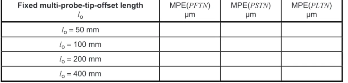
When a multi-probe system is used, the results of these tests are highly dependent on the offset lengths to the stylus tips. A series of tip offset lengths is considered (see Figure 4), all measured from a single point on the ram axis defined by the CMM manufacturer. Only those offset lengths that the CMM manufacturer specifies as applicable to the probing system shall be eligible for test.
Fixed multi-stylus-system stylus length l
MPE(PFTM) µm
MPE(PSTM) µm
MPE(PLTM) µm
l =10 mm
l = 20 mm
l =30 mm
l =50 mm
l =100 mm
l =200 mm
l =400 mm
Figure 3 — Sample fixed multi-stylus probing-system specification sheet
Fixed multi-probe-tip-offset length lo
MPE(PFTN) µm
MPE(PSTN) µm
MPE(PLTN) µm lo= 50 mm
lo = 100 mm lo= 200 mm lo= 400 mm
Figure 4 — Sample fixed multi-probe system specification sheet
Only those stylus or probe-tip-offset lengths applicable to the CMM under consideration should be assigned MPE and MPL values in Figures 3 and 4; non-applicable entries may remain blank.
6.3.2 Measuring equipment
The material standard of size, i.e. the test sphere, shall have a diameter not less than 10 mm and not greater than 50 mm. The test sphere shall be calibrated for size and form.
It is recommended that the form error of the test sphere does not exceed 20 % of PFTM, MPE, or PFTN, MPE, as relevant.
14
© ISO 2010 – All rights reserved The reference sphere supplied with the CMM for probing-system-qualification purposes shall not be used for this test.6.3.3 Procedure
6.3.3.1 When a multi-stylus system is used, construct a “star” stylus system composed of one stylus parallel to the axis of the probe and four styli in a plane perpendicular to the axis, each oriented 90° with respect to those adjacent to it. The distance from the probe to the styli connection point shall be the minimum distance possible (consistent with the manufacturer's recommendations) using the stylus components normally supplied with the CMM (see Figure 5). The applicable values of stylus length, l, shall be equal and specified by the CMM manufacturer, and shall be chosen from the following values: 10 mm, 20 mm, 30 mm, 50 mm, 100 mm, 200 mm and 400 mm (see Figure 3). Only one of the lengths specified by the CMM manufacturer as applicable to the stylus system shall be chosen by the user and tested. The stylus components shall be those approved for use with the CMM probing system, unless otherwise specified. See 5.5 for permitted tolerances on stylus length.
On dual ram CMMs, three of the stylus tips shall be mounted on one ram, and two of the stylus tips on the other ram, all in duplex operating mode (see ISO 10360-2:2009).
Key 1 ram 2 probe
l fixed multi-stylus probing-system length
NOTE For clarity, only four of the five styli and only three shafts are visible.
Figure 5 — Fixed multi-stylus probing system of stylus length l
6.3.3.2 When a multi-probe system is used, attach a short (unless otherwise specified, 20 mm), straight stylus to each of five probes. Assemble them with suitable probe extension components to form a “star” probe system composed of one probe parallel to the axis of the ram and four probes in a plane perpendicular to the axis, each oriented 90° with respect to those adjacent to it. The distances from each of the five stylus tips to a single reference point on the ram axis, the probe-tip-offset lengths, shall all be approximately equal. The applicable values of probe-tip-offset length, lO, shall be specified by the CMM manufacturer, and shall be chosen from the following values: 50 mm, 100 mm, 200 mm and 400 mm (see Figure 4). Only one of the
Copyright British Standards Institution
--`,,```,,,,````-`-`,,`,,`,`,,`---
offset lengths specified by the CMM manufacturer as applicable to the probing system shall be chosen by the user and tested. The probing and stylus components shall be those approved for use with the CMM probing system, unless otherwise specified. However, it is recognized that the exact offset lengths required for the test procedure may not be available, and therefore, a change to the nominal value of the offset length of 6 mm or 10 % of the nominal length, whichever is the greater, may be used.
On dual ram CMMs, three of the probes shall be mounted on one ram, and two of the probes on the other ram, all in duplex operating mode (see ISO 10360-2:2009).
6.3.3.3 The five stylus tips shall not be restricted to a single nominal diameter unless such a restriction is explicit in the CMM manufacturer's specification (see 5.4).
6.3.3.4 Qualify the probing system in accordance with the CMM manufacturer's normal operating procedures.
6.3.3.5 One location of the test sphere shall be chosen by the user anywhere in the measuring volume.
To avoid interference between the probing system and the reference sphere, the reference sphere may be removed from the table during the test.
The test sphere should be mounted rigidly to minimize errors due to bending.
NOTE The location of the test sphere can significantly affect the results. See Annex C for further information.
6.3.3.6 Measure the test sphere using 25 points with each stylus, for a total of 125 points. The points shall be approximately evenly distributed over at least a hemisphere of the test sphere. Their position shall be at the discretion of the user. The recommended point-sampling strategy is the same as for the single-stylus test (6.2).
When the support stalk for the test sphere is located on the vertical centre line and a horizontal stylus is used, then access should be optimized by orienting the probing pattern so that each of the eight points on the equator is at 22,5° to a CMM axis, and the four points in the adjacent plane are at 45° to the Z axis. This is illustrated in Figure 2, if the lower view is considered to be an elevation.
However, if the test sphere is small relative to its support stalk diameter and/or the stylus tip diameter, so that the eight points on the equator cannot be equispaced at 45° over an arc of 315°, then it is recommended that the eight points are equispaced over the available arc.
If a stylus or probe changing system is supplied with the CMM, all five styli shall be qualified, and the styli or probes returned to the rack, before running this test. Five changes shall be performed during the test, each stylus or probe being changed once. However, if fewer than five styli or probe stations are available in the changing system, the maximum number shall be used, with some styli or probes changed more than once to achieve a total of five changes. In the case of a “star” stylus or “star” probe system, the star system shall be returned to the rack and picked up again.
NOTE If the probing-system assembly is identical to that chosen for the single-stylus probing test (see 6.2), there is no need to make the same measurements twice with the one stylus.
6.3.4 Data analysis
6.3.4.1 Associate a least-squares sphere fit for each group of 25 points taken with a single stylus, for a total of five sphere fits. Calculate the range of the centre coordinates (X, Y and Z) of all five spheres. The largest of these three ranges yields the probing-system location value, PLTM or PLTN, as relevant.
6.3.4.2 Associate a least-squares sphere fit for all 125 points taken with all five styli. Record the absolute value of the deviation of the sphere fit diameter from the calibrated value of the material standard of size to give the multi-stylus size error, PSTM or PSTN, as relevant. Similarly, record the range of radii of the 125 points with respect to the least-squares sphere centre, i.e. Rmax − Rmin, the apparent sphere form. The absolute value of this difference is the multi-stylus form error, PFTM or PFTN, as relevant.
--`,,```,,,,````-`-`,,`,,`,`,,`---
16
© ISO 2010 – All rights reserved NOTE According to 6.3.3.3, the five tips are permitted (unless explicitly specified otherwise) to have significantly different nominal diameters, and even when they have the same nominal diameters, generally no two tips will have identical effective diameters. If the CMM software does not correctly handle multiple tip diameters when measuring a single feature, then these five different effective tip diameters may cause increased error values PSTM and PFTM, or PSTN and PFTN, as relevant.6.4 Articulating probing systems
6.4.1 Principle
The principle of these tests is to measure the form, size and location of a test sphere using five different angular positions of an articulating probing system (see Figure 6). At each angular position, 25 points are measured on the test sphere, for a total of 125 points using all five positions.
Key 1 ram
2 articulating probe holder 3 probe extension 4 probe
5 stylus
lA probe-tip-offset length
Figure 6 — Articulating probing system in the vertical position
If a stylus- or probe-changing system is supplied with the CMM, perform five changes, one before each of the angular positions used. Associate a least-squares sphere fit with each group of 25 points taken at each angular position, for a total of five sphere fits.
CMMs with articulating probing systems may use either empirical or inferred qualification data for measurement. Therefore, to prevent ambiguity, the maximum permissible errors and limits for a CMM using empirical qualification are labelled PFTE, MPE, PSTE, MPE and PLTE, MPL, while the maximum permissible errors and limits for a CMM using inferred qualification are labelled PFTI, MPE, PSTI, MPE and PLTI, MPL. Similarly, the errors and values obtained when using empirical qualification are labelled PFTE, PSTE and PLTE, while the errors and values obtained when using inferred qualification are labelled PFTI, PSTI and PLTI.
Copyright British Standards Institution
--`,,```,,,,````-`-`,,`,,`,`,,`---
The ranges of the centre coordinates (X, Y and Z) of all five spheres are calculated. The largest of these three ranges yields the probing-system location value (PLTE or PLTI). In addition, a least-squares sphere fit using all 125 points is examined for the form and size errors of indication. This analysis yields the multi-stylus size error (PSTE or PSTI) and multi-stylus form error (PFTE or PFTI).
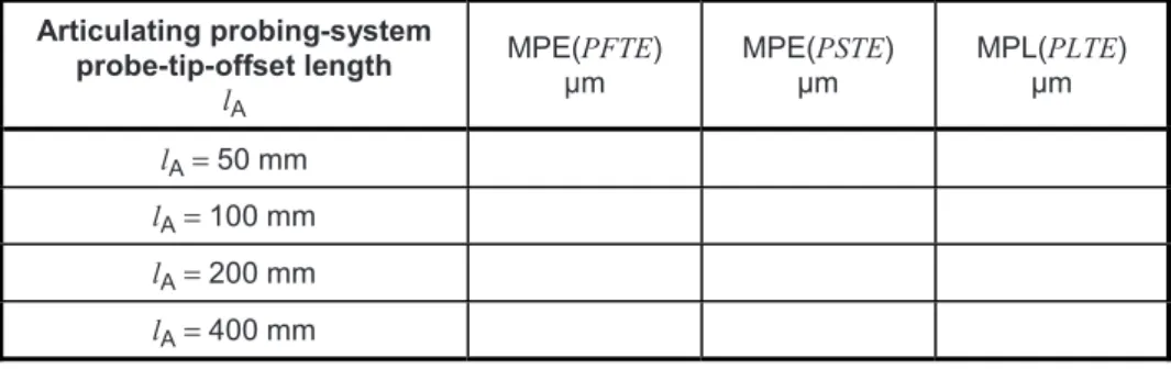
Since the results of these tests are highly dependent on the probe-tip-offset length, a series of tip offset lengths is considered (see Figures 7 and 8), all measured from the centre of rotation of the articulation system.
Only those lengths the CMM manufacturer specifies as applicable to the articulating probing system shall be eligible for test.
Articulating probing-system probe-tip-offset length
lA
MPE(PFTE) µm
MPE(PSTE) µm
MPL(PLTE) µm lA = 50 mm
lA = 100 mm lA = 200 mm lA= 400 mm
Figure 7 — Sample articulating probing-system specification sheet for empirical qualification
Articulating probing-system probe-tip-offset length
lA
MPE(PFTI) µm
MPE(PSTI) µm
MPL(PLTI) µm lA= 50 mm
lA = 100 mm lA = 200 mm lA = 400 mm
Figure 8 — Sample articulating probing-system specification sheet for inferred qualification
Only those probe-tip-offset lengths applicable to the CMM under consideration should be assigned MPE and MPL values in Figures 7 and 8; non-applicable entries may remain blank.
6.4.2 Measuring equipment
The material standard of size, i.e. the test sphere, shall have a diameter not less than 10 mm and not greater than 50 mm. The test sphere shall be calibrated for size and form.
It is recommended that the form error of the test sphere does not exceed 20 % of PFTE, MPE or PFTI, MPE, as relevant.
The reference sphere supplied with the CMM for probing-system qualification purposes shall not be used for this test.
6.4.3 Procedure
6.4.3.1 Attach a short (unless otherwise specified, 20 mm), straight stylus to the probe, then attach them to the articulating probing system with a suitable probe-extension component. The applicable values of probe- tip-offset length, lA, shall be specified by the CMM manufacturer, and shall be chosen from the following values: 50 mm, 100 mm, 200 mm and 400 mm (see Figures 7 and 8). Only one of the offset lengths specified by the CMM manufacturer as applicable to the probing system shall be chosen by the user and tested. The
--`,,```,,,,````-`-`,,`,,`,`,,`---
18
© ISO 2010 – All rights reserved stylus and probe-extension components shall be those approved for use with the CMM probing system, unless otherwise specified.However, it is recognized that the exact probe extension lengths required for the test procedures may not be available, and therefore, a probe-tip-offset length variation of 6 mm or 10 % from the nominal value, whichever is greater, is permitted.
6.4.3.2 When testing for PFTE, MPE, PSTE, MPE and PLTE, MPL is required, qualify the probing system in each of five angular positions in accordance with the CMM manufacturer's normal operating procedures. The five angular positions shall consist of one stylus parallel to the axis of the probe and four styli in a plane perpendicular to the axis, each oriented 90º with respect to those adjacent to it.
On some CMM configurations (e.g. on some horizontal-arm CMMs), some of the above five angular positions may be unattainable or impractical. In such cases, the specified pattern of angular positions should be rotated by ± 90° about either the X or Y axis, as appropriate to the CMM configuration.
On dual ram CMMs, three of the angular positions should be qualified using one ram, and two of the angular positions using the other ram, all in duplex operating mode (see ISO 10360-2:2009).
6.4.3.3 When testing for PFTI, MPE, PSTI, MPE and PLTI, MPL is required, then the qualification of the probing system shall be executed in accordance with the CMM manufacturer's normal operating procedure for inferred qualification. The user shall then choose any five widely spaced angular positions of the articulating probing system for this test.
The user is advised to choose angular test positions for inferred qualification which are remote both from those which were used to qualify the articulating system (if known) and from those which were used to qualify the probing system under test.
On dual ram CMMs, three of the angular positions should be qualified using one ram, and two of the angular positions using the other ram, all in duplex operating mode (see ISO 10360-2:2009).
6.4.3.4 One location of the test sphere shall be chosen by the user anywhere in the measuring volume.
To avoid interference between the probing system and the reference sphere, the reference sphere may be removed from the table during the test.
The test sphere should be mounted rigidly to minimize errors due to bending.
The location of the test sphere can significantly affect the results. See Annex C for further information.
6.4.3.5 Measure the test sphere using 25 points measured in each angular position, for a total of 125 points.
The points shall be approximately evenly distributed over at least a hemisphere of the test sphere. Their position shall be at the discretion of the user. The recommended point-sampling strategy is the same as for the single-stylus test (see 6.2).
When the support stalk for the test sphere is located on the vertical centre line and a horizontal stylus is used, then access should be optimized by orienting the probing pattern so that each of the eight points on the equator is at 22,5° to a CMM axis and the four points in the adjacent plane are at 45° to the Z axis. This is illustrated in Figure 2, if the lower view is considered to be an elevation.
However, if the test sphere is small relative to its support stalk diameter and/or the stylus tip diameter, so that the eight points on the equator cannot be equispaced at 45° over an arc of 315°, then it is recommended that the eight points are equispaced over the available arc.
At least one articulation shall be made after qualification and before measuring the test sphere, for each of the five angular positions.
Copyright British Standards Institution
--`,,```,,,,````-`-`,,`,,`,`,,`---
If a stylus or probe changing system is supplied with the CMM, all five angular positions of the chosen probing-system assembly (6.4.3.1) shall be qualified, and the stylus or probe returned to the rack, before running this test. Five changes shall be performed during the test, the stylus or probe being returned to the rack after measuring the test sphere in each angular position.
NOTE If the probing-system assembly and one of the angular positions are both identical to those chosen for the single-stylus probing test (6.2), there is no need to make the same measurements twice at that angular position.
6.4.4 Data analysis
6.4.4.1 Associate a least-squares sphere fit with each group of 25 points taken at an angular position, for a total of five sphere fits. Calculate the range of the centre coordinates (X, Y and Z) of all five spheres. The largest of these three ranges yields the probing-system location value, PLTE or PLTI, as relevant.
6.4.4.2 Associate a least-squares sphere fit with all 125 points taken with all five angular positions.
Record the absolute value of the deviation of the sphere-fit diameter from the calibrated value of the material standard of size to give the multi-stylus size error PSTE or PSTI, as relevant. Similarly, record the range of radii of the 125 points with respect to the least-squares sphere centre, i.e. Rmax – Rmin, the apparent sphere form.
The absolute value of this difference is the multi-stylus form error, PFTE or PFTI, as relevant.
NOTE Although just one physical stylus tip is used in these tests, the effective diameter of that tip may not be identical in all five angular positions. If the CMM software does not correctly handle multiple tip diameters when measuring a single feature, then these five different effective tip diameters may cause increased PSTE and PFTE, or PSTI and PFTI, error values.
7 Compliance with specification 7.1 Acceptance tests
The single-stylus probing performance is verified if the measured single-stylus form error, PFTU, is not greater than the relevant maximum permissible single-stylus form error, PFTU, MPE, as specified by the manufacturer and taking into account the uncertainty of measurement according to ISO 14253-1.
When relevant, the multi-stylus probing performance is verified if
⎯ the measured multi-stylus form error, PFTj, is not greater than the relevant maximum permissible multi- stylus form error, PFTj, MPE, as specified by the manufacturer and taking into account the uncertainty of measurement according to ISO 14253-1;
⎯ the measured multi-stylus size error, PSTj, is not greater than the relevant maximum permissible multi- stylus size error, PSTj, MPE, as specified by the manufacturer and taking into account the uncertainty of measurement according to ISO 14253-1;
⎯ the measured probing-system location value, PLTj, is not greater than the relevant maximum permissible probing-system location limit, PLTj, MPL, as specified by the manufacturer and taking into account the uncertainty of measurement according to ISO 14253-1.
NOTE Evaluation of test uncertainty is discussed in ISO/TS 23165.
If the performance is not verified by all the relevant tests, all probing equipment shall be thoroughly checked for dust, dirt or any operator-induced faults in stylus-system assembly that could be influencing the measurement result, including the critical issue of ensuring that all probing-system components are in thermal equilibrium. Any faults shall be corrected and the relevant test repeated once only, starting from probing-system qualification and using the same target contact points.
--`,,```,,,,````-`-`,,`,,`,`,,`---
20
© ISO 2010 – All rights reserved7.2 Reverification tests
The single-stylus probing performance is verified if the measured single-stylus form error, PFTU, is not greater than the relevant maximum permissible single-stylus form error, PFTU, MPE, as specified by the user and taking into account the uncertainty of measurement according to ISO 14253-1.
When relevant, the multi-stylus probing performance is verified if
⎯ the measured multi-stylus form error, PFTj, is not greater than the relevant maximum permissible multi- stylus form error, PFTj, MPE, as specified by the user and taking into account the uncertainty of measurement according to ISO 14253-1;
⎯ the measured multi-stylus size error, PSTj, is not greater than the relevant maximum permissible multi- stylus size error, PSTj, MPE