Carbon Dioxide Storage: Geological Security and Environmental Issues – Case Study on the Sleipner Gas field in Norway
(Figure courtesy of Statoil)
Semere Solomon
Bellona Report
May 2007
Table of contents
Table of contents... 1
Executive Summary, Conclusions and Recommendations... 3
1 Introduction ... 7
1.1 Background...7
1.2 Properties of CO2 and Health Effects...9
1.3 Sources of CO2...11
1.4 CO2 Capture and Storage ...11
1.5 Context for CO2 capture and Storage...12
1.6 Potential for reducing CO2 Emissions...12
1.7 Layout of the Report ...13
2 Geological Framework ... 15
2.1 Historical perspectives ...15
2.2 Geological formations ...16
2.2.1 General requirements...17
2.2.2 Saline formations...19
2.3 Geological storage ...19
2.3.1 Effects of impurities ...21
2.3.2 Storage in deep saline formations ...21
2.4 Existing and planned CO2 projects ...22
3 Storage mechanisms and storage security ... 27
3.1 CO2 flow and transport processes ...27
3.2 CO2 storage mechanisms in geological formations ...30
3.2.1 Physical trapping: stratigraphic and structural...30
3.2.2 Physical trapping: hydrodynamic...30
3.2.3 Geochemical trapping...31
3.3 Natural geological accumulations of CO2...32
3.4 Industrial analogues for CO2 storage ...34
3.4.1 Natural gas storage ...34
3.4.2 Acid gas injection...35
3.4.3 Liquid waste injection ...36
3.5 Security and duration of CO2 storage in geological formations ...36
4 Site characterization and performance prediction ... 37
4.1 Site characterization ...37
4.1.1 Data types ...37
4.1.2 Assessment of stratigraphic factors affecting site integrity ...38
4.1.3 Geomechanical factors affecting site integrity ...38
4.1.4 Geochemical factors affecting site integrity ...39
4.1.5 Anthropogenic factors affecting storage integrity...39
4.2 Performance prediction and optimization modelling...40
4.3 Remark ...42
5 Monitoring and verification ... 43
5.1 Purposes for monitoring ...43
5.2 Monitoring ...44
5.2.1 Injection rates and pressures ...44
5.2.2 Subsurface distribution of CO2...44
5.2.3 Injection well integrity...46
5.2.4 Local environmental effects...46
5.2.5 Network design and duration ...48
5.3 Verification of CO2 injection and storage inventory ...49
6 Risk assessment, management, and remediation... 51
6.1 Frameworks for assessing environmental risks ...51
6.2 Processes and pathways for release of CO2 from geological storage sites ...52
6.3 Risk assessment methodology ...54
6.4 Probability of release from geological storage sites ...56
6.4.1 Natural systems ...57
6.4.2 Engineered systems ...57
6.4.3 Fate of CO2 in the subsurface ...58
6.4.4 Numerical simulations of long-term storage performance ...58
6.4.5 Assessment of underground CO2 retention...59
6.5 Possible local and regional environmental hazards ...59
6.5.1 Potential hazards to human health and safety ...59
6.5.2 Hazards to groundwater from CO2 leakage and brine displacement ...60
6.5.3 Hazards to terrestrial and marine ecosystems...61
6.5.4 Induced seismicity...62
6.5.5 Implications of gas impurity ...63
6.6 Risk management...64
6.7 Remediation of leaking storage projects ...64
7 Knowledge gaps ... 67
8 Case study - The Sleipner Gas field... 69
8.1 Background...69
8.1.1 Offshore geology...69
8.1.2 Utsira Formation ...71
8.1.3 Saline Aquifer Carbon dioxide Storage (SACS) Project...73
8.1.4 CO2 storage quality and capacity ...74
8.2 Geological Suitability...74
8.3 Tasks accomplished ...75
8.3.1 Micoseismic studies ...75
8.3.2 Characterisation of the reservoir ...76
8.3.3 Characterisation of caprocks...79
8.3.4 Monitoring the injection process...81
8.3.5 Integration of time-lapse seismic with reservoir flow model ...84
8.3.6 Reservoir simulation in SACS: Verifying the seismic and geological interpretations and predicting the long-term fate of CO2...85
8.3.7 Calibration of a local reservoir model by use of repeated 3D seismic...85
8.3.8 Simulation of the long-term fate of CO2 in a large-scale model ...87
8.3.9 Assessing the geochemical effects of CO2 injection ...91
8.3.10 Determination of the geochemical impact of injected CO2...92
8.3.11 Assessment of monitoring techniques ...95
8.4 Summary of recent studies ...97
8.5 Geological security ...101
8.6 Environmental issues ...102
8.7 Conclusions ...103
8.8 Recommendations...104
Acknowledgements ... 105
References: ... 107
Executive Summary, Conclusions and Recommendations
Executive Summary
Carbon dioxide capture and storage (CCS) is one option for mitigating atmospheric emissions of carbon dioxide and thereby contributes in actions for stabilization of atmospheric greenhouse gas concentrations. The Bellona Foundation is striving to achieve wide implementation of carbon dioxide (CO2) capture and storage both in Norway and internationally. Bellona considers CCS as the only viable large scale option to close the gap between energy production and demand in an environmentally sound way, thereby ensuring that climate changes and acidification of the oceans due to increased CO2 concentrations in the atmosphere will be stabilised.
Carbon dioxide storage in geological formations has been in practice since early 1970s.
Information and experience gained from the injection and/or storage of CO2 from a large number of existing enhanced oil recovery (EOR) and acid gas projects, as well as from the Sleipner, Weyburn and in Salah projects, indicate that it is feasible to store CO2 in geological formations as a CO2 mitigation option. Industrial analogues, including underground natural gas storage projects around the world and acid gas injection projects, provide additional indications that CO2 can be safely injected and stored at well-characterized and properly managed sites. Injection of CO2 in deep geological formations uses technologies that have been developed for, and applied by, the oil and gas industry to meet the needs of geological storage. While there are differences between natural accumulations and engineered storage, injecting CO2 into deep geological formations at carefully selected sites can store it underground for long periods of time.
Saline formations (deep underground porous reservoir rocks saturated with brackish water or brine), can be used for storage of CO2. At depths below about 800–1000 m, CO2 has a liquid- like density that provides the potential for efficient utilization of underground storage space in the pores of sedimentary rocks. Carbon dioxide can be trapped underground by various storage mechanisms, such as: trapping below an impermeable, confining layer (caprock);
retention as an immobile phase trapped in the pore spaces of the storage formation; and/or dissolved in the in situ formation fluids. Additionally, it may be trapped by reacting with the minerals in the storage formation and caprock to produce carbonate minerals. CO2 becomes less mobile over time as a result of multiple trapping mechanisms, further lowering the prospect of leakage, which builds the confidence in geological security of carbon dioxide storage.
Site characterization is a prerequisite to safe geological storage of CO2. Key goals for geological CO2 storage site characterization are to assess how much CO2 can be stored at a potential storage site and to demonstrate that the site is capable of meeting required storage performance criteria. Site characterization requires the collection of the wide variety of geological data that are needed to achieve these goals. Much of the data will necessarily be site-specific. Most data will be integrated into geological models that will be used to simulate and predict the performance of the site. Performance prediction of a site can be made using models that are available to predict what happens when CO2 is injected underground. Also, by avoiding deteriorated wells or open fractures or faults, injected CO2 will be retained for very long periods of time.
Monitoring is needed for a wide variety of purposes and monitoring methods can potentially be adapted from existing applications to meet the needs of geological storage. Specifically, to ensure and document the injection process, verify the quantity of injected CO2 that has been stored by various mechanisms, demonstrate with appropriate monitoring techniques that CO2
remains contained in the intended storage formation(s). This is currently the principal method for assuring that the CO2 remains stored and that performance predictions can be verified.
Finally monitoring is required to detect leakage and provide an early warning of any seepage or leakage that might require mitigating action and to assess environmental effects. Potential risks to humans and ecosystems from geological storage may arise from leaking injection wells, abandoned wells, and leakage across faults and ineffective confining layers. Leakage of CO2 could potentially degrade the quality of groundwater, damage some hydrocarbon or mineral resources, and have lethal effects on plants and sub-soil animals. Release of CO2 back into the atmosphere could also create local health and safety concerns. Avoiding or mitigating these impacts will require careful site selection, effective regulatory oversight, an appropriate monitoring programme that provides early warning that the storage site is not functioning as anticipated and implementation of remediation methods to stop or control CO2 releases.
Methods to accomplish these are being developed and tested. There are gaps in our knowledge, such as regional storage capacity estimates for many parts of the world. Similarly, better estimation of leakage rates, improved cost data, better intervention and remediation options, more pilot and demonstration projects and clarity on the issue of long-term stewardship all require consideration. Despite the fact that more work is needed to improve technologies and decrease uncertainty, there appear to be no insurmountable technical barriers to an increased uptake of geological storage as an effective mitigation option.
Geological storage of CO2 is in practice today beneath the North Sea, where nearly 1 MtCO2
has been successfully injected annually in the Utsira formation at Sleipner since 1996. It is an ideal CO2 storage site typical of deep saline sedimentary formation. The site is well characterized and the CO2 injection process was monitored using seismic methods and this provided insights into the geometrical distribution of the injected CO2 and provided increased understanding of the CO2 migration within the reservoir. Performance prediction of the site shows that most of the CO2 accumulates in one bubble under the cap seal of the formation controlled by the topography of the cap seal only. In the long term (> 50 years) the phase behaviour (solubility and density dependence of composition) will become the controlling fluid parameters at Sleipner. The solubility trapping has the effect of eliminating the buoyant forces that drive CO2 upwards and through time can lead to mineral trapping, which is the most permanent and secure form of geological storage. Recent studies at Sleipner area demonstrate further the geological security of carbon dioxide storage and the monitoring tools (Gravity and Seismic methods) strengthen verification of safe injection of CO2 in the Utsira formation. Subsequent work in the following years is necessary to reinforce these findings further that CO2 storage is safe through monitoring and verification procedures that will be able to detect potential leaks.
Conclusions
The security of carbon dioxide storage in geological formations first and foremost depends on careful storage site selection followed by characterization of the selected site in terms of geology, hydrogeology, geochemistry and geomechanics (structural geology and deformation in response to stress changes). The Utsira Formation is well characterized with respect to porosity and permeability (good storage capacity and injectivity), mineralogy, bedding, depth, pressure and temperature. It is a very large aquifer with a thick and extensive clay stone top
seal. Available geological information shows absence of major tectonic events after the deposition of the Utsira formation. This means that the geological environment is tectonically stable which implies that the site is suitable for carbon dioxide storage. Microseismic studies suggest the injection of CO2 in sands of the Utsira Formation has not trigged any measurable microseismicity. This further builds the confidence in geological security of carbon dioxide storage at Sleipner. Moreover, evidence from ten years experience of carbon dioxide storage shows no leakages.
The Sleipner project is a commercial CO2 injection project and proved that CO2 capture and storage is a technically feasible and effective method for greenhouse mitigation. It further demonstrates that CO2 storage is both safe and has a low environmental impact. Monitoring is needed for a wide variety of purposes. Specifically, to ensure and document the injection process, verify the quantity of injected CO2 that has been stored by various mechanisms, demonstrate with appropriate monitoring techniques that CO2 remains contained in the intended storage formation(s). This is currently the principal method for assuring that the CO2
remains stored and that performance predictions can be verified. Finally monitoring is required to detect leakage and provide an early warning of any seepage or leakage that might require mitigating action and to assess environmental effects. The work that has been undertaken at Sleipner Gas Field has shown that the injected CO2 can be monitored within a geological storage reservoir, using seismic surveying. The geochemical and reservoir simulation work have laid the foundations to show how the CO2 has reacted and what its long term fate in the reservoir will be. The results of the simulations indicate that most of the CO2 accumulates in a stack of accumulations under thin clay layers interbedded in the sand unit few years after the injection is turned off. The CO2 plume spreads laterally on top of the brine column and the migration is controlled by the interbedded thin clay layers within the sand unit. In the long term (> 50 years) the phase behaviour (solubility and density dependence of composition) will become the controlling fluid parameters at Sleipner. The solubility trapping has the effect of eliminating the buoyant forces that drive CO2 upwards and through time can lead to mineral trapping, which is the most permanent and secure form of geological storage.
The recent studies at Sleipner area reveal the integrity of the cap rock (efficient sealing capacity). The injected CO2 will potentially be trapped geochemically and the regional groundwater flow having an effect on the distribution of CO2 with the potential of pressure build up as a result of CO2 injection is unlikely to occur. Monitoring techniques (both Time- lapse Gravity and Seismic methods) proved to be key tools in understanding the whole- reservoir performance. Overall, the recent studies at Sleipner area demonstrate further the geological security of carbon dioxide storage and the monitoring tools strengthen verification of safe injection of CO2 in the Utsira formation. Subsequent work in the following years is necessary to reinforce these findings further that CO2 storage is safe through monitoring and verification procedures that will be able to detect potential leaks.
Recommendations
Several CO2 storage projects are now in operation and being carefully monitored. No leakage of stored CO2 out of the storage formations has been observed in any of the current projects.
Although time is too short to enable direct empirical conclusions about the long-term performance of geological storage, it is an indication that CO2 can be safely injected and stored at well characterized and properly managed sites. Monitoring of existing projects in the coming 10-20 years is crucial to the broader understanding of CO2 transport, trapping mechanisms and storage security and to predict long-duration performance. However, if leaks
occur, tools for monitoring possible local and regional environmental hazards should be in place together with remediation measures. In this section general recommendations which are thought to contribute to better understanding of geological storage of CO2 with regard to security and environmental safety. Also the measures needed to be taken in future are listed below.
1) Storage capacity determination for large scale carbon dioxide storage should be determined as accurately as possible. The problem of heterogeneity and porosity should be assessed carefully. Reaction of the CO2 with formation water and rocks may result in reaction products that affect the porosity of the rock and the flow of solution through the pores. This possibility has not been observed experimentally and its possible effects are not quantified. It is important to assess these effects to get better knowledge about the reservoir and migration patterns of the injected CO2.
2) During site characterization greatest emphasis are placed on the reservoir and its sealing horizons. However, the strata above the storage formation and caprock also need to be assessed because if CO2 leaked it would migrate through them.
3) Geological storage projects will be selected and operated to avoid leakage. However, in rare cases, leakage may occur and remediation measures will be needed, either to stop the leak or to prevent human or ecosystem impact. Moreover, the availability of remediation options may provide an additional level of assurance to the public that geological storage can be safe and effective. Therefore appropriate remediation options must be identified in an event of a leakage scenario.
4) The Utsira Formation is a very large aquifer with a thick and extensive claystone top seal. The aquifer is, however, unconfined along its margins. It is important to assess the time required for the migrating CO2 to reach at the margins of the aquifer.
5) To predict the migration of CO2 over a period of several thousand years a coarse grid model was used due to computational constraints. However, grid patterns may miss narrow linear anomalies or patterns of linear features on the surface that may reflect deeper fault and fracture systems, which could become natural migration pathways.
Future modelling should account such uncertainties.
6) During the SACS project (Best Practice Manual, 2004), the lack of observation boreholes and related samples made it impossible to monitor directly the geochemical processes occurring within the Utsira at Sleipner. Also the interactions of CO2 with borehole cement were not addressed in the study. Assessment of both issues should be a priority in future monitoring activities.
7) Evaluations on the risk of leakage through injection well, seal, and stress release events due to injection of CO2 and their probabilities on the release of CO2 should be a priority. Moreover, quantification of the short-term and long-term Health-Safety- Environmental (HSE) risks, in this case the likelihood of impacts on human and marine life should be assessed.
8) Finally further research on the processes involved in both sealing and in migration of CO2 in the underground and improved modelling tools is needed to predict future behaviour of a storage location. Modelling tools need to be improved through calibration on real life experiments. Demonstration under different geological conditions is also pointed as important both for improving the understanding but also to prove to the public that storage are safe.
1 Introduction
1.1 Background
Carbon dioxide capture and storage (CCS) is one option for mitigating atmospheric emissions of carbon dioxide thereby contributes in actions for stabilization of atmospheric greenhouse gas concentrations. The Bellona Foundation is striving to achieve wide implementation of CO2 capture and storage both in Norway and internationally. Bellona considers CO2 capture and storage as the only viable large scale option to close the gap between energy production and demand in an environmentally sound way, thereby ensuring that climate changes and acidification of the oceans due to increased CO2 concentrations in the atmosphere will be stabilised. CCS has the potential to reduce overall mitigation costs and increase flexibility in achieving greenhouse gas emission reductions. The widespread application of CCS would depend on technical maturity, costs, overall potential, diffusion and transfer of the technology to developing countries and their capacity to apply the technology, regulatory aspects, environmental issues and public perception.
The greenhouse gas (GHG) making the largest contribution to atmospheric emissions from human activities is carbon dioxide (CO2). It is released by burning fossil fuels and biomass as a fuel; from the burning, for example, of forests during land clearance; and by certain industrial and resource extraction processes. Emissions of CO2 due to fossil fuel burning are the dominant influence on the trends in atmospheric CO2 concentration because according to the International Energy Agency (IEA) 80 % of the global energy consumption is based on coal, oil, and natural gas (IEA, 2005). Global average temperatures and sea level are projected to rise if appropriate measures are not taken. Due to increased emissions of GHG, the global average temperature will increase by 1.4 to 5.8 oC from 1990 to 2100, according to The Intergovernmental Panel on Climate Change (IPCC, 2001c). The increase in global temperature will have dramatic impacts on life on earth. If no action is taken, the sea level will increase with up to one meter within 2100. One consequence of a one meter rise in sea level is that 40 % of Bangladesh will be under water. Other effects of global warming include increasing precipitation, increased frequency of extreme climate events, disrupting ecosystems, and extinction of species (Wiliams, 2002). Steps should be taken that aim in the stabilization of greenhouse gas concentrations in the atmosphere at a level that would prevent dangerous anthropogenic interference with the climate system.
Several technological options for reducing net CO2 emissions to the atmosphere exist (IPCC, 2005). These include energy efficiency improvements, the switch to less carbon-intensive fuels, nuclear power, renewable energy sources, enhancement of biological sinks, reduction of non-carbon dioxide greenhouse gas emissions and capture and store CO2 chemically or physically. A variety of factors will need to be taken into account in any comparisons of these mitigation options. The factors include the potential of each option to deliver emission reductions, the national resources available, the accessibility of each technology for the country concerned, national commitments to reduce emissions, the availability of finance, public acceptance, likely infrastructural changes, environmental side-effects, etc. (IPCC, 2005). The IPCC (2001a) found that improvements in energy efficiency have the potential to reduce global CO2 emissions by 30% using existing technologies. However, on their own, efficiency gains are unlikely to be sufficient, or economically feasible, to achieve deep
reductions in emissions of GHGs (IPCC, 2001a). Wider use of renewable energy sources was also found to have substantial potential. Nonetheless, many of the renewable sources face constraints related to cost, intermittency of supply, land use and other environmental impacts (IPCC, 2005). Carbon dioxide capture and storage can be a good option because it can be implemented on a larger scale and has also the potential capacity for deep emission reduction.
The Bellona Foundation believes that actions have to be taken now in order to avoid dramatic future climate changes. There is a need for short-term strategies for ensuring energy production with the lowest GHG emissions possible, and the best strategy is to establish carbon capture sequestration (Stangeland et al., 2006). Energy production from fossil fuel power plants combined with CO2 handling including CO2 capture, transport and safe storage will minimize GHG emissions.
There are three main components of the CCS process: capturing CO2, for example by separating it from the flue gas stream of a fuel combustion system and compressing it to a high pressure; transporting it to the storage site; and storing it. CO2 storage will need to be done in quantities of gig tonnes of CO2 per year to make a significant contribution to the mitigation of climate change. Globally there is a potential of 240 billion ton CO2 to be captured and stored by 2050 (Stangeland, 2006). This corresponds to a 37 % reduction in global CO2 emissions in 2050 compared to emissions today. Several types of storage reservoir may provide storage capacities of this magnitude. In some cases, the injection of CO2 into oil and gas fields could lead to the enhanced production of hydrocarbons, which would help to offset the cost due to the increased income from the increased product. CO2 capture technology could be applied to fossil-fuelled power plants and other large industrial sources of emissions; it could also be applied in the manufacture of hydrogen as an energy carrier.
Most stages of the CCS process build on known technology developed for other purposes.
There are many factors that must be considered when deciding what role CO2 capture and storage could play in mitigating climate change. These include the cost and capacity of emission reduction relative to, or in combination with other options such as energy efficiency improvements, the switch to less carbon-intensive fuels, nuclear power, renewable energy sources, enhancement of biological sinks or reduction of non-carbon dioxide greenhouse gas emissions; the resulting increase in demand for primary energy sources; the range of applicability; and the technical risk. Other important factors are the social and environmental consequences, the safety of the technology, the security of storage and ease of monitoring and verification, and the extent of opportunities to transfer the technology to developing countries.
Many of these features are interlinked. Some aspects are more amenable to rigorous evaluation than others. For example, the literature about the societal aspects of this new mitigation option is limited. Public attitudes, which are influenced by many factors, including how judgements are made about the technology, will also exert an important influence on its application. Of all these aspects, the security of the storage, assessment of monitoring and verification techniques, and environmental considerations are the main topics discussed in this report. The report analyzes the current state of knowledge about the scientific and technical dimensions of CCS option with emphasis on geological storage, security and environmental impacts. This report reviews literature published on geological storage of carbon dioxide in deep saline aquifers with emphasis on the Sleipner Gas field project in Norway.
1.2 Properties of CO2 and Health Effects
Carbon dioxide is a chemical compound of two elements, carbon and oxygen, in the ratio of one to two; its molecular formula is CO2. It is present in the atmosphere in small quantities (370 ppmv) and plays a vital role in the Earth’s environment as a necessary ingredient in the life cycle of plants and animals. During photosynthesis plants assimilate CO2 and release oxygen. Anthropogenic activities which cause the emission of CO2 include the combustion of fossil fuels and other carbon containing materials, the fermentation of organic compounds such as sugar and the breathing of humans. Natural sources of CO2; including volcanic activity, dominate the Earth’s carbon cycle. CO2 gas has a slightly irritating odour, is colourless and is denser than air. At normal temperature and pressure, carbon dioxide is a gas.
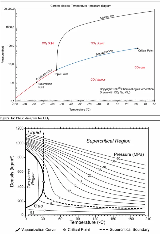
The physical state of CO2 varies with temperature and pressure as shown in Figure 1a − at low temperatures CO2 is a solid; on warming, if the pressure is below 5.1 bar, the solid will sublime directly into the vapour state. At intermediate temperatures (between −56.5oC, the temperature of the triple point, and 31.1oC, the critical point), CO2 may be turned from a vapour into a liquid by compressing it to the corresponding liquefaction pressure (and removing the heat produced). At temperatures higher than 31.1oC (if the pressure is greater than 73.9 bar, the pressure at the critical point), CO2 is said to be in a supercritical state where it behaves as a gas; indeed under high pressure, the density of the gas can be very large, approaching or even exceeding the density of liquid water (also see Figure 1b). This is an important aspect of CO2’s behaviour and is particularly relevant for its storage. In an aqueous solution CO2 forms carbonic acid, which is too unstable to be easily isolated. The solubility of CO2 in water decreases with increasing temperature and increases with increasing pressure.
The solubility of CO2 in water also decreases with increasing water salinity.
As a normal constituent of the atmosphere, where it is present in low concentrations (currently 370 ppmv or 0.037%), CO2 is considered harmless. CO2 is non-flammable. As it is 1.5 times denser than air at normal temperature and pressure, there will be a tendency for any CO2
leaking from pipe work or storage to collect in hollows and other low-lying confined spaces which could create hazardous situations. The hazardous nature of the release of CO2 is enhanced because the gas is colourless, tasteless and is generally considered odourless unless present in high concentrations. When contained under pressure, escape of CO2 can present serious hazards, for example asphyxiation, noise level (during pressure relief), frostbite, hydrates/ice plugs and high pressures (Jarrell et al., 2002). The handling and processing of CO2 must be taken into account during the preparation of a health, safety and environment plan for any facility handling CO2.
Most people with normal cardiovascular, pulmonary-respiratory and neurological functions can tolerate exposure of up to 0.5−1.5% CO2 for one to several hours without harm. Higher concentrations or exposures of longer duration are hazardous – either by reducing the concentration of oxygen in the air to below the 16% level required to sustain human life, or by entering the body, especially the bloodstream, and/or altering the amount of air taken in during breathing; such physiological effects can occur faster than the effects resulting from the displacement of oxygen, depending on the concentration of CO2. Longer exposure, even to less than 1% concentration, may significantly affect health. Noticeable effects occur above this level, particularly changes in respiration and blood pH level that can lead to increased heart rate, discomfort, nausea and unconsciousness.
Figure 1a: Phase diagram for CO2.
Figure 1b: Variation of CO2 density as a function of temperature and pressure (Bachu, 2003).
Acute exposure to CO2 concentrations at or above 3% may significantly affect the health of the general population. Hearing loss and visual disturbances occur above 3% CO2. Signs of asphyxia will be noted when atmospheric oxygen concentration falls below 16%.
Unconsciousness, leading to death, will occur when the atmospheric oxygen concentration is reduced to ≤ 8% although, if strenuous exertion is being undertaken, this can occur at higher oxygen concentrations (Rice, 2004). CO2 acts as an asphyxiant in the range 7−10% and can be fatal at this concentration; at concentrations above 20%, death can occur in 20 to 30 minutes (Fleming et al., 1992). Health risks to the population could therefore occur if a release of CO2 were to produce:
• relatively low ambient concentrations of CO2 for prolonged periods;
• or intermediate concentrations of CO2 in relatively anoxic environments;
• or high concentrations of CO2.
1.3 Sources of CO
2The main source of anthropogenic carbon dioxide (CO2) emission is the combustion of fossil fuels. Other sources are combustion of biomass-based fuels in certain industrial processes, such as the production of hydrogen, ammonia, iron and steel, or cement. Studies show that the power and industry sectors combined dominate current global CO2 emissions, accounting for about 60% of total CO2 emissions (IEA, 2003). The CO2 emissions in these sectors are generated by boilers and furnaces burning fossil fuels and are typically emitted from large exhaust stacks. Typical examples are large industrial complexes like power plants and refineries with multiple exhaust stacks. These stacks can be described as large stationary sources, to distinguish them from mobile sources such as those in the transport sector and from smaller stationary sources such as small heating boilers used in the residential sector.
1.4 CO
2Capture and Storage
Carbon dioxide (CO2) capture and storage (CCS) is a process consisting of the separation of CO2 from large industrial and energy-related sources, transport to a storage location and long- term isolation from the atmosphere. Capturing CO2 involves separating the CO2 from some other gases such as for example, in the flue gas stream of a power plant, the other gases are mainly nitrogen and water vapour. The CO2 must then be transported to a storage site where it will be stored away from the atmosphere for a very long time (IPCC, 2001a). In order to have a significant effect on atmospheric concentrations of CO2, storage reservoirs would have to be large relative to annual emissions. Available storage sites have large capacity compared to emitted volumes. The large stationary sources represent potential opportunities for the addition of CO2 capture plants. The volumes produced from these sources are usually large and the plants can be equipped with a capture plant to produce a source of high-purity CO2 for subsequent storage. Of course, not all power generation and industrial sites produce their emissions from a single point source. At large industrial complexes like refineries there will be multiple exhaust stacks, which present an additional technical challenge in terms of integrating an exhaust-gas gathering system in an already congested complex, undoubtedly adding to capture costs (Simmonds et al., 2003).
1.5 Context for CO
2capture and Storage
CO2 emissions continued an upward trend in the early years of the 21st century. Fossil fuels are the dominant form of energy utilized in the world (86%), and account for about 75% of current anthropogenic CO2 emissions (IPCC, 2001c). In 2002, 149 Exajoules (EJ) of oil, 91 EJ of natural gas, and 101 EJ of coal were consumed globally (IEA, 2004). Global primary energy consumption grew at an average rate of 1.4% annually between 1990 and 1995; and 1.6% per year between 1995 and 2001. The growth rates by sector are given in Table-1.
Average global CO2 emissions increased by 1.0% per year between 1990 and 1995 and 1.4%
between 1995 and 2001 a rate slightly below that of energy consumption in both periods. In individual sectors, there was no increase in emissions from industry between 1990 and 1995;
there was an increase of emissions in other sectors except in the agricultural/other sector where a fall of emission was noted (Table-1).
Total emissions from fossil fuel consumption and flaring of natural gas were 24 GtCO2 per year (6.6 GtC per year) in 2001 – industrialized countries were responsible for 47% of energy-related CO2 emissions (not including international bunkers). The Economies in Transition1 accounted for 13% of 2001 emissions; emissions from those countries have been declining at an annual rate of 3.3% per year since 1990. Developing countries in the Asia- Pacific region emitted 25% of the global total of CO2; the rest of the developing countries accounted for 13% of the total (IEA, 2003).
Table-1: Global energy consumption growth rates and average global CO2 emissionsby sectors (IEA, 2003).
Global energy consumption growth rate %
Average Global CO2 emissions
% Sector
1990-1995 1995-2001 1990-1995 1995-2001
Industrial sector
0.3 0.9 0.0 0.9
Transportation sector
2.1 2.2 1.7 2.0
Building sector 2.7 2.1 2.3 2.0
Agricultural and other sectors
-2.4 -0.8 -2.8 -1.0
1.6 Potential for reducing CO
2Emissions
It has been determined (IPCC, 2001a) that the worldwide potential for GHG emission reduction by the use of technological options amounts to between 6,950 and 9,500 MtCO2 per year (1,900 to 2,600 MtC per year) by 2010, equivalent to about 25 to 40% of global emissions respectively. The potential rises to 13,200 to 18,500 MtCO2 per year (3,600 to 5,050 MtC per year) by 2020. The evidence on which these estimates are based is extensive but has several limitations: for instance, the data used comes from the 1990s and additional new technologies have since emerged. In addition, no comprehensive worldwide study of
technological and economic potential has yet been performed; regional and national studies have generally had different scopes and made different assumptions about key parameters (IPCC, 2001a). Globally, a 37 % reduction in CO2 emissions by mid century compared to emissions today can be achieved. The accumulated CO2 captured and stored globally can reach up to 240 billion ton CO2 by 2050 (Stangeland, 2006).
IPCC’s Third Assessment Report (IPCC, 2001b) found that the option for reducing emissions with most potential in the short term (up to 2020) was energy efficiency improvement while the near-term potential for CO2 capture and storage was considered modest, amounting from 73 to 183 MtCO2 per year (20 to 50 MtC per year) from coal and a similar amount from natural gas (see IPCC 2001a, Table TS.1). To meet IPCC’s target on 50-80 % CO2 emission reduction by 2050, a combination of increasing energy efficiency, switching from fossil fuel to renewable energy sources, and wide implementation of CCS is necessary (Stangeland, 2006). Nevertheless, faced with the longer-term climate challenge described above, and in view of the growing interest in this option, it has become important to analyze the potential of this technology in more depth.
As a result of the 2002 IPCC workshop on CO2 capture and storage (IPCC, 2002), it is now recognized that the amount of CO2 emissions which could potentially be captured and stored may be higher than the value given in the Third Assessment Report (ICPP, 2005). Indeed, the emissions reduction may be very significant compared with the values quoted above for the period after 2020. Wider use of this option may tend to restrict the opportunity to use other energy supply options. Nevertheless, such action might still lead to an increase in emissions abatement because much of the potential estimated previously (IPCC, 2001a) was from the application of measures concerned with end uses of energy. Some applications of CCS cost relatively little (for example, storage of CO2 from gas processing as in the Sleipner project (Baklid et al., 1996)) and this could allow them to be used at a relatively early date. Certain large industrial sources could present interesting low-cost opportunities for CCS, especially if combined with storage opportunities which generate compensating revenue, such as CO2
Enhanced Oil Recovery (EOR) (IEA GHG, 2002).
1.7 Layout of the Report
This report is organized into eight chapters. Brief introduction with background information about the grounds on carbon dioxide (CO2) capture and storage including the properties and health effects and sources of CO2 as well as the context for capture and storage together with the potential for reducing atmospheric emissions is highlighted in this chapter. Chapter 2 gives detail on the geological framework for CO2 storage. In this chapter, the historical perspectives of geological storage of CO2, geological formations in general and the requirements in deep saline formations in particular with current and future geological storage projects are highlighted. Chapter 3 examines the geological storage mechanisms and storage security. Injection of CO2 into the pore space and fractures of a permeable geological formation can displace the in situ fluid or the CO2 may dissolve in or mix with the fluid or react with the mineral grains or there may be some combination of these processes. This chapter examines these processes and their influence on geological storage of CO2. Site characterization and performance prediction are the topics covered in Chapter 4.
1Economy in transition is an economy which is changing from a planned economy to a free market.
Key goals for geological CO2 storage site characterization are to assess how much CO2 can be stored at a potential storage site and to demonstrate that the site is capable of meeting required storage performance criteria. Site characterization requires the collection of the wide variety of geological data that are needed to achieve these goals. Much of the data will necessarily be site-specific. Most data will be integrated into geological models that will be used to simulate and predict the performance of the site. These and related issues are considered in chapter four in this report.
Chapter 5, details the monitoring and verification aspects of a geological CO2 storage site.
What actually happens to CO2 in the subsurface and how do we know what is happening? In other words, can we monitor CO2 once it is injected? What techniques are available for monitoring whether CO2 is leaking out of the storage formation and how sensitive are they?
Can we verify that CO2 is safely and effectively stored underground? How long is monitoring needed? These questions are addressed in Chapter 5 of the report. Risk assessment, management and remediation of geological CO2 storage are discussed in Chapter 6. What are the risks of storing CO2 in deep geological formations? Can a geological storage site be operated safely? What are the safety concerns and environmental impact if a storage site leaks? Can a CO2 storage site be fixed if something does go wrong? These questions are addressed in this chapter. After reviewing the current state of knowledge, the existing gaps in knowledge are also outlined.
The existing gaps in knowledge on the geological storage of CO2 are detailed in Chapter 7. In Chapter 8 a case study from the Sleipner Gas field in Norway is presented. Background studies, geological suitability of the deep saline aquifer carbon dioxide storage and the tasks accomplished during the two phases of the Saline Aquifer Carbon dioxide Storage (SACS1/2) projects are detailed. Summary of recent studies at Sliepner, the geological security and environmental issues are also discussed in this chapter. Finally, these are followed by the conclusions drawn and the recommendations made from the study.
2 Geological Framework
2.1 Historical perspectives
Geological storage of CO2 provide a way to avoid emitting CO2 into the atmosphere, by capturing CO2 from major stationary sources, transporting it usually by pipeline and injecting it into suitable deep rock formations. The subsurface is the Earth’s largest carbon reservoir, where the vast majority of the world’s carbon is held in coals, oil, gas organic-rich shales and carbonate rocks. Geological storage of CO2 has been a natural process in the Earth’s upper crust for hundreds of millions of years. Carbon dioxide derived from biological activity, igneous activity and chemical reactions between rocks and fluids accumulates in the natural subsurface environment as carbonate minerals, in solution or in a gaseous or supercritical form, either as a gas mixture or as pure CO2.
The engineered injection of CO2 into subsurface geological formations was first undertaken in Texas, USA, in the early 1970s, as part of enhanced oil recovery (EOR) projects and has been ongoing there and at many other locations ever since. Geological storage of anthropogenic CO2 as a greenhouse gas mitigation option was first proposed in the 1970s, but little research was done until the early 1990s, when the idea gained credibility through the work of individuals and research groups (Marchetti, 1977; Baes et al., 1980; Kaarstad, 1992; Koide et al., 1992; van der Meer, 1992; Gunter et al., 1993; Holloway and Savage, 1993; Bachu et al., 1994; Korbol and Kaddour, 1994). The subsurface disposal of acid gas (a by-product of petroleum production with a CO2 content of up to 98%) in the Alberta Basin of Canada and in the United States provides additional useful experience. In 1996, the world’s first large-scale storage project was initiated by Statoil and its partners at the Sleipner Gas Field in the North Sea.
By the late 1990s, a number of publicly and privately funded research programmes were under way in the United States, Canada, Japan, Europe and Australia. Throughout this time, though less publicly, a number of oil companies became increasingly interested in geological storage as a mitigation option, particularly for gas fields with a high natural CO2 content such as Natuna in Indonesia, In Salah in Algeria and Gorgon in Australia. More recently, coal mining companies and electricity-generation companies have started to investigate geological storage as a mitigation option of relevance to their industry.
In a little over a decade, geological storage of CO2 has grown from a concept of limited interest to one that is quite widely regarded as a potentially important mitigation option. There are several reasons for this. First, as research has progressed and as demonstration and commercial projects has been successfully undertaken, the level of confidence in the technology has increased. Second, there is consensus that a broad portfolio of mitigation options is needed. Third, geological storage (in conjunction with CO2 capture) could help to make deep cuts to atmospheric CO2 emissions. However, if that potential is to be realized, the technique must be safe, environmentally sustainable, cost-effective and capable of being broadly applied.
2.2 Geological formations
Geological storage of CO2 can be undertaken in a variety of geological settings in sedimentary basins. Within these basins, oil fields, depleted gas fields, deep coal seams and saline formations are all possible storage formations (Figure 2). Subsurface geological storage is possible both onshore and offshore, with offshore sites accessed through pipelines from the shore or from offshore platforms. The continental shelf (Figure 3) and some adjacent deep- marine sedimentary basins are potential offshore storage sites, but the majority of sediments of the abyssal deep ocean floor (extreme right in Figure 3) are too thin and impermeable to be suitable for geological storage (Cook and Carleton, 2000). In addition to storage in sedimentary formations, some other geological formations which may serve as storage sites include caverns, basalt and organic-rich shales. In this study emphasis is given to deep saline aquifer formations (Section 2.2.2). Readers are referred to details in other geological formations in IPCC, 2005 report.
Figure 2: Options for storing CO2 in deep underground geological formations (after Cook 1999, source IPCC 2005).
Figure 3: Block diagram showing ocean regions: ocean, continental margin and rise
2.2.1 General requirements
There are many sedimentary regions in the world (Figure 4) variously suited for CO2 storage.
In general, geological storage sites should have:
(1) Adequate capacity and injectivity,
(2) A satisfactory sealing caprock or confining unit and
(3) A sufficiently stable geological environment to avoid compromising the integrity of the storage site.
Criteria for assessing basin suitability (Bachu, 2000, 2003; Bradshaw et al., 2002) include:
• basin characteristics (tectonic activity, sediment type, geothermal and hydrodynamic regimes)
• basin resources (hydrocarbons, coal, salt)
• industry maturity and infrastructure; and
• societal issues such as level of development, economy, environmental concerns, public education and attitudes.
The suitability of sedimentary basins for CO2 storage depends in part on their location on the continental plate. Basins formed in mid-continent locations or near the edge of stable continental plates, are excellent targets for long-term CO2 storage because of their stability and structure. Such basins are found within most continents and around the Atlantic, Arctic and Indian Oceans. The storage potential of basins found behind mountains formed by plate collision is likely to be good and these include the Rocky Mountain, Appalachian and Andean basins in the Americas, European basins immediately north of the Alps and Carpathians and west of the Urals and those located south of the Zagros and Himalayas in Asia.
Basins located in tectonically active areas, such as those around the Pacific Ocean or the northern Mediterranean may be less suitable for CO2 storage and sites in these regions must be selected carefully because of the potential for CO2 leakage (Chiodini et al., 2001; Granieri et al., 2003). Basins located on the edges of plates where subduction is occurring or between active mountain ranges, are likely to be strongly folded and faulted and provide less certainty for storage. However, basins must be assessed on an individual basis. For example, the Los Angeles Basin and Sacramento Valley in California, where significant hydrocarbon accumulations have been found, have demonstrated good local storage capacity. Poor CO2
storage potential is likely to be exhibited by basins that (1) are thin (≤1000 m)
(2) have poor reservoir and seal relationships (3) are highly faulted and fractured
(4) are within fold belts
(5) have strongly discordant sequences (6) have undergone significant diagenesis (7) have over pressured reservoirs.
Figure 4: Distribution of sedimentary basins around the world (after Bradshaw and Dance, 2005; and USGS, 2001a). In general, sedimentary basins are likely to be the most prospective areas for storage sites. However, storage sites may also be found in some areas of fold belts and in some of the highs. Shield areas constitute regions with low prospectivity for storage.
Adequate porosity and thickness (for storage capacity) and permeability (for injectivity) are critical; porosity usually decreases with depth because of compaction and cementation, which reduces storage capacity and efficiency. The storage formation should be capped by extensive confining units (such as shale, salt or anhydrite beds) to ensure that CO2 does not escape into overlying, shallower rock units and ultimately to the surface. Extensively faulted and fractured sedimentary basins or parts thereof, particularly in seismically active areas, require careful characterization to be good candidates for CO2 storage, unless the faults and fractures are sealed and CO2 injection will not open them (Holloway, 1997; Zarlenga et al., 2004).
The pressure and flow regimes of formation waters in a sedimentary basin are important factors in selecting sites for CO2 storage (Bachu et al., 1994). Injection of CO2 into formations over pressured by compaction and/or hydrocarbon generation may raise technological and safety issues that make them unsuitable. Under pressured formations in basins located mid-continent, near the edge of stable continental plates or behind mountains formed by plate collision may be well suited for CO2 storage. Storage of CO2 in deep saline formations with fluids having long residence times (millions of years) is conducive to hydrodynamic and mineral trapping.
The possible presence of fossil fuels and the exploration and production maturity of a basin are additional considerations for selection of storage sites (Bachu, 2000). Basins with little exploration for hydrocarbons may be uncertain targets for CO2 storage because of limited availability of geological information or potential for contamination by CO2 of as-yet- undiscovered hydrocarbon resources.
Mature sedimentary basins may be prime targets for CO2 storage because:
(1) they have well-known characteristics
(2) hydrocarbon pools and/or coal beds have been discovered and produced
(3) some petroleum reservoirs might be already depleted, nearing depletion or abandoned as uneconomic
(4) the infrastructure needed for CO2 transport and injection may already be in place.
The presence of wells penetrating the subsurface in mature sedimentary basins can create potential CO2 leakage pathways that may compromise the security of a storage site (Celia and Bachu, 2003). Nevertheless, at Weyburn, despite the presence of many hundreds of existing wells, after four years of CO2 injection there has been no measurable leakage (Strutt et al., 2003).
2.2.2 Saline formations
Saline formations are deep sedimentary rocks saturated with formation waters or brines containing high concentrations of dissolved salts. These formations are widespread and contain enormous quantities of water, but are unsuitable for agriculture or human consumption. Saline brines are used locally by the chemical industry and formation waters of varying salinity are used in health spas and for producing low-enthalpy geothermal energy.
Because the use of geothermal energy is likely to increase, potential geothermal areas may not be suitable for CO2 storage. It has been suggested that combined geological storage and geothermal energy may be feasible, but regions with good geothermal energy potential are generally less favourable for CO2 geological storage because of the high degree of faulting and fracturing and the sharp increase of temperature with depth. In very arid regions, deep saline formations may be considered for future water desalinization. The Sleipner Project in the North Sea is the best available example of a CO2 storage project in a saline formation and details are presented in Chapter 8. The saline water from the Utsira formation is used for water injection in deeper reservoirs.
2.3 Geological storage
To geologically store CO2, it must first be compressed, usually to a dense fluid state known as
‘supercritical’. Supercritical means at a temperature and pressure above the critical temperature and pressure of the substance concerned (carbon dioxide) (at temperatures higher than 31.1oC and the pressure is greater than 73.9 bar). The critical point represents the highest temperature and pressure at which the substance can exist as a vapour and liquid in equilibrium. Depending on the rate that temperature increases with depth (the geothermal gradient), the density of CO2 will increase with depth, until at about 800 m or greater, the injected CO2 will be in a dense supercritical state (Figure 5).
The efficiency of CO2 storage in geological media, defined as the amount of CO2 stored per unit volume (Brennan and Burruss, 2003), increases with increasing CO2 density. Storage safety also increases with increasing density, because buoyancy, which drives upward migration, is stronger for a lighter fluid. Density increases significantly with depth while CO2
is in gaseous phase, increases only slightly or levels off after passing from the gaseous phase
Figure 5: Variation of CO2 density with depth, assuming hydrostatic pressure and a geothermal gradient of 25°C km–1 from 15°C at the surface (based on the density data of Angus et al., 1973). Carbon dioxide density increases rapidly at approximately 800 m depth, when the CO2 reaches a supercritical state. Cubes represent the relative volume occupied by the CO2 and down to 800 m; this volume can be seen to dramatically decrease with depth. At depths below 1.5 km, the density and specific volume become nearly constant.
into the dense phase and may even decrease with a further increase in depth, depending on the temperature gradient (Ennis-King and Paterson, 2001; Bachu, 2003). ‘Cold’ sedimentary basins, characterized by low temperature gradients, are more favourable for CO2 storage (Bachu, 2003) because CO2 attains higher density at shallower depths (700–1000 m) than in
‘warm’ sedimentary basins, characterized by high temperature gradients where dense-fluid conditions are reached at greater depths (1000–1500 m). The depth of the storage formation (leading to increased drilling and compression costs for deeper formations) may also influence the selection of storage sites.
Depending on the type of the geological formations, geological storage is commonly limited by a number of determining factors. The most common in abandoned oil and gas fields and saline formations is the capacity of a reservoir will be limited by the need to avoid exceeding pressures that damage the caprock. Reservoirs should have limited sensitivity to reductions in permeability caused by plugging of the near-injector region and by reservoir stress fluctuations (Kovscek, 2002; Bossie-Codreanu et al., 2002). Storage in reservoirs at depths less than approximately 800 m may be technically and economically feasible, but the low storage capacity of shallow reservoirs, where CO2 may be in the gas phase, could be problematic.
Reservoir heterogeneity also affects CO2 storage efficiency. The density difference between the lighter CO2 and the reservoir oil and/or saline water leads to movement of the CO2 along the top of the reservoir, particularly if the reservoir is relatively homogeneous and has high permeability, negatively affecting the CO2 storage and oil recovery. Consequently, reservoir heterogeneity may have a positive effect, slowing down the rise of CO2 to the top of the reservoir and forcing it to spread laterally, giving more complete invasion of the formation and greater storage potential (Bondor, 1992; Kovscek, 2002; Flett et al., 2005).
Basins suitable for CO2 storage have characteristics such as thick accumulations of sediments, permeable rock formations saturated with saline water (saline formations), extensive covers of low porosity rocks (acting as seals) and structural simplicity. It is also important to know how securely and for how long stored CO2 will be retained – for decades, centuries, millennia or for geological time? To assure public safety, storage sites must be designed and operated to
minimize the possibility of leakage. Consequently, potential leakage pathways must be identified and procedures must be established, to set appropriate design and operational standards as well as monitoring, measurement and verification requirements.
2.3.1 Effects of impurities
The presence of impurities in the CO2 gas stream affects the engineering processes of capture, transport and injection, as well as the trapping mechanisms and capacity for CO2 storage in geological media. Some contaminants in the CO2 stream (e.g., SOx, NOx, H2S) may require classification as hazardous, imposing different requirements for injection and disposal than if the stream were pure (Bergman et al., 1997). Gas impurities in the CO2 stream affect the compressibility of the injected CO2 (and hence the volume needed for storing a given amount) and reduce the capacity for storage in free phase, because of the storage space taken by these gases.
Additionally, depending on the type of geological storage, the presence of impurities may have some other specific effects. In the case of CO2 storage in deep saline formations, the presence of gas impurities affects the rate and amount of CO2 storage through dissolution and precipitation. Additionally, leaching of heavy metals from the minerals in the rock matrix by SO2 or O2 contaminants is possible. Experience to date with acid gas injection (Section 3.4.2) suggests that the effect of impurities is not significant, although Knauss et al. (2005) suggest that SOx injection with CO2 produces substantially different chemical, mobilization and mineral reactions. Clarity is needed about the range of gas compositions that industry might wish to store, other than pure CO2 (Anheden et al., 2005), because although there might be environmental issues to address, there might be cost savings in co-storage of CO2 and contaminants.
2.3.2 Storage in deep saline formations
Saline formations occur in sedimentary basins throughout the world, both onshore and on the continental shelves and are not limited to hydrocarbon provinces or coal basins. However, estimating the CO2 storage capacity of deep saline formations is presently a challenge for the following reasons:
• There are multiple mechanisms for storage, including physical trapping beneath low permeability caprock (seal), dissolution and mineralization;
• These mechanisms operate both simultaneously and on different time scales, such that the time frame of CO2 storage affects the capacity estimate; volumetric storage is important initially, but later CO2 dissolves and reacts with minerals;
• Relations and interactions between these various mechanisms are very complex, evolve with time and are highly dependent on local conditions;
• There is no single, consistent, broadly available methodology for estimating CO2
storage capacity (various studies have used different methods that do not allow comparison).
• Only limited seismic and well data are normally available (unlike data on oil and gas reservoirs).
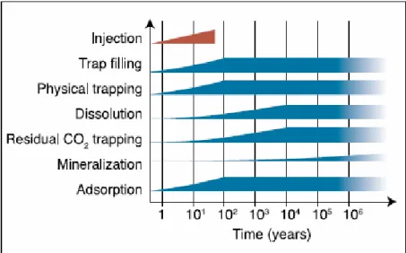
Figure 6: Schematic showing the time evolution of various CO2 storage mechanisms operating in deep saline formations, during and after injection. Assessing storage capacity is complicated by the different time and spatial scales over which these processes occur (source IPCC, 2005).
To understand the difficulties in assessing CO2 storage capacity in deep saline formations, we need to understand the interplay of the various trapping mechanisms during the evolution of a CO2 plume (Section 3.2 and Figure 6). In addition, the storage capacity of deep saline formations can be determined only on a case-by-case basis.
To date, most of the estimates of CO2 storage capacity in deep saline formations focus on physical trapping and/or dissolution. These estimates make the simplifying assumption that no geochemical reactions take place concurrent with CO2 injection, flow and dissolution. Some recent work suggests that it can take several thousand years for geochemical reactions to have a significant impact (Xu et al., 2003). More than 14 global assessments of capacity have been made by using these types of approaches (IEA-GHG, 2004). The range of estimates from these studies is large (200–56,000 GtCO2), reflecting both the different assumptions used to make these estimates and the uncertainty in the parameters. Most of the estimates are in the range of several hundred Gtonnes of CO2. More detailed regional and local capacity assessments are required to resolve this issue.
2.4 Existing and planned CO
2projects
A number of pilot and commercial CO2 storage projects are under way or proposed (Figure 7). To date, most actual or planned commercial projects are associated with major gas production facilities that have gas streams containing CO2 in the range of 10–15% by volume, such as Sleipner in the North Sea, Snøhvit in the Barents Sea, In Salah in Algeria and Gorgon in Australia (Figure 7), as well as the acid gas injection projects in Canada and the United States. At the Sleipner Project, operated by Statoil, about 10 Mt CO2 (at injection rate of 1 Mt CO2 per year) has been injected into a deep subsea saline formation since 1996 (Chapter 8).
The CO2 content in the natural gas varies from 4 to 9.5 % and the CO2 content has to be reduced below 2,5% for export quality. Existing and planned storage projects are also listed in Table 2.
Figure 7: Location of sites where activities relevant to CO2 storage are planned or under way (IPCC, 2005).
At the In Salah Gas Field in Algeria, Sonatrack, BP and Statoil inject CO2 stripped from natural gas into the gas reservoir outside the boundaries of the gas field. Statoil is planning another project in the Barents Sea, where CO2 from the Snøhvit field will be stripped from the gas and in