A Thesis Presented To The Faculty of Alfred University
Ceramic Insulated Droid
The manufacturing of a working prototype
By
Aaron Vit
In Partial Fulfillment of the Requirements for
The Alfred University Honors Program
Under the Supervision of:
Chair: Dr. Seong-Jin Lee Committee Members:
Jim Mighells
Dr. William Carlson
1 Table of Contents:
Abstract………2
Introduction………..2
Apparatus……….7
Procedure………...17
Manufacturing Process………...21
Discussion………..23
Conclusion……….25
Acknowledgement……….28
Bibliography………..29
2 I. Abstract
The Ceramic Insulated Droid project is a design project sponsored by the Alfred University Mechanical Engineering department. This project’s goal is to create a fireproof robot which can enter burning buildings, survey for any potential hazards and find any trapped victims inside before firefighters enter. A drone design was complete, and the process of manufacturing had begun. A frame and the electronics assemblies were completed but the wheel mounting, thermal insulation and several other features were still in the conceptual phase. After taking charge of the project from the previous senior group, several design improvements including the drive shaft design, axle mounting, frame adjustment and electronics assembly placement, were implemented. A finalized prototype was created with operational drive functionality. For further improvement, the next project group will have to cover the drone with ceramic plates before it can be tested in a live fire scenario. The drone was brought from a partially constructed conceptual state to a working, functioning prototype which can be modified for further
improvement.
II. Introduction
Every single year, over 1.2 million fires occur in the United States. Roughly 1/3 of that number are residential fires putting thousands of US families at risk of injury and death every year [7]. This accounts to thousands of deaths each year of victims who cannot escape a fire or firefighters themselves who put their life in harms way to rescue those victims. To reduce the number of deaths in a fire, it would be beneficial for fire departments to have a device which can scout around in a live fire to locate victims and mark potential obstacles for firefighters to watch out for when entering the building. The Ceramic Insulated Droid (CID) is that device, designed to enter a burning building and provide firefighters with beneficial data. This rugged, 6 wheeled vehicle is heavy enough to be able to drive through a closed door and covered in heavy, fireproof ceramic plates, shielding the internal components for up to 25 minutes. Using this drone,
firefighters would reduce the risk of injury or death when entering a burning building and would be able to locate victims faster and save more lives.
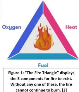
3 For fire to occur, a few key components are needed. Fire is caused by the combination of directed heat on a fuel source surrounded by oxygen
[3]. First, a source of heat is needed to ignite the fire.
In most household fires, this heat source is usually a cooking device, a heating element or electrically caused by faulty wiring. Secondly, a source of fuel is needed to keep the fire fed and aflame. There are many combustible materials which can be sources of fuel to keep a fire burning. The most common fuel sources in homes are paper/wood, oils, gasses, liquids, plastics, and
rubbers. Moisture and fuel composition will determine how combustible it is and how long the fire can use it to sustain the flame [2]. The third and final component is oxygen. Stagnant, ambient air contains roughly 21% oxygen and fire needs only about 16% to ignite. This oxidizes the chemical reaction which causes fire by releasing the heat on the fuel source to generate combustion. These 3 elements are required for a fire to burn. Without any one of these elements, the fire will extinguish. Understanding the key causes of fire helps firefighters fight fires and save lives in live fire scenarios.
The three most common causes of home fires are unattended cooking, heating elements and faulty wiring [1]. Cooking fires are the most common causes of house fires accounting for roughly 50% of them. Most were caused by unattended or uncleaned cooking devices with more being caused by electrical vs gas appliances [1]. Cooking fires have a notable increase during Thanksgiving and Christmas due to an increased number of homes cooking for large amounts of guests. It is recommended that when cooking, be careful and keep an eye on what is being
Figure 1: “The Fire Triangle” displays the 3 components for fire to exist.
Without any one of these, the fire cannot continue to burn. [3]
4 cooked and turn off appliances when not in use. The second largest cause of home fires is
heating elements. During the winters, appliances such as space heaters are often the cause of fire as they are either used too long or are kept too close to flammable items. Furnaces and other heaters can be the cause too if not properly maintained. It is recommended that space heater use should be limited and if used, kept away from flammable objects. The third and final major cause is faulty wiring and electrical based fires. Electrical fires account for roughly 13% of all household structural fires [1]. Most of these fires were caused by faulty house wiring causing an overcurrent in lights or other household appliances. About 25% household electric fires occur while people are in bed accounting for 60% of the fire deaths. Homeowners are recommended to check their house wiring for any signs of faulty operation such as dimming lights, fuses blowing and other indicators. Homes should be equipped with smoke detectors and carbon monoxide detectors to warn occupants inside if a real emergency is to occur. These are the 3 major causes of house fires in the US for the last several decades accounting for over 300,000 fires per year [7].
Firefighting is a very risky occupation especially if entry into a burning building is necessary. Firefighters risk their lives to save trapped occupants and are often rolling the dice for successful rescue. Fire departments have been exploring the use of drone technology for surveillance purposes in live fire scenarios. A drone, or unmanned ariel vehicle (UAV), is a pilotless, remote control flying robot that uses GPS technology for control and flight pattern layout. The military uses sophisticated airplane drones for surveillance and coordinated attack but in the civilian realm, quadcopter drones are widely used. Fire departments have begun employing quadcopter drones for surveillance around a fire to try and control its spread. This is extremely helpful in wildfire scenarios in keeping tabs on how wide the fire spreads and helping
5 firefighters plan where to fight the fire. Many of these drones are equipped with thermal
imaging technology to monitor “hot spots” and help rescue crews locate victims in smokey environments [4]. These drones are extremely useful tools for fighting fires, but they do have limitations. These drones cannot enter an actual fire and still be able to fly. The drone would melt in the fire as it is not properly shielded, and the heat would prevent the quadcopter from being able to fly. Also, if the fire is hot enough, the thermal imaging technology can get confused and might not be able to keep track of firefighters or victims inside a fire. And
especially for small fires, such as a house fire, quadcopters won’t be able to easily locate victims inside. A new kind of drone needed to be designed which can enter a building and see what’s on the inside of the blaze to assist firefighters in rescuing trapped victims. Thus, the Ceramic Insulated Droid project was born.
The Ceramic Insulated Droid is a drone designed to enter a burning building and complete tasks a traditional drone cannot. This drone is not a traditional flying drone, rather a rugged, tank like, remote control vehicle which can reach areas that humans cannot. This vehicle is designed to be covered in, fireproof, ceramic plates giving it the ability to enter a fire without damaging the internal electronics. The battery capacity is similar to that of a flying drone, roughly 25 minutes, giving it enough time to enter a building, scout around and locate victims and obstacles to assist firefighters to save lives. This kind of vehicle is extremely applicable in residential fires where flying drones cannot see inside. The rugged design using treads gives the drone the ability to cross many types of terrain and unstable ground such as being able to drive up the stairs inside a house. A drone such as this will give firefighters another tool to help save lives and rescue trapped victims inside a live fire.
6 This project became an interest to me for multiple reasons. Coming to Alfred University as a freshman, I was encouraged and joined the Alfred University Drone Club. It was the first time I had been introduced to drone technology and even learned how to fly and repair small UAV drones. This club aspired to grow and become a business entity doing small photography projects for the school and even possible agricultural projects with an industrial capable drone.
Upon returning to college after my co-op as a junior, I wanted to do a senior project which dealt with drone technology. I had done some previous exploratory work on the SAE Baja and Design Build Fly projects as an underclassman but found conflicting leadership and difficulty in giving input on design decisions. I wanted a smaller project which I could have more input and more influence in the final design and use my unique skillset to make a working project. About halfway through my junior year, I was introduced to the Ceramic Insulated Droid. A small team of about four seniors was working on the project at the time and they were looking for someone to pass the project on to. I spent the second semester of my junior year taking in everything I could learning from the last senior group and getting up to date on the progress. From there, throughout my Senior semesters, I was able to lead the team and take the partially finished drone and make it operational.
The progress on the project by the time I joined in and took over the responsibility of leading, was in between designing and construction. The initial frame had been constructed and welded and many parts were already purchased. In many areas in the design, there wasn’t a clear solution on how the parts would fit together. For example, there was no drive shaft design for the driving gears and there were many questions on how the axles would be mounted to the frame. As the previous group of seniors passed responsibility, I was tasked with taking a partially constructed drone and making it operational. In trying to preserve what has been
7 worked on, I made several design improvements and solutional fixes taking a frame and
electronics assembly and putting the pieces together. With these adjustments, the drone would keep to its original design and became a working prototype of a fireproof, ground-based drone.
III. Apparatus Original Design:
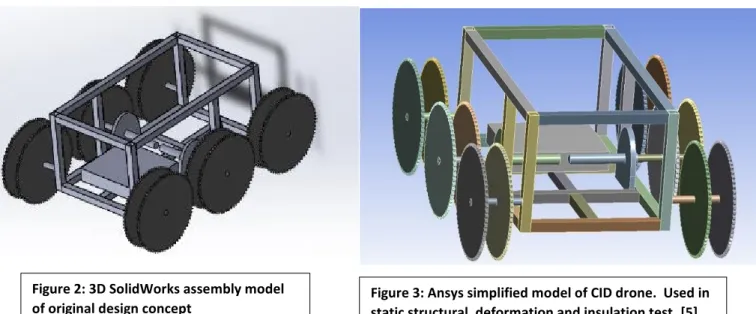
The design of this drone is the combination of basic components for a UAV quadcopter and a treaded tank. A rigid steel, skeletal frame creates a strong support structure to build from.
The Rectangular frame is designed large enough to hold the large, tough box mini motors which drive the vehicle, the battery, and internal electronics. 12 heavy, steel sprockets act as driving wheels. They are all interconnected by a bike chain acting as a tread, giving this vehicle the ability to cross all terrains. Two sets of three sprockets flank either side of the drone, giving each side two complete tread sets. This allows the vehicles to grip the terrain it crosses better and distribute the power from the driving motors more efficiently. The drive gear is in the center of each side with independently operating motors on each. The electronics, servos, antenna, and
Figure 2: 3D SolidWorks assembly model
of original design concept Figure 3: Ansys simplified model of CID drone. Used in static structural, deformation and insulation test. [5]
8 power connectors are all housed within the main frame. A large car battery is mounted in the rear, providing at least 30 minutes worth of charge. The entire frame is covered with ceramic insulation tiles which protect the inner electronics from the fire. All exterior facing parts, Wheels, shafts, and collars are made of steel to resist the hot temperature of the fire. This concept design provided a basis for to move forward from, combining ariel quadcopter with rugged tank to create a fireproof off-road vehicle capable of helping firefighters save lives.
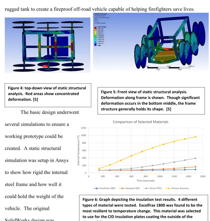
The basic design underwent several simulations to ensure a working prototype could be created. A static structural simulation was setup in Ansys to show how rigid the internal steel frame and how well it could hold the weight of the vehicle. The original SolidWorks design was
Figure 4: top-down view of static structural analysis. Red areas show concentrated deformation. [5]
Figure 5: Front view of static structural analysis.
Deformation along frame is shown. Though significant deformation occurs in the bottom middle, the frame structure generally holds its shape. [5]
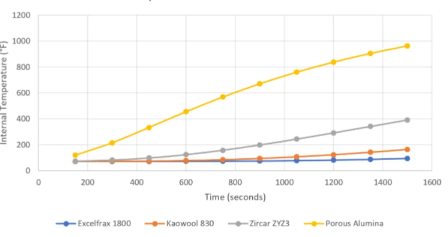
Figure 6: Graph depicting the insulation test results. 4 different types of material were tested. Excelfrax 1800 was found to be the most resilient to temperature change. This material was selected to use for the CID insulation plates coating the outside of the drone. [6]
9 simplified and imported into Ansys for analysis. A large square block was placed at the rear of the vehicle to represent the battery and electronics weight and force was added to represent the weight of the driving motors. The resulting analysis showed the weight distributed throughout the frame but a significant concentration in the back [5]. The resulting deformation shows extreme circumstance, but the main frame generally held its shape. Finally, an insulation test was conducted. Using a simple insulation frame design of 4 different types of ceramic insulation, it was found that Excelfrax 1800 held the interior temperature the lowest and kept internal temperature constant, even at an exterior temperature of 1300 degrees [6]. This material was optimal for plating the drone as it can withstand the blazing hot temperatures of a fire.
These experiments provided beneficial data for deciding to move forward with this design. The tests proved the design could withstand the heat of the fire and the weight of the individual components. Manufacturing would begin on this design to create a working prototype.
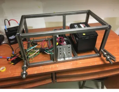
Manufacturing had begun on the drone by the time I had joined the project group. The steel frame was cut and welded, and initial mounting holes were drilled on the outer half of the steel tubing at the 4 corners where sprockets would be mounted. The
motors, battery, sprockets, chain, and internal electronics components were already purchased and ready for assembly. The internal electronics, 4 motor servos, main board,
Figure 7: The CID manufacturing progress at the middle of the Spring 2020 semester. Parts were purchased and ready for assembly and project had a direction for completion. [5]
10 battery voltage converter and antenna were mostly connected, and components were tested for operation. For batteries, there were two available choices: A large or small, 12-volt lead acid battery. The smaller battery was significantly lighter and took up less space inside the frame than the large battery. Several small, shafts were cut to mount the sprockets and two of them were cut with a thread on the inside to mount to the motors. It was not in any way a complete design, but it had the potential for a complete and working prototype.
After the previous senior group left and I took charge of the project in 2020, I noticed several design/manufacturing flaws I hoped to fix. First and foremost was related to some of the parts that were purchased. The sprockets had an internal mounting diameter that was not
standard. Most standard shaft sizes are along quartile or eight measurements (i.e., 1/8, ¼, ½, 5/8,
¾, 1-inch diameters). The sprocket mounting diameter was .71875 inches, or 23/32 inch. This made it nearly impossible to find mounting shafts and collars that will hold the sprockets into place without adding unnecessary extra cost. Some of the small, non-motor shafts were cut to this dimension, but there are no, standard sliding collars or bearings that are designed to this dimension. Also, none of the sprockets had any features to prevent slippage. No key cuts or rings were created for mounting a collar to, making it impossible to design a drive shaft for them.
An idea was floated around to weld 608 bearings to the shafts, but welding bearings would prevent them from function and ruin both parts. A new design would have to be added to improve these parts so they could be properly mounted to both standard and drive shafts without slipping.
The second major problem was driving shaft and axle mounting. For the non-driving shafts, only a single hole was cut. It would be impossible, even with a weld for support, for the small cut shafts to support the weight of the vehicle and the weight of the sprocket mounted to it
11 without slipping or falling out entirely. For the drive shafts, no solution had been thought of for mounting the driving gears. A threaded rod was the only thing holding the gear shafts to the motors. This would hold but would not prevent slippage, especially if the drive gear moves the same direction the screw shaft is attached as this would cause the threaded rod to unscrew entirely and fall off the motor shaft. A new method for attaching the shafts would be needed to make sure they do not slip during operation or fall off entirely.
The third and final issue was the electronics assembly. Though many of the wires had been hooked up, there was no solution for how to configure or mount them to the inside of the frame. With electronics, it is imperative that they are mounted properly so that wires aren’t overstretched or bent over their limit to prevent connections from falling apart. An idea was thought of using epoxy to attach them to the side of the frame, but there was no guarantee that it would hold. There was the possibility that the epoxy could ruin the boards, or the wires
connected to them. A mounting method was needed both to keep electronics in place, mount them to the frame and prevent destruction to the components during the mounting process.
Joining this project in the beginning of the spring 2020 semester, I was able to learn everything about the project’s progress and current design dilemmas. Unfortunately, due to the Covid-19 Pandemic, progress was halted shortly into the semester as school transitioned to a fully virtual setting. Over the summer, several ideas were formulated to fix the current problems of the design in its partially manufactured state. Returning to in-person learning in Fall 2020, I was able to implement some of my design change ideas, leading a small group in the direction of completing a working prototype.
12 Design Improvements/Rework:
Sprocket diameter change/mounting key and motor mount designs:
The First design issue to be improved was to adjust the sprocket mounting diameter to a more standardized size. The sprockets were originally purchased with a .71875 or 23/32 inch diameter for mounting onto a shaft. This is a nonstandard size, making it difficult to cut
mounting holes and to purchase and adjust mounting shafts without unnecessary extra spending.
The easiest fix to this was to enlarge the diameter to .75 or ¾ inch diameter, a more standardized size. This would allow ease of repair and replacement of parts if anything is damaged during a simulation or live fire scenario.
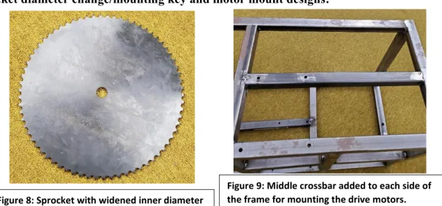
Another adjustment made was the addition of a crossbar on each side of the drone frame.
The tough box mini motors have mounting points at the base and top of the mounting plate. To mount it on the frame properly, mounting holes would need to be placed at the bottom of the frame and in the middle where the top mounting points are. To achieve this, another piece of thin, frame metal can be added giving a point for the motors to mount to. With this addition, the motors can be mounted properly to the frame and the shafts pointed in the proper orientation for the drive gears to function.
Figure 9: Middle crossbar added to each side of the frame for mounting the drive motors.
Figure 8: Sprocket with widened inner diameter
13 Non-motor shaft mounting design:
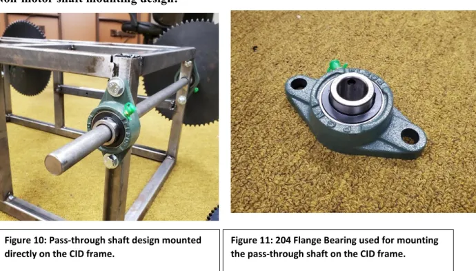
The second major design improvement was on the non-motor shaft design. The current design did not account for the weight of the vehicle or the weight of the sprockets. Even with a weld to hold the small shafts in place, the likelihood of slippage or the shaft/frame breaking at that point was extremely high. The best solution to add strength and align the opposing shafts properly was to make two axles connecting the opposing ends. With the sprockets now standardized at a ¾ inch diameter, a ¾ inch diameter shaft was used to pass through the frame and connect the opposing sides. To complete this task, the second half of the mounting hole on the inside of each frame corner had mounting holes already cut. First, the precut hole would have to be widened, then the second hole would be cut based on the first hole’s position. With these holes cut, a path was created to fit the axle inside.
A secondary aspect of this design required axle did not move linearly from side to side.
The axle was designed large enough to allow clearance to mount the sprockets but not much extra room. Linear slippage needed to be prevented to keep the sprockets on the shaft and to
Figure 10: Pass-through shaft design mounted directly on the CID frame.
Figure 11: 204 Flange Bearing used for mounting the pass-through shaft on the CID frame.
14 keep the linear position fixed. To achieve this, a specialty type of bearing, called a flange
bearing would be assembled around the shaft hole to hold the shaft in place. The flange bearing mounts vertically to the frame and the shaft passes through the bearing. A set screw is tightened on the bearing to prevent the shaft from slipping and fixing its position in relation to the frame and sprockets. The only feature needed to be added to the frame was mounting holes for the two screws at the top and bottom of the flange bearing. This design created a sturdier axle for the non-motor shafts allowing for easy assembly, mounting and the ability to replace a shaft or sprocket if it becomes worn out as disassembly is simple.
Driving shaft design:
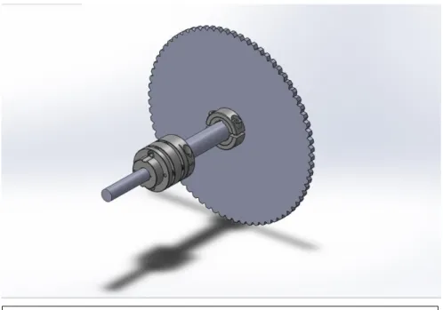
The third major design change was the design of the driving gear and drive shaft. There was no solution for mounting the driving gear to the drive motor. The Andy Mark tough box mini, the motor assembly used on the drone, has a threaded screw hole and a single keyhole on the end of mounting rod with no other features for mounting. The mounting rod on the minibox has a ½ inch diameter and the driving sprockets have an inner diameter of ¾ inch. The sprockets
Figure 12: Drive Shaft Design using servomotor coupler and keyed collars.
15 also did not have any keyed features to prevent them from slipping on a shaft. To fix this issue a few specialized parts were needed.
First, a servomotor precision coupler was needed to clamp down on the minibox shaft and the sprocket shaft. This part is designed specifically for shaft couplings on moving parts to reduce vibration and provide a firm grip on the shafts it is attached to. At one end, the clamp diameter measures ½ inch and at the other, ¾ inch, making it the perfect component for this application. This part would work in conjunction with the threaded rod on the inside of the mounting shaft. It provides a clamp on the outside of the shaft while the threaded rod provides a connection from inside. This provides an extremely rigid mount preventing axle slippage or any disconnect between the driving sprocket and the driving gears.
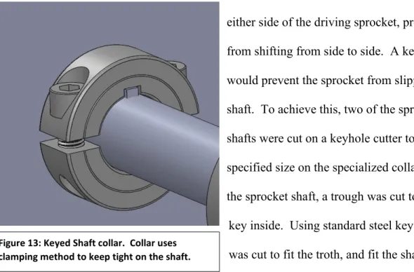
The other specialized part was two shaft collars with keyhole cuts. These were placed on either side of the driving sprocket, preventing it from shifting from side to side. A key cut design would prevent the sprocket from slipping on the shaft. To achieve this, two of the sprocket’s shafts were cut on a keyhole cutter to the
specified size on the specialized collars. Then on the sprocket shaft, a trough was cut to place the
key inside. Using standard steel key stock, a key was cut to fit the troth, and fit the shafts and sprocket. The shaft collars clamped down on the sprocket shaft keeping the key in place.
This driving shaft design successfully mounted the driving sprocket to the tough box mini driving shafts on both sides of the drone. This design prevented the sprocket from slipping on
Figure 13: Keyed Shaft collar. Collar uses clamping method to keep tight on the shaft.
16 the drive shaft and keeps movement tight to the drive shaft. The key advantage with this design is that it is completely removable. The shaft collars can be unscrewed, and the servomotor coupler can be released and unscrewed giving the user access to the motors for repair. It also leaves the possibility open for removable insulation plates. The only adjusted feature on the plate would be a small hole for the protruding shaft from the motors. This would keep the inside protected and insulated from flames in a live fire scenario.
Electronics mounting:
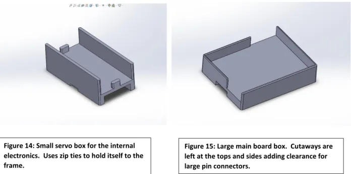
Upon joining this project group, there was no solution for attaching the internal electronics to the frame. The electronics were mostly wired up with roughly 4-5 servos, an antenna, a main board, and a voltage converter, totaling to 8-9 components. These needed to be placed based on how much cable existed between neighboring components and their overall relationship with the main board. To solve this, several different types of 3d printed boxes were designed. These boxes were designed around each component dimensions specifically leaving clearance where entering and exiting wire leads protrude. These boxes were also designed using zip ties to mount them to the frame and the electronics themselves can sit loosely inside being
Figure 14: Small servo box for the internal electronics. Uses zip ties to hold itself to the frame.
Figure 15: Large main board box. Cutaways are left at the tops and sides adding clearance for large pin connectors.
17 held in by friction. The advantage using this approach is the design is easy to change and adjust based on the orientation on the frame and because it is inside and insulated, these parts do not necessarily need to be fireproof. With new additions in materials to 3d printing, it would be ideal to print these out of a carbon fiber hybrid material which has significant thermal reduction properties which give the material more resistance to heat over normal thermoplastic. These boxes provided an excellent mounting solution which is improved by its ability to be adjusted.
These designs can be reused in future versions of this prototype by future senior groups if desired.
IV. Procedure
The procedure for applying these design changes occurred as follows. Each design improvement feature has its own separate procedure displayed below:
Sprocket diameter change:
1. Obtained cutting materials: .75 inch diameter cobalt drill bit, cutting oil, and 6 of the sprockets.
2. Set up the cut on the mill: aligned one sprocket with the center of the mill chuck using a center gauge. Vise grips were used to clamp the sprockets to the table, preventing them from moving or spinning during the cut.
3. Performed the cut: Applied oil to drill bit to prevent overheating and allowing smooth performance creating a clean and accurate cut.
4. Repeat steps 1-3 for the remaining 5 sprockets.
18 Addition of the middle mounting bracket to frame:
1. Obtained thin square steel bracket for middle mounting bracket addition.
2. Obtained length measurement for the mounting bracket: Using the tough box mini motor mounting bracket for height, the length was measured from the central vertical bracket to the front/back edge of the frame at the mounting height.
3. Cut the material to length: Using the metal bandsaw, square steel brackets were cut to the appropriate lengths.
4. Mounted the bracket to the frame: At the end points, welding operations were performed to fuse the bracket to the frame. After welding was completed, grind down extra beads to make the bracket flush with the frame.
5. Drilled mounting holes: A hand drill and titanium coated bits were used to drill mounting holes for the motor bracket at the appropriate sections on the newly added middle bracket and bottom of the frame.
6. Mounted driving motors: The Motors were attached at the hole locations along the mount bracket and the appropriate hardware.
Non motor shaft mounting creation:
1. Obtained materials: Purchase two .75 inch diameter steel rods, four 204 flange bearings and the associated mounting hardware for the flange bearings to mount the axles to the drone.
2. Cut the shafts: Measured axles to the appropriate length. They should stretch through the drone frame and have enough room at either end for two sets of sprockets. Cut the shafts at the measured length using the metal band saw.
19 3. Created shaft holes in the frame: using the pre-drilled mounting points, holes were
drilled through the second half of the steel frame at each corner creating 4 through holes to mount the shafts through.
4. Created mounting holes for flange bearings: using one of the bearings, drill points were marked on the frame for mounting holes. Mounting holes for the flange bearing were drilled using a hand drill and titanium bits.
5. Mounted shafts and bearings to the frame: placed shaft through the shaft holes and attach flange bearings. Screwed in appropriate hardware to mount the bearings to the frame.
6. Added Sprockets: Attached sprockets to the shaft. Linear collars were used to keep the sprockets straight and in position.
Drive shaft design:
1. Obtained materials: two servomotor couplers for axle mounting, keyed linear collars for sprocket mounting and key stock.
2. Performed key trough cut on sprocket shafts: On the pre-cut sprocket shafts, a trough was cut at the outer end of the shaft for the drive sprockets using the mill. The trough
measured roughly .1875 inches wide to accommodate the key stock. Vice grips held the shafts in place. An end mill bit was used to perform the cuts.
3. Cut key holes in the drive sprockets: Using a key cutter, keyholes were cut in two of the sprockets at the .1875 inch wide measurement. Depth for the cut was standardized base on the key width.
4. Assembled the drive shaft: Attached the servomotor couplers to the motor shafts.
Screwed in the central threaded rods. Attached the sprocket driving shafts to the threaded rod and tightened the second end of the servomotor coupler.
20 5. Attached the driving sprockets: Placed key stock, cut to the appropriate trough length,
inside the trough. Slid one of the linear collars and tighten it into place. Added each keyed sprocket to the key trough and lock into place with the second linear keyed collar.
Electronics mounting:
1. Obtained measurements: Measured each component of the electronics assembly: four servos, main board, voltage converter, antenna assembly, and power supply converter.
Obtained length, width, and height measurements as well as any specialized mounting features with each component.
2. Designed mounting boxes in SolidWorks: Using gathered dimensions to create mounting boxes. The top of each box fits the outer dimensions of each component and the bottom measured the width of the thin steel used on the frame. Holes were cut in the bottom sides for zip tie assembly.
3. Printed the boxes: Sliced the models appropriately making sure there weren’t any unnecessary overhangs to increase print quality. Using a Prusa i3 mk2.5 MMU2S printer, print the boxes using PLA plastic.
4. Assembled the electronics and mount them to the frame: Attached all electronics components according to the Andy Mark electronics guide for robot servo control.
Mounted each component to its associate 3d printed box. Attached the boxes to the frame using zip ties.
21 V. Manufacturing Process
Figure 16: Droid frame assembly complete. Figure 17: Addition of middle bar for mounting the motors. Includes mounting holes.
Figure 18: Frame with 4 sprockets mounted.
Figure 19: Sprocket driving shaft with key cut and threaded rod.
Figure 20: Driving shaft assembly.
Figure 21: Electronics mounting boxes being created on a Prusa i3 3D printer.
22 Figure 22: Servo mounted in 3D printed box.
Figure 23: Andy Mark tough box mini motors mounted to the frame with drive shaft installed.
Figure 24: Fully assembled drone with drive shaft.
Figure 25: Drive shaft sprocket front. Figure 26: Full assembled drone with wired electronics
23 VI. Discussion
Overall, the manufacturing process for the droid went smoothly. The sprocket diameter adjustment, though difficult to set up the cut, was consistent through every cut sprocket. The cobalt bit cut through the hardened steel sprocket without any issue and the adjustment changed the inner diameter from a nonstandard 23/32 inch measurement to a ¾ inch inner diameter for easy mounting to the axle shafts. The middle frame bracket was cut too short at first for one side, but thankfully, extra material was available and a new part with the correct dimension was created. The welds for attaching the middle bracket were okay, but not exact. The weld beads were cleaned using a grinder making the inner and outer surfaces of the bracket flush with the frame. The motor mount holes still fit on the middle brackets, but not exactly along the
centerline. The mounting holes were drilled after the middle brackets were added to account for small inaccuracies in the welding process. The motors, though a tight connection, still fit on the frame after the holes were drilled and the motors were properly aligned on the frame.
The non-motor axle designs worked relatively well but could use some improvement in future revisions. The shaft holes were based off precut holes on the frame from previous project groups. Unfortunately, they were not cut at the same height and when drilled through, were a bit skewed when placing the axle through. This could have been caused by slight skews in the welding process when the frame was originally put together or small miscalculations in
measurements. Fortunately, these holes could be widened, giving more clearance for the shaft to pass through at the correct orientation. Another issue with the axle design were the flange bearings. Due to poor manufacturing of these parts, many of the bearings were not properly seated inside the flange. This meant that the axle passing through would be skewed and not at an exact, 90-degree angle. To mount the axles on the droid, the 4 best flange bearings were chosen
24 and used for mounting. Despite these being mostly straight, they were not exact, and both axles were skewed slightly, and motion was prevented. For the vehicle's ability to move, this was a low impact issue because all the sprockets are linked by a tread so a slight skew should not prevent movement. Also, the sprockets are designed to slide freely on the shaft and aren't attached directly; so, the locked shaft did not impact droid movement. Overall, this design works and improves the durability of the axle shafts. Due to cheap components and
manufacturing mistakes, the axle shafts are slightly skewed. This can be improved in the future by using better quality components and adjusting the axle through holes.
The driving shaft design proved to be a successful method for moving the drone. The servo motor coupler provided an excellent link between the smaller diameter motor shaft and the larger diameter sprocket driving shaft. With a threaded rod on the inside of the sprocket shaft, the servo motor coupler provided a secondary lock on the outside preventing the shaft from slipping. The keyed sprocket design successfully locked the driving sprocket in place and prevented slippage. The driving sprocket locked in place linearly by two keyed collars and rotationally by the key, keeping it firm to the shaft and locked into the movement of the driving motors. There was however, one small part of the manufacturing that requires
improvement. The original driving sprocket shafts were cut at the incorrect, 23/32-inch
diameter. The servo motor coupler is a tightly toleranced part and was unable to grip the shaft at the smaller diameter parts. As a temporary solution, electrical tape was added around the shaft to fill in the spots where it could not be gripped preventing slippage. A future solution to fix this issue would be to recreate the sprocket driving shafts with ¾ inch diameter steel rods giving the servo motor coupler more material to grip.
25 The electronics mounting boxes provided an excellent mounting solution for the servos, main board, antenna, and voltage converter components. Each of these parts were custom designed and printed to fit each component and they provided a strong, and functional fit. Zip ties, though not the strongest connection features, provided an adequate mounting solution to attach each box to the frame. One small issue with the current electronics assembly was the ability to utilize these boxes and mounting features with the current setup. The cables connecting each
component currently are too short to realistically mount any of the electronics components to the frame in any spot. For future improvement, more cable should be added to properly manage the electronics assembly and arrange it inside the frame to utilize the space and spread-out
components, so they are not in a large, disorganized bundle. Though this method was not a perfect solution, it proved a concept that could work, with small adjustment, in practice.
VII. Conclusion
The Ceramic Insulated Droid provided a proof-of-concept transformation from a 3D design to an operating prototype. Though the manufacturing process wasn't an exact replication of the design, it improved upon its problems creating a much more stable, durable, usable prototype. This drone was able to drive upon command from the remote, moving this extremely heavy vehicle at a decent speed across a room. With the addition of the treads and adjustment in cable management for the interior electronics, this drone should have the capability to complete the tasks it was designed for.
To complete this drone for testing in a live fire scenario, a few more items will need to be completed. The most significant of these will be the addition of the ceramic plates. These plates need to be attached in two parts: one plate permanently attached along the bottom of
26 the drone and a large “hood” design to cover the rest of the frame. This “hood” will have holes for protruding shafts and must be removable to provide access to the electronics for battery recharging and repair. The other addition to this drone will be the camera. This is crucial for guiding the drone through a burning building where the user won’t have direct visibility of the vehicle. This part will either be added at the front or the top of the vehicle, facing forward to help guide the vehicle. With the addition of these two components, the drone can be tested in a live fire scenario and the vehicle's application can truly be tested.
In considering a revised design of the current drone, a couple improvements should be implemented. First, a revised frame with the front sticking out in front of the sprockets should be added. For this drone to be able to knock down a large house door, a “ramming”
feature should be added to the front for ease of operation while completing this
action. Secondly, an improved battery should be researched. The current battery should power the droid for roughly 25 minutes. Giving the drone even more run time could allow for this drone to aid firefighters even while they are inside the building looking for
victims. Finally, the frame should be redesigned from the perspective of improving thermal insulation. In doing so, the drone will be able to last longer inside a live fire, giving it more time to provide useful feedback to firefighters on the outside before the internal components overheat.
The Ceramic Insulated Droid will become a necessity for fighting fires in the near
future. This device will provide fire departments with useful data to save more victims inside fires, prevent injuries of entering firefighters, and provide data for reducing fires in the future. The current device provides a working prototype that can be tested in a live fire
27 scenario. With some small tweaks and design improvements, this drone will be an
indispensable tool for firefighters to save lives.
28 VIII. Acknowledgement
A. Vit would like to thank Adel Alyahya, James Eddlestone, Weston Kogachi, Professor Seong-Jin Lee, Thomas Minnick, and Natalie Turco for their previous work on this project. The droid would not be in an operational state without their past efforts in designing and initial manufacturing of the prototype.
29 IX. Bibliography
1. Ahrens, M., “Home cooking fires,” NFPA Available: https://www.nfpa.org/News-and- Research/Data-research-and-tools/US-Fire-Problem/Home-Cooking-Fires.
2. “Back to Basics with the Fire Triangle,” Elite Fire Available:
https://www.elitefire.co.uk/help-advice/basics-fire-triangle/.
3. Carruthers, T., “Why fires burn,” Australian Academy of Science Available:
https://www.science.org.au/curious/earth-environment/why-fires-
burn#:~:text=Fire%20is%20the%20result%20of,oxygen%20in%20the%20surrounding%
20atmosphere.
4. “Firefighter Drones – How Drones are Being Used for Helping Fire Departments,” Drone Nodes Available: https://dronenodes.com/firefighter-drones/.
5. Minnick, T., Alyahya, A., “Development of Ceramic Insulated Droid for High Temperature Applications,” Alfred University, 3-8
6. Turco, N., Eddlestone, J., “Thermal Analysis of Ceramic Insulation for Implementation in Remotely Operated Fireproof Robot,” Alfred University, 4-7
7. “U.S. fire statistics,” U.S. Fire Administration Available:
https://www.usfa.fema.gov/data/statistics/#tab-2.