While the book Turbomchinery Flow Physics discussed in great detail the aerodynamics, heat transfer and performance aspects of almost all thermal turbomachines, the current book deals with the air thermodynamic design of gas turbine components and their integration into a complete gas turbine system . The failed tests showed that the prerequisite for a successful gas turbine design is the full understanding of the underlying viscous flow physics and its mathematical description.
Greek Symbols
T stress tensor, T = eiej-ij For stagnation or total temperature Tc static temperature of blade cold side Th static temperature of blade hot side TW blade material temperature.
Subscripts, superscripts
- Power Generation Gas Turbines
- Compressed Air Energy Storage Gas Turbines, CAES
- Power Generation Gas Turbine Process
- Significant Efficiency Improvement of Gas Turbines
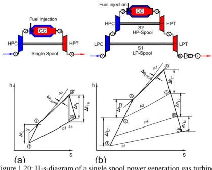
A schematic illustration of the aforementioned reheat concept is given in Figure 1.11 in terms of T-S-diagrams for a basic gas turbine (a) and a gas turbine with a reheat stage (b). Using a 36% efficiency gas turbine as the base GT, a reheat stage was added as shown in Figure 1.11.

HPCFan
- Aircraft Gas Turbines
- Aircraft-Derivative Gas Turbines
- Gas Turbines Turbocharging Diesel Engines
- Gas Turbine Components, Functions
- Group 1: Inlet, Exhaust, Pipe
- Group 3: Compressor, Turbine Components
Another advanced aircraft engine is the Rolls Royce Trent 1000, a three-coil engine shown in Figure 1.21. As Figure 1.31 shows, low-temperature air enters the recuperator tubes, which are exposed to the hot gas.
Gas Turbine Cycles, Processes
- Gas Turbine Process
Inside the combustion chamber, the fuel mass flow is thoroughly mixed with the compressor air. We introduce the following definitions for the recuperator air and gas side (RA, RG) as well as the combustion chamber (CC) pressure drop coefficients:. 7) The thermal efficiency is defined as.

Improvement of Gas Turbine Thermal Efficiency
- Minor Improvement of Gas Turbine Thermal Efficiency
- Major Improvement of Gas Turbine Thermal Efficiency
- Compressed Air Energy Storage Gas Turbine
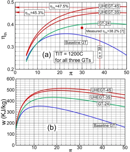
The T-diagram of the GT24/26 gas turbine compared to a conventional baseline model is shown in Fig. This represents an increase of at least 5% over the efficiency of the most advanced gas turbine engine which is close to 40%.
Mass Flow Balance
Design of a modern gas turbine engine with its components requires thorough knowledge of aero-thermodynamic, heat transfer, combustion and solid mechanics design of these components. Aerothermodynamics is the very basic tool for design, exterior design and dynamic calculations of gas turbine components and thus the gas turbine system. The subject of aerothermodynamics and its application to engineering is comprehensively treated by Schobeiri, [1], [2] and [3].
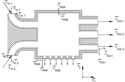
In the following sections, we summarize the aerodynamic conservation laws that are essential for application to the gas turbine components. We start with the mass flow balance, which will be followed by the linear momentum, angular momentum and the energy balance. To apply the mass flow balance to a turbine or cascade vane duct, the control volume should be placed in such a way that it includes quantities that we consider known as well as those that we seek to find.
The last surface integral is responsible for the mass flow injection through the film cooling holes.
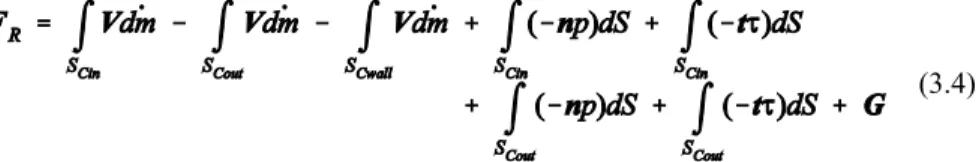
Balance of Linear Momentum
Because of the periodicity of the flow through the cascade, the surface integrals along these flows will cancel each other out. If there is no mass diffusion through the wall surfaces, the last integral in Eq. An order-of-magnitude estimate shows that the inlet and outlet shear stress terms are generally very small compared to the other terms.
It should be noted that the wall shear stress is already included in the resultant force FR.
Balance of Moment of Momentum
The peripheral speed difference is responsible for the compressor's total pressure increase and thus the power consumption. Although the application of conservation laws is discussed at length in the following chapters, it has been found necessary to present a simple example of how momentum is obtained by using the velocity diagram of a single-stage axial compressor. The constant radii at the entrance and exit of the center section result in a simplification of Eq.
It states that the energy consumption of the compressor is related to the flow deviation expressed by the difference in peripheral speed. However, for each type of compressor design (axial, radial, subsonic, supersonic) there is always a limit to this difference dictated by flow separation, as we will see later. For the case where no vanes are installed in the duct and the axial velocity distributions at the entrance and exit of the duct are completely uniform, one
Assuming an impure flow through the exit diffuser of a gas turbine, the existence of a vortex helps the boundary layer to remain attached.

Balance of Energy
- Energy Balance Special Case 1: Steady Flow
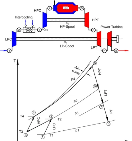
A modern power generation gas turbine with a single shaft, two combustion chambers, a multi-stage compressor, a single-stage reheat turbine and a multi-stage turbine. Assuming an impure flow through the exit diffuser of a gas turbine, the existence of a vortex helps the boundary layer to remain attached. 3.15). Equation (3.14) shows the general form of the energy equation for an open system with a fixed control volume.
For technical applications, several special cases are used, which we will discuss in the following. Equation (3.15) is the energy balance for a turbomachine with thermal energy (heat) addition or rejection (kJ/s) per unit if time and shaft power are supplied or consumed Energy balance Special case 2: Constant flow, constant mass flow. applications the mass flow remains constant from the inlet to the exit of the machine In many applications the mass flow remains constant from the inlet to the exit of the machine. Examples are uncooled turbines and compressors, where no mass flow is supplied during the compression or expansion process.
Using the above equation, the energy balance for the main components of a gas turbine engine is shown in Fig.
Application of Energy Balance to Gas Turbines Components
- Application: Combustion Chamber, Heat Exchanger
As discussed in section 3.6.1, the total pressure difference is directly related to the entropy increase caused by the viscosity of the fluid. As a result, the total enthalpy at the output is the sum of the total enthalpy at the inlet plus the heat added to the system. The thermal energy flow takes on positive (heat addition) or negative signs (heat rejection) based on the direction of the heat flow relating to the individual volume elements.
Part of the cooling air enters the inside of the wing and passes through several channels, Fig. Inside these channels, an intensive heat transfer from the wing material to the cooling medium takes place, which results in a significant reduction of the wing's surface temperature. Considering the negative signs of the specific mechanical energy lm and the heat q, we obtain from Eq.
From this diagram we can see that the mechanical energy of the specific stage of the turbine is reduced by the amount of heat rejected by the blades.
Irreversibility and Total Pressure Losses
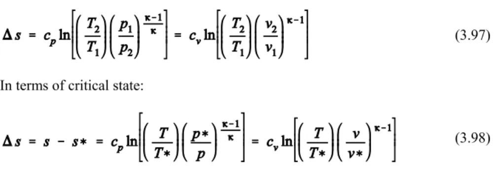
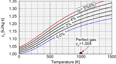
For the working media used in thermal turbomachines, such as steam, air and combustion gases, the thermodynamic properties can be taken from the appropriate gas and steam tables. In general, the specific heats at constant pressure cp and constant specific volume cv are functions of temperature. With this relation, the entropy change can be obtained by Eq. 3.35) in terms of enthalpy or internal energy,.
Assuming lower temperatures where cp and cv can be approximated as constants, the entropy change is calculated by integrating Eq. Equations (3.40) and (3.41) are valid under the assumption of perfect gas, cp and cvg f(T), for estimating entropy changes. Considering the air of the working medium or the combustion gas as a calorically perfect gas leads to substantial errors.
If the total pressure loss coefficient is known, the entropy change can be calculated using Eq.
Flow at High Subsonic and Transonic Mach Numbers
- Density Changes with Mach Number, Critical State
- Effect of Cross-Section Change on Mach Number
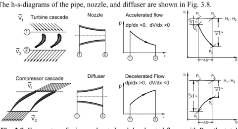
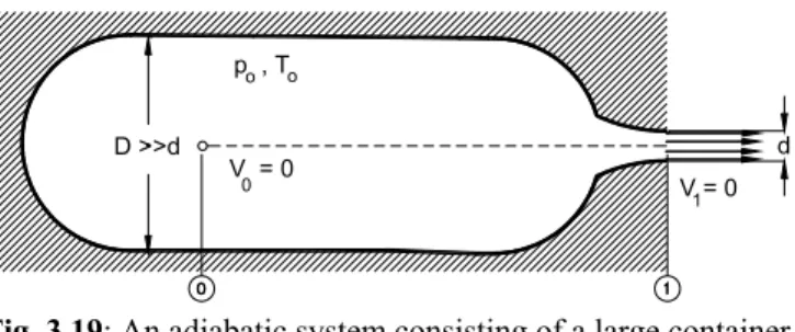
At this pressure ratio, the mass flow rate per unit area has a maximum and the flow rate at the outlet nozzle is equal to the speed of sound. We assume that in the container, due to , the velocity is negligibly small compared to the velocity at the nozzle exit. The influence of the Mach number gives rise to further differences between compressible and incompressible flow.
In this case, the flow accelerates in the convergent part, reaches Mach number M = 1 in the throat and is additionally accelerated in the divergent part of the nozzle. In this case, the Mach number continuously increases from subsonic at the inlet to supersonic at the exit. The nozzle section behind the damper then acts as a subsonic diffuser, theoretically raising the pressure behind the damper to ambient pressure.
Next, a post-expansion takes place in the free jet, and the pressure at the nozzle exit expands to the ambient pressure again through stationary expansion waves (Fig. 3.30).
We combine the differential form of the momentum equation,
3.89) To find the flow quantities for the Rayleigh process, we present the calculation of a pressure ratio.
We combine the differential form of the continuity equation (3.84) with the differential form of the equation of state for ideal gases. With this step we eliminate
Inserting the velocity ratio (3.88) into momentum equation (3.86) and the equation of motion (3.84), we obtain for the pressure ratio,
- The Normal Shock Wave Relations
- The Oblique Shock Wave Relations
- Detached Shock Wave
- Prandtl-Meyer Expansion
- Energy Transfer in Turbomachinery Stages
- Energy Transfer in Relative Systems
- General Treatment of Turbine and Compressor Stages
- Dimensionless Stage Parameters
- Relation Between Degree of Reaction and Blade Height for a Normal Stage Using Simple Radial Equilibrium
- Effect of Degree of Reaction on the Stage Configuration
- Effect of Stage Load Coefficient on Stage Power
- Unified Description of a Turbomachinery Stage
- Generalized Dimensionless Stage Parameters
- Special Cases
- Case 1, Constant Mean Diameter
- Case 2, Constant Mean Diameter and Meridional Velocity Ratio In this special case, circumferential and meridional velocities are equal leading to
- Increase of Stage Load Coefficient, Discussion
- Blade Force in an Inviscid Flow Field
- Blade Forces in a Viscous Flow Field
- The Effect of Solidity on Blade Profile Losses
- Relationship Between Profile Loss Coefficient and Drag
- Optimum Solidity
- Optimum Solidity, by Pfeil
- Generalized Lift-Solidity Coefficient
- Lift-Solidity Coefficient for Turbine Stator
- Turbine Rotor
- Turbine Profile Loss
- Viscous Flow in Compressor Cascade
- Calculation of Viscous Flows
- Boundary Layer Thicknesses
- Boundary Layer Integral Equation
- Application of Boundary Layer Theory to Compressor Blades The objective of the following consideration is to calculate the compressor profile
- Stage Profile Losses
- Trailing Edge Thickness Losses
- Losses Due to Secondary Flows
- Calculation of Tip Clearance Secondary Flow Losses
- Calculation of Endwall Secondary Flow Losses
This is true even if the channel cross-section as shown in Fig. We define the phase 1 flow coefficient as the ratio of the meridional velocity component to the circumferential component. The phase load coefficient is defined as the ratio of the specific phase mechanical energy lm and the circular kinetic energy of the output U3 2.
In this special case, the diameter remains constant, leading to the circumferential velocity ratio of . The meridional velocity ratio. As shown in Section 5.2, the above relationship can be expressed in terms of the cascade flow angles and geometry. In a compressor cascade, shown in Figure 5-7, the boundary layer flow is subject to two interacting retarding effects: the wall shear stress is determined by the viscous nature of the fluid and the positive pressure gradient imposed by the cascade geometry.
The same unfolded cross-section shows the change of the distance between the stator and the rotor cascade (6.13b). The process of formation of the tipless bound and free vortices is illustrated in fig. 6.11. With the following definition of the total pressure loss coefficient due to the induced resistance of the secondary flow.