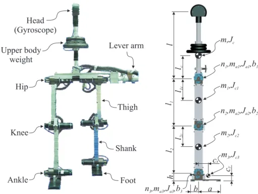
67 Figure 4.1 Seven-member biped with absolute coordinates q and control moments u. toe and heel for left and right foot. The motion of the device is shown by the (black) solid line, while the simulated response is plotted by the dashed (blue) lines. Right: CAD model - . exploded view of the knee joint: 1) encoder; 2) drive unit - engine and gear;
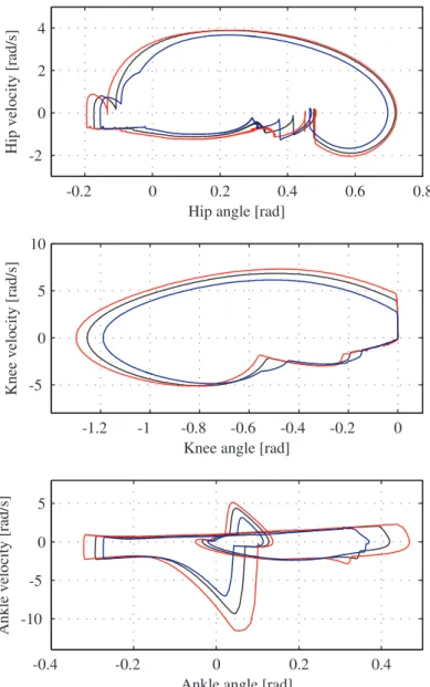
101 Figure 4.18 Phase plot corresponding to hip, knee and ankle movement to the left and. 104 Figure 4.22 Phase plot corresponding to hip, knee and ankle movement to the left and. The importance of the ZMP is that by controlling its position within a foot support area, no foot rotation will occur (ie the foot can be used as a base joint from which a trajectory tracking motion control can be performed on the body).
At the end of the spectrum of this approach is the "passive dynamic walking principle" introduced by McGear [12], by showing that (with precisely tuned design) an uncontrolled leg machine can walk on a slight downward slope (powered only by gravity) , see [13]. Goldfarb, "Experimental Implementation of Actuated Dynamic Walking in Biped Robots," The International Journal of Robotics Research - submitted.
ELIMINATING CONSTRAINT DRIFT IN THE NUMERICAL SIMULATION OF CONSTRAINED DYNAMICAL SYSTEMS
Constrained dynamical systems are traditionally modeled with a Lagrangian equation of the first kind [29], where additional algebraic variables (Lagrangian multipliers) are used to incorporate the motion constraints into the equation. Let the equation of motion for the considered system (derived using the Lagrangian formalism) be represented in the following form. To do so, let us assume that q=q(t) defines the positions of the constrained dynamical system.
Instead of (2.6), the analytical derivation of the explicit equation of constrained motion proposed by [45] is based on a velocity or acceleration level representation of the original constraints. To get a clearer interpretation, let us reformulate (2.16)2 by means of Gauss's principle of least constraint. To satisfy the (possibly dependent) position constraints, he proposed a geometrically motivated correction method based on the pseudo-inverse of the constraint matrix.
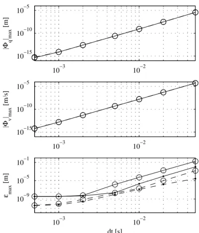
From our point of view, the primary reason for the error accumulation and constraint shift lies in the standard constraint representation (2.7). To identify the importance of the correction terms, the simulations were repeated with slightly imperfect initial conditions. Due to the large integration step, 10−2, certain constraints are not satisfied on the order of the machine precision.
In this light, regardless of the bipod configuration, the set of constraints is redundant at any point in time.
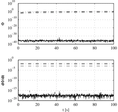
![Figure 2.1 Mathematical pendulum: l = 1m, m = 1kg. Last swing in t ∈ [0, 1000]s simulation is depicted](https://thumb-ap.123doks.com/thumbv2/123dok/10729904.0/38.892.245.639.389.628/figure-mathematical-pendulum-1kg-swing-1000-simulation-depicted.webp)
A CONTROL APPROACH FOR ACTUATED DYNAMIC WALKING IN BIPED ROBOTS
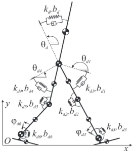
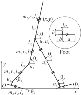
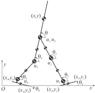
18] present a method that does not need to override the natural dynamics of the biped (depending on the choice of control parameters). The control methodology is based on a dynamic model of the robot introduced in this section. The configuration of the bipod is defined by the generalized coordinates, q= [x,y,θ,θ1,θ2,θ3,θ4,θ5,θ6]T, defined relative to the inertial reference frame.
For each segment, the moment of inertia about the center of mass of the associated link is calculated as I∗=m∗r2∗. It is important to mention that the control torques either referenced in the inertial frame or defined in the robot frame only affect the rotational dynamics of the robot. To address the issue of underactualization, we characterize the effect of the control force on the constrained bipedal motion.
To define the control measures, we impose seven state-dependent torques that directly modify the rotational dynamics of the bipod. But remember that the control philosophy in this work is to impose a minimal number of constraints and thus encourage the biped's natural dynamics rather than constrain it. Specifically, state switching occurs upon constraint configuration changes triggered by autonomous robot motion.
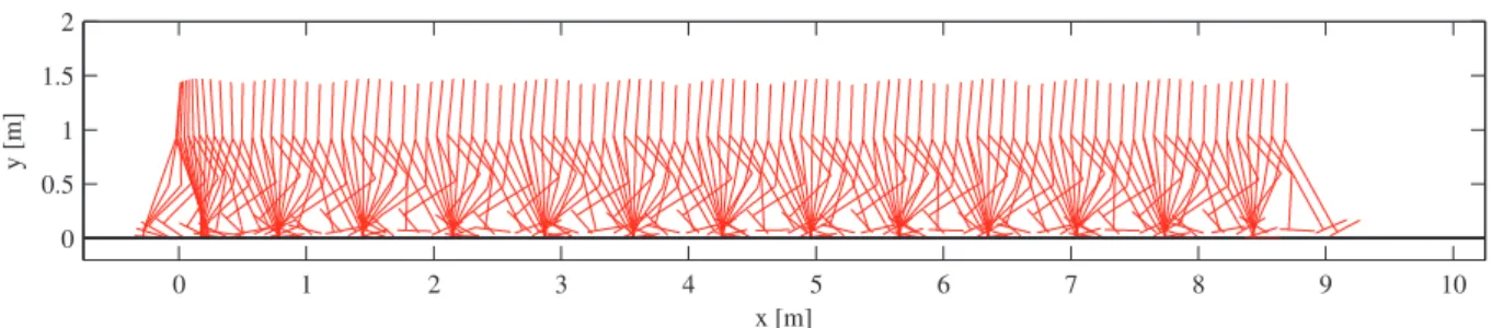
Figure 3.4 shows a strobe image of the motion results of this controller, simulated over a period of t∈[0,10]s. The corresponding real-time video of the resulting corridor is included in the supporting material. For the simulation shown, the initial configuration of the biped (starting at rest) was in the double support phase with the forward heel on the ground and the backward toe on the ground.
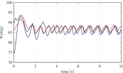
As detailed in the paper, the proposed control approach is designed to utilize the natural dynamics of the biped. Based on the simulation shown in Figure 3.4, the calculated mechanical transport cost of the proposed approach is cmt =0.19. The time evolution of the torso angle for the three passages is depicted in Figure 3.11.
The associated real-time videos in the supporting material demonstrate the rejection of the proposed approach by push-type perturbations. Realization of the corresponding torques would be made possible with additional (hip and/or ankle) actuators on the robot.
EXPERIMENTAL IMPLEMENTATION OF ACTUATED DYNAMIC WALKING IN BIPED ROBOTS
In the rest of this paper, we first recall the general idea of the control method developed by the authors [25]. The control method used in this paper requires information from the dynamic model of the biped. To ensure that A contains only the active constraints, the robot's configuration is monitored throughout the motion.
Note that using φφφ (as defined above), the generalized control force (4.4) only affects the rotational dynamics of the robot. In order to achieve walking, the control parameters are selected according to the configuration of the robot. However, depending on the robot's constraint configuration, this solution may not exist (in cases where the robot is under-activated, such as in the flight phase, or when only one toe or one heel touches the ground).
The reference position for each of the six encoders is identified (in the static position phase during initialization) using two acceleration sensors (Analog Devices, ADXL203) placed on the upper body and upper right leg. In the proposed implementation of the control, measurements of contact forces or moments are not required. For the purposes of the experimental implementation of activated dynamic walking, we consider the planar motion of the robot.
Concatenation of (4.8) and (4.9) allows reconstruction of the angular motion of the robot in the inertial frame,θθθ. This is an intrinsic property of the model that allows calculation of A(θθθ) and M(θθθ) based only on the angular configuration of the robot (i.e. calculation of (x,y) is not required). However, in the current situation, the experimental conditions will significantly change the natural dynamics of the robot proposed to be employed.
The control approach was implemented in real time and used to coordinate the walking of the bipedal robot. The black (solid) lines depict the movement of the right leg while the blue (dashed) lines depict the movement of the left leg. In addition to modifying the design of the joints, the robot's leg was also modified.
The walking experiments showed that inaccurate sensory feedback can decisively affect the performance of the robot. The experiment also verified proper coordination of the robot through short 0.1s underpowered motion phases (when only the forward heel was on the ground), see [2].
![Figure 3.13 Push experiment for the walk at [0.92, 0.81, 0.68]m/s average speeds. The six separate experiments shown characterize the response to forward and backward pushes (red and black lines respectively) at [5.1, 4,5.8]s with 200N force for a duration](https://thumb-ap.123doks.com/thumbv2/123dok/10729904.0/79.892.260.656.186.823/experiment-separate-experiments-characterize-response-backward-respectively-duration.webp)