P ART O NE
The purpose of Part One is to provide a background and context for the remainder of this book. The broad range of topics that are encompassed in the field of data and computer communications is introduced, and the fundamental concepts of protocols and protocol architectures are examined.
9
Overview
ROAD MAP FOR PART ONE
Chapter 1 Data Communications, Data Networks, and The Internet
Chapter 1 provides an overview of Parts Two through Four of the book, giving the
“big picture.” In essence, the book deals with four topics: data communications over a transmission link; wide area networks; local area networks; and protocols and the TCP/IP protocol architecture. Chapter 1 provides a preview of the first three of these topics.
Chapter 2 Protocol Architecture, TCP/IP, and Internet-Based Applications
Chapter 2 discusses the concept protocol architectures. This chapter can be read immediately following Chapter 1 or deferred until the beginning of Part Three, Four, or Five. After a general introduction, the chapter deals with the two most important protocol architectures: the Open Systems Interconnection (OSI) model and TCP/IP. Although the OSI model is often used as the framework for discourse in this area, it is the TCP/IP protocol suite that is the basis for most commercially avail- able interoperable products and that is the focus of Parts Five and Six of this book.
CHAPTER
D ATA C OMMUNICATIONS , D ATA N ETWORKS , AND THE I NTERNET
1.1 Data Communications and Networking for Today’s Enterprise 1.2 A Communications Model
1.3 Data Communications 1.4 Networks
1.5 The Internet
1.6 An Example Configuration
10
1
The 1970s and 1980s saw a merger of the fields of computer science and data communications that profoundly changed the technology, products, and compa- nies of the now combined computer-communications industry. The computer- communications revolution has produced several remarkable facts:
• There is no fundamental difference between data processing (computers) and data communications (transmission and switching equipment).
• There are no fundamental differences among data, voice, and video com- munications.
• The distinction among single-processor computer, multiprocessor computer, local network, metropolitan network, and long-haul network has blurred.
One effect of these trends has been a growing overlap of the computer and communications industries, from component fabrication to system integration.
Another result is the development of integrated systems that transmit and process all types of data and information. Both the technology and the technical standards organizations are driving toward integrated public systems that make virtually all data and information sources around the world easily and uniformly accessible.
This book aims to provide a unified view of the broad field of data and computer communications. The organization of the book reflects an attempt to break this massive subject into comprehensible parts and to build, piece by piece, a survey of the state of the art. This introductory chapter begins with a general model of communications. Then a brief discussion introduces each of the Parts Two through Four of this book. Chapter 2 provides an overview to Parts Five and Six
KEY POINTS
• The scope of this book is broad, covering three general areas: data communications, networking, and protocols; the first two are intro- duced in this chapter.
• Data communications deals with the transmission of signals in a reli- able and efficient manner. Topics covered include signal transmission, transmission media, signal encoding, interfacing, data link control, and multiplexing.
• Networking deals with the technology and architecture of the com- munications networks used to interconnect communicating devices.
This field is generally divided into the topics of local area networks (LANs) and wide area networks (WANs).
11
The fundamental problem of communication is that of reproducing at one point either exactly or approximately a message selected at another point.
—The Mathematical Theory of Communication, Claude Shannon
1.1 DATA COMMUNICATIONS AND NETWORKING FOR TODAY’S ENTERPRISE
Effective and efficient data communication and networking facilities are vital to any enterprise. In this section, we first look at trends that are increasing the challenge for the business manager in planning and managing such facilities. Then we look specif- ically at the requirement for ever-greater transmission speeds and network capacity.
Trends
Three different forces have consistently driven the architecture and evolution of data communications and networking facilities: traffic growth, development of new services, and advances in technology.
Communicationtraffic, both local (within a building or building complex) and long distance, both voice and data, has been growing at a high and steady rate for decades. The increasing emphasis on office automation, remote access, online transactions, and other productivity measures means that this trend is likely to con- tinue. Thus, managers are constantly struggling to maximize capacity and minimize transmission costs.
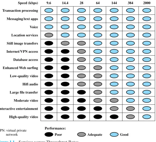
As businesses rely more and more on information technology, the range of servicesexpands. This increases the demand for high-capacity networking and trans- mission facilities. In turn, the continuing growth in high-speed network offerings with the continuing drop in prices encourages the expansion of services. Thus, growth in services and growth in traffic capacity go hand in hand. Figure 1.1 gives some examples of information-based services and the data rates needed to support them [ELSA02].
Finally, trends in technology enable the provision of increasing traffic capacity and the support of a wide range of services. Four technology trends are particularly notable:
1. The trend toward faster and cheaper, both in computing and communications, continues. In terms of computing, this means more powerful computers and clusters of computers capable of supporting more demanding applications, such as multimedia applications. In terms of communications, the increasing use of optical fiber has brought transmission prices down and greatly increased capacity. For example, for long-distance telecommunication and data network links, recent offerings of dense wavelength division multiplexing (DWDM) enable capacities of many terabits per second. For local area net- works (LANs) many enterprises now have Gigabit Ethernet backbone net- works and some are beginning to deploy 10-Gbps Ethernet.
2. Both voice-oriented telecommunications networks, such as the public switched telephone network (PSTN), and data networks, including the Internet, are more
“intelligent” than ever. Two areas of intelligence are noteworthy. First, today’s networks can offer differing levels of quality of service (QoS), which include specifications for maximum delay, minimum throughput, and so on. Second, today’s networks provide a variety of customizable services in the areas of net- work management and security.
1.1 / DATA COMMUNICATIONS AND NETWORKING FOR TODAY’S ENTERPRISE
13
9.6 Speed (kbps) Transaction processing Messaging/text apps Voice Location services Still image transfers Internet/VPN access Database access Enhanced Web surfing Low-quality video Hifi audio Large file transfer Moderate video Interactive entertainment High-quality video
Performance:
VPN: virtual private
network Poor Adequate Good
14.4 28 64 144 384 2000
Figure 1.1 Services versus Throughput Rates
1Briefly, an intranet uses Internet and Web technology in an isolated facility internal to an enterprise; an extranet extends a company’s intranet out onto the Internet to allow selected customers, suppliers, and mobile workers to access the company’s private data and applications.
3. The Internet, the Web, and associated applications have emerged as dominant features of both the business and personal world, opening up many opportunities and challenges for managers. In addition to exploiting the Internet and the Web to reach customers, suppliers, and partners, enterprises have formed intranets and extranets1to isolate their proprietary information free from unwanted access.
4. There has been a trend toward ever-increasing mobility for decades, liberating workers from the confines of the physical enterprise. Innovations include voice mail, remote data access, pagers, fax, e-mail, cordless phones, cell phones and cellular networks, and Internet portals. The result is the ability of employ- ees to take their business context with them as they move about. We are now seeing the growth of high-speed wireless access, which further enhances the ability to use enterprise information resources and services anywhere.
Data Transmission and Network Capacity Requirements
Momentous changes in the way organizations do business and process information have been driven by changes in networking technology and at the same time have driven those changes. It is hard to separate chicken and egg in this field. Similarly, the use of the Internet by both businesses and individuals reflects this cyclic depen- dency: the availability of new image-based services on the Internet (i.e., the Web) has resulted in an increase in the total number of users and the traffic volume gen- erated by each user. This, in turn, has resulted in a need to increase the speed and efficiency of the Internet. On the other hand, it is only such increased speed that makes the use of Web-based applications palatable to the end user.
In this section, we survey some of the end-user factors that fit into this equa- tion. We begin with the need for high-speed LANs in the business environment, because this need has appeared first and has forced the pace of networking develop- ment. Then we look at business WAN requirements. Finally we offer a few words about the effect of changes in commercial electronics on network requirements.
The Emergence of High-Speed LANs
Personal computers and microcom- puter workstations began to achieve widespread acceptance in business computing in the early 1980s and have now achieved virtually the status of the telephone: an essential tool for office workers. Until relatively recently, office LANs provided basic connectivity services—connecting personal computers and terminals to main- frames and midrange systems that ran corporate applications, and providing work- group connectivity at the departmental or divisional level. In both cases, traffic patterns were relatively light, with an emphasis on file transfer and electronic mail.The LANs that were available for this type of workload, primarily Ethernet and token ring, are well suited to this environment.
In the 1990s, two significant trends altered the role of the personal computer and therefore the requirements on the LAN:
1. The speed and computing power of personal computers continued to enjoy explo- sive growth. These more powerful platforms support graphics-intensive applica- tions and ever more elaborate graphical user interfaces to the operating system.
2. MIS (management information systems) organizations have recognized the LAN as a viable and essential computing platform, resulting in the focus on network computing. This trend began with client/server computing, which has become a dominant architecture in the business environment and the more recent Web- focused intranet trend. Both of these approaches involve the frequent transfer of potentially large volumes of data in a transaction-oriented environment.
The effect of these trends has been to increase the volume of data to be han- dled over LANs and, because applications are more interactive, to reduce the acceptable delay on data transfers. The earlier generation of 10-Mbps Ethernets and 16-Mbps token rings was simply not up to the job of supporting these requirements.
The following are examples of requirements that call for higher-speed LANs:
• Centralized server farms: In many applications, there is a need for user, or client, systems to be able to draw huge amounts of data from multiple central- ized servers, called server farms. An example is a color publishing operation, in
1.1 / DATA COMMUNICATIONS AND NETWORKING FOR TODAY’S ENTERPRISE
15
which servers typically contain tens of gigabytes of image data that must be downloaded to imaging workstations. As the performance of the servers them- selves has increased, the bottleneck has shifted to the network.
• Power workgroups: These groups typically consist of a small number of cooper- ating users who need to draw massive data files across the network. Examples are a software development group that runs tests on a new software version, or a computer-aided design (CAD) company that regularly runs simulations of new designs. In such cases, large amounts of data are distributed to several workstations, processed, and updated at very high speed for multiple iterations.
• High-speed local backbone: As processing demand grows, LANs proliferate at a site, and high-speed interconnection is necessary.
Corporate Wide Area Networking Needs
As recently as the early 1990s, there was an emphasis in many organizations on a centralized data processing model. In a typical environment, there might be significant computing facilities at a few regional offices, consisting of mainframes or well-equipped midrange systems. These centralized facilities could handle most corporate applications, including basic finance, accounting, and personnel programs, as well as many of the business-specific applications. Smaller, outlying offices (e.g., a bank branch) could be equipped with terminals or basic personal computers linked to one of the regional centers in a transaction-oriented environment.This model began to change in the early 1990s, and the change accelerated through the mid-1990s. Many organizations have dispersed their employees into multi- ple smaller offices. There is a growing use of telecommuting. Most significant, the nature of the application structure has changed. First client/server computing and, more recently, intranet computing have fundamentally restructured the organizational data processing environment.There is now much more reliance on personal computers, workstations, and servers and much less use of centralized mainframe and midrange systems. Furthermore, the virtually universal deployment of graphical user interfaces to the desktop enables the end user to exploit graphic applications, multimedia, and other data-intensive applications. In addition, most organizations require access to the Inter- net. When a few clicks of the mouse can trigger huge volumes of data, traffic patterns have become more unpredictable while the average load has risen.
All of these trends means that more data must be transported off premises and into the wide area. It has long been accepted that in the typical business environ- ment, about 80% of the traffic remains local and about 20% traverses wide area links. But this rule no longer applies to most companies, with a greater percentage of the traffic going into the WAN environment [COHE96]. This traffic flow shift places a greater burden on LAN backbones and, of course, on the WAN facilities used by a corporation. Thus, just as in the local area, changes in corporate data traffic patterns are driving the creation of high-speed WANs.
Digital Electronics
The rapid conversion of consumer electronics to digital technology is having an impact on both the Internet and corporate intranets. As these new gadgets come into view and proliferate, they dramatically increase the amount of image and video traffic carried by networks.Two noteworthy examples of this trend are digital versatile disks (DVDs) and digital still cameras. With the capacious DVD, the electronics industry has at last
found an acceptable replacement for the analog VHS videotape. The DVD has replaced the videotape used in videocassette recorders (VCRs) and replaced the CD-ROM in personal computers and servers. The DVD takes video into the digital age. It delivers movies with picture quality that outshines laser disks, and it can be randomly accessed like audio CDs, which DVD machines can also play. Vast vol- umes of data can be crammed onto the disk, currently seven times as much as a CD- ROM. With DVD’s huge storage capacity and vivid quality, PC games have become more realistic and educational software incorporates more video. Following in the wake of these developments is a new crest of traffic over the Internet and corporate intranets, as this material is incorporated into Web sites.
A related product development is the digital camcorder. This product has made it easier for individuals and companies to make digital video files to be placed on corporate and Internet Web sites, again adding to the traffic burden.
1.2 A COMMUNICATIONS MODEL
This section introduces a simple model of communications, illustrated by the block diagram in Figure 1.2a.
The fundamental purpose of a communications system is the exchange of data between two parties. Figure 1.2b presents one particular example, which is commu- nication between a workstation and a server over a public telephone network.
Another example is the exchange of voice signals between two telephones over the same network. The key elements of the model are as follows:
• Source. This device generates the data to be transmitted; examples are tele- phones and personal computers.
Server Modem
Modem
Public telephone network Workstation
Source Trans-
mitter
Trans- mission System
Receiver Destination
Source system Destination system
(a) General block diagram
(b) Example Figure 1.2 Simplified Communications Model
1.2 / A COMMUNICATIONS MODEL
17
• Transmitter: Usually, the data generated by a source system are not transmit- ted directly in the form in which they were generated. Rather, a transmitter transforms and encodes the information in such a way as to produce electro- magnetic signals that can be transmitted across some sort of transmission sys- tem. For example, a modem takes a digital bit stream from an attached device such as a personal computer and transforms that bit stream into an analog sig- nal that can be handled by the telephone network.
• Transmission system: This can be a single transmission line or a complex net- work connecting source and destination.
• Receiver: The receiver accepts the signal from the transmission system and converts it into a form that can be handled by the destination device. For example, a modem will accept an analog signal coming from a network or transmission line and convert it into a digital bit stream.
• Destination: Takes the incoming data from the receiver.
This simple narrative conceals a wealth of technical complexity. To get some idea of the scope of this complexity, Table 1.1 lists some of the key tasks that must be performed in a data communications system. The list is somewhat arbitrary: Ele- ments could be added; items on the list could be merged; and some items represent several tasks that are performed at different “levels” of the system. However, the list as it stands is suggestive of the scope of this book.
The first item, transmission system utilization, refers to the need to make efficient use of transmission facilities that are typically shared among a number of communicating devices. Various techniques (referred to as multiplexing) are used to allocate the total capacity of a transmission medium among a number of users.
Congestion control techniques may be required to assure that the system is not overwhelmed by excessive demand for transmission services.
To communicate, a device must interfacewith the transmission system. All the forms of communication discussed in this book depend on the use of electromagnetic signals propagated over a transmission medium. Thus, once an interface is estab- lished,signal generationis required for communication. The properties of the signal, such as form and intensity, must be such that the signal is (1) capable of being propa- gated through the transmission system, and (2) interpretable as data at the receiver.
Not only must the signals be generated to conform to the requirements of the transmission system and receiver, but also there must be some form of synchronization
Table 1.1 Communications Tasks
Transmission system utilization Addressing
Interfacing Routing
Signal generation Recovery
Synchronization Message formatting
Exchange management Security
Error detection and correction Network management
Flow control
between transmitter and receiver.The receiver must be able to determine when a signal begins to arrive and when it ends. It must also know the duration of each signal element.
Beyond the basic matter of deciding on the nature and timing of signals, there is a variety of requirements for communication between two parties that might be col- lected under the term exchange management. If data are to be exchanged in both directions over a period of time, the two parties must cooperate. For example, for two parties to engage in a telephone conversation, one party must dial the number of the other, causing signals to be generated that result in the ringing of the called phone.The called party completes a connection by lifting the receiver. For data processing devices, more will be needed than simply establishing a connection; certain conven- tions must be decided on. These conventions may include whether both devices may transmit simultaneously or must take turns, the amount of data to be sent at one time, the format of the data, and what to do if certain contingencies such as an error arise.
The next two items might have been included under exchange management, but they seem important enough to list separately. In all communications systems, there is a potential for error; transmitted signals are distorted to some extent before reaching their destination.Error detection and correctionare required in circum- stances where errors cannot be tolerated. This is usually the case with data process- ing systems. For example, in transferring a file from one computer to another, it is simply not acceptable for the contents of the file to be accidentally altered.Flow controlis required to assure that the source does not overwhelm the destination by sending data faster than they can be processed and absorbed.
Next are the related but distinct concepts of addressing and routing. When more than two devices share a transmission facility, a source system must indicate the identity of the intended destination. The transmission system must assure that the destination system, and only that system, receives the data. Further, the trans- mission system may itself be a network through which various paths may be taken.
A specific route through this network must be chosen.
Recoveryis a concept distinct from that of error correction. Recovery techniques are needed in situations in which an information exchange, such as a database transac- tion or file transfer, is interrupted due to a fault somewhere in the system.The objective is either to be able to resume activity at the point of interruption or at least to restore the state of the systems involved to the condition prior to the beginning of the exchange.
Message formattinghas to do with an agreement between two parties as to the form of the data to be exchanged or transmitted, such as the binary code for characters.
Frequently, it is important to provide some measure of securityin a data com- munications system. The sender of data may wish to be assured that only the intended receiver actually receives the data. And the receiver of data may wish to be assured that the received data have not been altered in transit and that the data actually come from the purported sender.
Finally, a data communications facility is a complex system that cannot create or run itself.Network managementcapabilities are needed to configure the system, mon- itor its status, react to failures and overloads, and plan intelligently for future growth.
Thus, we have gone from the simple idea of data communication between source and destination to a rather formidable list of data communications tasks. In this book, we elaborate this list of tasks to describe and encompass the entire set of activities that can be classified under data and computer communications.
1.3 / DATA COMMUNICATIONS
19 1.3 DATA COMMUNICATIONS
Following Part One, this book is organized into five parts. Part Two deals with the most fundamental aspects of the communications function, focusing on the trans- mission of signals in a reliable and efficient manner. For want of a better name, we have given Part Two the title “Data Communications,” although that term arguably encompasses some or even all of the topics of Parts Three through Six.
A Data Communications Model
To get some flavor for the focus of Part Two, Figure 1.3 provides a new perspective on the communications model of Figure 1.2a. We trace the details of this figure using electronic mail as an example.
Suppose that the input device and transmitter are components of a personal computer. The user of the PC wishes to send a message mto another user. The user activates the electronic mail package on the PC and enters the message via the key- board (input device). The character string is briefly buffered in main memory. We can view it as a sequence of bits (g) in memory. The personal computer is connected to some transmission medium, such as a local network or a telephone line, by an I/O device (transmitter), such as a local network transceiver or a modem. The input data are transferred to the transmitter as a sequence of voltage shifts [g(t)] representing bits on some communications bus or cable. The transmitter is connected directly to the medium and converts the incoming stream [g(t)] into a signal [s(t)] suitable for transmission; specific alternatives will be described in Chapter 5.
The transmitted signal s(t) presented to the medium is subject to a number of impairments, discussed in Chapter 3, before it reaches the receiver. Thus, the received signal r(t) may differ from s(t). The receiver will attempt to estimate the original s(t), based on r(t) and its knowledge of the medium, producing a sequence of bits These bits are sent to the output personal computer, where they are briefly buffered in memory as a block of bits In many cases, the destination system will attempt to determine if an error has occurred and, if so, cooperate with the source system to eventually obtain a complete, error-free block of data. These data are then presented to the user via an output device, such as a
1g¿2. g¿1t2.
1 2 3 4 5 6
Input information
m
Input data g(t)
Transmitted signal
s(t)
Received signal
r(t)
Output data g'(t)
Output information
m'
Source Trans-
mitter
Trans- mission System
Receiver Destination
Text Text
Digital bit stream
Analog signal
Digital bit stream Analog
signal
Figure 1.3 Simplified Data Communications Model
printer or screen. The message as viewed by the user will usually be an exact copy of the original message (m).
Now consider a telephone conversation. In this case the input to the telephone is a message (m) in the form of sound waves. The sound waves are converted by the telephone into electrical signals of the same frequency. These signals are transmitted without modification over the telephone line. Hence the input signal g(t) and the transmitted signal s(t) are identical. The signals (t) will suffer some distortion over the medium, so that r(t) will not be identical to s(t). Nevertheless, the signal r(t) is converted back into a sound wave with no attempt at correction or improvement of signal quality. Thus, is not an exact replica of m. However, the received sound message is generally comprehensible to the listener.
The discussion so far does not touch on other key aspects of data communica- tions, including data link control techniques for controlling the flow of data and detect- ing and correcting errors, and multiplexing techniques for transmission efficiency.
The Transmission of Information
The basic building block of any communications facility is the transmission line.
Much of the technical detail of how information is encoded and transmitted across a line is of no real interest to the business manager. The manager is concerned with whether the particular facility provides the required capacity, with acceptable relia- bility, at minimum cost. However, there are certain aspects of transmission technol- ogy that a manager must understand to be able to ask the right questions and make informed decisions.
One of the basic choices facing a business user is the transmission medium. For use within the business premises, this choice is generally completely up to the busi- ness. For long-distance communications, the choice is generally but not always made by the long-distance carrier. In either case, changes in technology are rapidly chang- ing the mix of media used. Of particular note are fiber optic transmission and wirelesstransmission (e.g., satellite and radio). These two media are now driving the evolution of data communications transmission.
The ever-increasing capacity of fiber optic channels is making channel capac- ity a virtually free resource. The growth of the market for optical fiber transmission systems since the beginning of the 1980s is without precedent. During the past 10 years, the cost of fiber optic transmission has dropped by more than an order of magnitude, and the capacity of such systems has grown at almost as rapid a rate.
Long-distance telephone communications trunks within the United States will soon consist almost completely of fiber optic cable. Because of its high capacity and because of its security characteristics—fiber is almost impossible to tap—it is becoming increasingly used within office buildings to carry the growing load of busi- ness information. However, switching is now becoming the bottleneck. This problem is causing radical changes in communications architecture, including asynchronous transfer mode (ATM) switching, highly parallel processing in switches, and inte- grated network management schemes.
The second medium—wireless transmission—is a result of the trend toward universal personal telecommunications and universal access to communications.
The first concept refers to the ability of a person to identify himself or herself easily m¿
1m¿2
1.3 / DATA COMMUNICATIONS
21
and to use conveniently any communication system in a large area (e.g., globally, over a continent, or in an entire country) in terms of a single account. The second refers to the capability of using one’s terminal in a wide variety of environments to connect to information services (e.g., to have a portable terminal that will work in the office, on the street, and on airplanes equally well). This revolution in personal computing obviously involves wireless communication in a fundamental way.
Despite the growth in the capacity and the drop in cost of transmission facili- ties, transmission services remain the most costly component of a communications budget for most businesses. Thus, the manager needs to be aware of techniques that increase the efficiency of the use of these facilities. The two major approaches to greater efficiency are multiplexing and compression.Multiplexingrefers to the abil- ity of a number of devices to share a transmission facility. If each device needs the facility only a fraction of the time, then a sharing arrangement allows the cost of the facility to be spread over many users.Compression, as the name indicates, involves squeezing the data down so that a lower-capacity, cheaper transmission facility can be used to meet a given demand. These two techniques show up separately and in combination in a number of types of communications equipment. The manager needs to understand these technologies to be able to assess the appropriateness and cost-effectiveness of the various products on the market.
Transmission and Transmission Media
Information can be communicated by converting it into an electromagnetic signal and transmitting that signal over some medium, such as a twisted-pair telephone line. The most commonly used transmis- sion media are twisted-pair lines, coaxial cable, optical fiber cable, and terrestrial and satellite microwave. The data rates that can be achieved and the rate at which errors can occur depend on the nature of the signal and the type of medium. Chapters 3 and 4 examine the significant properties of electromagnetic signals and compare the var- ious transmission media in terms of cost, performance, and applications.Communication Techniques
The transmission of information across a trans- mission medium involves more than simply inserting a signal on the medium. The technique used to encode the information into an electromagnetic signal must be determined. There are various ways in which the encoding can be done, and the choice affects performance and reliability. Furthermore, the successful transmission of information involves a high degree of cooperation between the various compo- nents. The interface between a device and the transmission medium must be agreed on. Some means of controlling the flow of information and recovering from its loss or corruption must be used. These latter functions are performed by a data link con- trol protocol. All these issues are examined in Chapters 5 through 7.Transmission Efficiency
A major cost in any computer/communications facility is transmission cost. Because of this, it is important to maximize the amount of infor- mation that can be carried over a given resource or, alternatively, to minimize the transmission capacity needed to satisfy a given information communications require- ment. Two ways of achieving this objective are multiplexing and compression. The two techniques can be used separately or in combination. Chapter 8 examines the three most common multiplexing techniques—frequency division, synchronous time divi- sion, and statistical time division—as well as the important compression techniques.1.4 NETWORKS
The number of computers in use worldwide is in the hundreds of millions. More- over, the expanding memory and processing power of these computers means that users can put the machines to work on new kinds of applications and functions.
Accordingly, the pressure from the users of these systems for ways to communicate among all these machines is irresistible. It is changing the way vendors think and the way all automation products and services are sold. This demand for connectivity is manifested in two specific requirements: the need for communications software, which is previewed in the next section, and the need for networks.
One type of network that has become ubiquitous is the local area network (LAN). Indeed, the LAN is to be found in virtually all medium- and large-size office buildings. As the number and power of computing devices have grown, so have the number and capacity of LANs to be found in an office. Although standards have been developed that reduce somewhat the number of types of LANs, there are still half a dozen general types of local area networks to choose from. Furthermore, many offices need more than one such network, with the attendant problems of intercon- necting and managing a diverse collection of networks, computers, and terminals.
Beyond the confines of a single office building, networks for voice, data, image, and video are equally important to business. Here, too, there are rapid changes.
Advances in technology have led to greatly increased capacity and the concept of integration.Integrationmeans that the customer equipment and networks can deal simultaneously with voice, data, image, and even video. Thus, a memo or report can be accompanied by voice commentary, presentation graphics, and perhaps even a short video introduction or summary. Image and video services impose large demands on wide area network transmission. Moreover, as LANs become ubiqui- tous and as their transmission rates increase, the demands on the wide area networks to support LAN interconnection have increased the demands on wide area network capacity and switching. On the other hand, fortunately, the enormous and ever- increasing capacity of fiber optic transmission provides ample resources to meet these demands. However, developing switching systems with the capacity and rapid response to support these increased requirements is a challenge not yet conquered.
The opportunities for using networks as an aggressive competitive tool and as a means of enhancing productivity and slashing costs are great. The manager who understands the technology and can deal effectively with vendors of service and equipment is able to enhance a company’s competitive position.
In the remainder of this section, we provide a brief overview of various net- works. Parts Three and Four cover these topics in depth.
Wide Area Networks
Wide area networks generally cover a large geographical area, require the crossing of public right-of-ways, and rely at least in part on circuits provided by a common carrier. Typically, a WAN consists of a number of interconnected switching nodes. A transmission from any one device is routed through these internal nodes to the specified destination device. These nodes (including the boundary nodes) are not
1.4 / NETWORKS
23
concerned with the content of the data; rather, their purpose is to provide a switching facility that will move the data from node to node until they reach their destination.
Traditionally, WANs have been implemented using one of two technologies:
circuit switching and packet switching. More recently, frame relay and ATM net- works have assumed major roles.
Circuit Switching
In a circuit-switching network, a dedicated communications path is established between two stations through the nodes of the network. That path is a connected sequence of physical links between nodes. On each link, a logi- cal channel is dedicated to the connection. Data generated by the source station are transmitted along the dedicated path as rapidly as possible. At each node, incoming data are routed or switched to the appropriate outgoing channel without delay. The most common example of circuit switching is the telephone network.Packet Switching
A quite different approach is used in a packet-switching net- work. In this case, it is not necessary to dedicate transmission capacity along a path through the network. Rather, data are sent out in a sequence of small chunks, called packets. Each packet is passed through the network from node to node along some path leading from source to destination. At each node, the entire packet is received, stored briefly, and then transmitted to the next node. Packet-switching networks are commonly used for terminal-to-computer and computer-to-computer communications.Frame Relay
Packet switching was developed at a time when digital long- distance transmission facilities exhibited a relatively high error rate compared to today’s facilities. As a result, there is a considerable amount of overhead built into packet-switching schemes to compensate for errors. The overhead includes addi- tional bits added to each packet to introduce redundancy and additional processing at the end stations and the intermediate switching nodes to detect and recover from errors.With modern high-speed telecommunications systems, this overhead is unnec- essary and counterproductive. It is unnecessary because the rate of errors has been dramatically lowered and any remaining errors can easily be caught in the end sys- tems by logic that operates above the level of the packet-switching logic. It is coun- terproductive because the overhead involved soaks up a significant fraction of the high capacity provided by the network.
Frame relay was developed to take advantage of these high data rates and low error rates. Whereas the original packet-switching networks were designed with a data rate to the end user of about 64 kbps, frame relay networks are designed to operate efficiently at user data rates of up to 2 Mbps. The key to achieving these high data rates is to strip out most of the overhead involved with error control.
ATM
Asynchronous transfer mode (ATM), sometimes referred to as cell relay, is a culmination of developments in circuit switching and packet switching. ATM can be viewed as an evolution from frame relay. The most obvious difference between frame relay and ATM is that frame relay uses variable-length packets, called frames, and ATM uses fixed-length packets, called cells. As with frame relay, ATM provides little overhead for error control, depending on the inherentreliability of the transmission system and on higher layers of logic in the end sys- tems to catch and correct errors. By using a fixed packet length, the processing overhead is reduced even further for ATM compared to frame relay. The result is that ATM is designed to work in the range of 10s and 100s of Mbps, and in the Gbps range.
ATM can also be viewed as an evolution from circuit switching. With circuit switching, only fixed-data-rate circuits are available to the end system. ATM allows the definition of multiple virtual channels with data rates that are dynami- cally defined at the time the virtual channel is created. By using small, fixed-size cells, ATM is so efficient that it can offer a constant-data-rate channel even though it is using a packet-switching technique. Thus, ATM extends circuit switch- ing to allow multiple channels with the data rate on each channel dynamically set on demand.
Local Area Networks
As with WANs, a LAN is a communications network that interconnects a variety of devices and provides a means for information exchange among those devices. There are several key distinctions between LANs and WANs:
1. The scope of the LAN is small, typically a single building or a cluster of build- ings. This difference in geographic scope leads to different technical solutions, as we shall see.
2. It is usually the case that the LAN is owned by the same organization that owns the attached devices. For WANs, this is less often the case, or at least a significant fraction of the network assets is not owned. This has two implications. First, care must be taken in the choice of LAN, because there may be a substantial capital investment (compared to dial-up or leased charges for WANs) for both purchase and maintenance. Second, the network management responsibility for a LAN falls solely on the user.
3. The internal data rates of LANs are typically much greater than those of WANs.
LANs come in a number of different configurations. The most common are switched LANs and wireless LANs. The most common switched LAN is a switched Ethernet LAN, which may consist of a single switch with a number of attached devices, or a number of interconnected switches. Two other prominent examples are ATM LANs, which simply use an ATM network in a local area, and Fibre Channel.
Wireless LANs use a variety of wireless transmission technologies and organiza- tions. LANs are examined in depth in Part Four.
Wireless Networks
As was just mentioned, wireless LANs are common are widely used in business environments. Wireless technology is also common for both wide area voice and data networks. Wireless networks provide advantages in the areas of mobility and ease of installation and configuration. Chapters 14 and 17 deal with wireless WANs and LANs, respectively.
1.5 / THE INTERNET
25 1.5 THE INTERNET
Origins of the Internet
The Internet evolved from the ARPANET, which was developed in 1969 by the Advanced Research Projects Agency (ARPA) of the U.S. Department of Defense.
It was the first operational packet-switching network. ARPANET began operations in four locations. Today the number of hosts is in the hundreds of millions, the num- ber of users in the billions, and the number of countries participating nearing 200.
The number of connections to the Internet continues to grow exponentially.
The network was so successful that ARPA applied the same packet-switching technology to tactical radio communication (packet radio) and to satellite com- munication (SATNET). Because the three networks operated in very different communication environments, the appropriate values for certain parameters, such as maximum packet size, were different in each case. Faced with the dilemma of integrating these networks, Vint Cerf and Bob Kahn of ARPA started to develop methods and protocols for internetworking; that is, communicating across arbi- trary, multiple, packet-switched networks. They published a very influential paper in May of 1974 [CERF74] outlining their approach to a Transmission Control Pro- tocol. The proposal was refined and details filled in by the ARPANET community, with major contributions from participants from European networks, such as Cyclades (France), and EIN, eventually leading to the TCP (Transmission Control Protocol) and IP (Internet Protocol) protocols, which, in turn, formed the basis for what eventually became the TCP/IP protocol suite. This provided the foundation for the Internet.
Key Elements
Figure 1.4 illustrates the key elements that comprise the Internet. The purpose of the Internet, of course, is to interconnect end systems, called hosts; these include PCs, workstations, servers, mainframes, and so on. Most hosts that use the Internet are connected to a network, such as a local area network (LAN) or a wide area net- work (WAN). These networks are in turn connected by routers. Each router attaches to two or more networks. Some hosts, such as mainframes or servers, con- nect directly to a router rather than through a network.
In essence, the Internet operates as follows. A host may send data to another host anywhere on the Internet. The source host breaks the data to be sent into a sequence of packets, called IP datagramsor IP packets. Each packet includes a unique numeric address of the destination host. This address is referred to as an IP address, because the address is carried in an IP packet. Based on this destination address, each packet travels through a series of routers and networks from source to destination. Each router, as it receives a packet, makes a routing decision and for- wards the packet along its way to the destination.
Internet Architecture
The Internet today is made up of thousands of overlapping hierarchical networks.
Because of this, it is not practical to attempt a detailed description of the exact
Ethernet switch Ethernet
switch Router
Router Standalone
mainframe
Router
Router Wide area network
(e.g., ATM) Local area
network
Local area network Wide area network
(e.g., ATM)
Information server
LAN PCs and workstations Figure 1.4 Key Elements of the Internet
architecture or topology of the Internet. However, an overview of the common, gen- eral characteristics can be made. Figure 1.5 illustrates the discussion and Table 1.2 summarizes the terminology.
A key element of the Internet is the set of hosts attached to it. Simply put, a host is a computer. Today, computers come in many forms, including mobile phones and even cars. All of these forms can be hosts on the Internet. Hosts are sometimes grouped together in a LAN. This is the typical configuration in a corporate environ- ment. Individual hosts and LANs are connected to an Internet service provider (ISP)through a point of presence (POP). The connection is made in a series of steps starting with the customer premises equipment (CPE). The CPE is the communica- tions equipment located onsite with the host.
For many home users, the CPE is a 56-kbps modem. This is perfectly adequate for e-mail and related services but marginal for graphics-intensive Web surfing.
Newer CPE offerings provide greater capacity and guaranteed service in some cases. A sample of these new access technologies includes DSL, cable modem, and satellite. Users who connect to the Internet through their work often use worksta- tions or PCs connected to their employer-owned LANs, which in turn connect through shared organizational trunks to an ISP. In these cases the shared circuit is often a T-1 connection (1.544 Mbps), while for very large organizations T-3 connec- tions (44.736 Mbps) are sometimes found. Alternatively, an organization’s LAN
1.5 / THE INTERNET
27
Backbone ISP
Backbone ISP
Regional ISP LAN
switch
Corporate LAN
Corporate LAN Residential
subscribers
Server
Server
Server ISP Web Regional farm
ISP Private peering
Regional ISP
Open circle NAP Filled circle POP Figure 1.5 Simplified View of Portion of Internet
may be hooked to a wide area network (WAN), such as a frame relay network, which in turn connects to an ISP.
The CPE is physically attached to the “local loop” or “last mile.”This is the infra- structure between a provider’s installation and the site where the host is located. For example, a home user with a 56K modem attaches the modem to the telephone line.
The telephone line is typically a pair of copper wires that runs from the house to a central office (CO)owned and operated by the telephone company. In this instance the local loop is the pair of copper wires running between the home and the CO. If the home user has a cable modem, the local loop is the coaxial cable that runs from the home to the cable company facilities. The preceding examples are a bit of an over- simplification, but they suffice for this discussion. In many cases the wires that leave a home are aggregated with wires from other homes and then converted to a different media such as fiber. In these cases the term local loopstill refers to the path from the home to the CO or cable facility. The local loop provider is not necessarily the ISP. In many cases the local loop provider is the telephone company and the ISP is a large, national service organization. Often, however, the local loop provider is also the ISP.
The ISP provides access to its larger network through a POP. A POP is simply a facility where customers can connect to the ISP network. The facility is sometimes owned by the ISP, but often the ISP leases space from the local loop carrier. A POP can be as simple as a bank of modems and an access server installed in a rack at the CO. The POPs are usually spread out over the geographic area where the provider
Table 1.2 Internet Terminology
Central Office (CO)
The place where telephone companies terminate customer lines and locate switching equipment to interconnect those lines with other networks.
Customer Premises Equipment (CPE)
Telecommunications equipment that is located on the customer’s premises (physical location) rather than on the provider’s premises or in between. Telephone handsets, modems, cable TV set-top boxes, and digital subscriber line routers are examples. Historically, this term referred to equipment placed at the customer’s end of the telephone line and usually owned by the telephone company. Today, almost any end-user equipment can be called customer premises equipment and it can be owned by the customer or by the provider.
Internet Service Provider (ISP)
A company that provides other companies or individuals with access to, or presence on, the Internet. An ISP has the equipment and the telecommunication line access required to have a POP on the Internet for the geographic area served. The larger ISPs have their own high-speed leased lines so that they are less dependent on the telecommunication providers and can provide better service to their customers.
Network Access Point (NAP)
In the United States, a network access point (NAP) is one of several major Internet interconnection points that serve to tie all the ISPs together. Originally, four NAPs—in New York, Washington, D.C., Chicago, and San Francisco—were created and supported by the National Science Foundation as part of the transition from the original U.S. government—financed Internet to a commercially operated Internet. Since that time, several new NAPs have arrived, including WorldCom’s “MAE West” site in San Jose, California and ICS Network Systems’
“Big East.”
The NAPs provide major switching facilities that serve the public in general. Companies apply to use the NAP facilities. Much Internet traffic is handled without involving NAPs, using peering arrangements and interconnections within geographic regions.
Network Service Provider (NSP)
A company that provides backbone services to an Internet service provider (ISP). Typically, an ISP connects at a point called an Internet exchange (IX) to a regional ISP that in turn connects to an NSP backbone.
Point of Presence (POP)
A site that has a collection of telecommunications equipment, usually refers to ISP or telephone company sites. An ISP POP is the edge of the ISP’s network; connections from users are accepted and authenticated here. An Internet access provider may operate several POPs distributed throughout its area of operation to increase the chance that their subscribers will be able to reach one with a local telephone call. The largest national ISPs have POPs all over the country.
offers service. The ISP acts as a gateway to the Internet, providing many important services. For most home users, the ISP provides the unique numeric IP address needed to communicate with other Internet hosts. Most ISPs also provide name res- olution and other essential network services. The most important service an ISP pro- vides, though, is access to other ISP networks. Access is facilitated by formal peering agreements between providers. Physical access can be implemented by connecting POPs from different ISPs. This can be done directly with a local connection if the POPs are collocated or with leased lines when the POPs are not collocated. A more commonly used mechanism is the network access point (NAP).
A NAP is a physical facility that provides the infrastructure to move data between connected networks. In the United States, the National Science Foundation (NSF) privatization plan called for the creation of four NAPs. The NAPs were built and are operated by the private sector. The number of NAPs has grown significantly
1.6 / AN EXAMPLE CONFIGURATION
29
over the years, and the technology employed has shifted from Fiber Distributed Data Interface (FDDI) and Ethernet to ATM and Gigabit Ethernet. Most NAPs today have an ATM core. The networks connected at a NAP are owned and oper- ated by network service providers (NSPs). A NSP can also be an ISP but this is not always the case. Peering agreements are between NSPs and do not include the NAP operator. The NSPs install routers at the NAP and connect them to the NAP infra- structure. The NSP equipment is responsible for routing, and the NAP infrastructure provides the physical access paths between routers.
A small hypothetical example can help make the picture clearer. In this exam- ple there are two companies, one named A, Inc. and the other B, Inc. and they are both NSPs. A, Inc. and B, Inc. have a peering agreement and they both install routers in two NAPs, one located on the east coast of the United States and the other on the west coast. There are also two other companies known as Y, Inc. and Z, Inc. and they are both ISPs. Finally, there is a home user named Bob and a small company named Small, Inc.
Small, Inc. has four hosts connected together into a LAN. Each of the four hosts can communicate and share resources with the other three. Small, Inc. would like access to a broader set of services so they contract with ISP Y, Inc. for a connec- tion. Small, Inc. installs a CPE to drive a leased T-1 line into a Y, Inc. POP. Once the CPE is connected, software automatically assigns a numeric address to each Small, Inc. host. The Small, Inc. hosts can now communicate and share resources with any other host connected to the larger ISP network. On the other side of the country, Bob decides to contract with ISP Z, Inc. He installs a modem on his phone line to dial into a Z, Inc. POP. Once the modem connects, a numeric address is automati- cally assigned to his home computer. His computer can now communicate and share resources with any other computer connected to the larger ISP network.
Bob’s home machine and the hosts owned by Small, Inc. cannot yet communi- cate. This becomes possible when their respective ISPs contract with NSPs that have a peering agreement. In this example, the ISP Y, Inc. decides to expand its service coverage to the opposite coast and contracts with the NSP A, Inc. A, Inc. sells band- width on its high-speed coast-to-coast network. The ISP Z, Inc. also wishes to expand its service coverage and contracts with the NSP B, Inc. Like A, Inc., B, Inc. also sells bandwidth on a high-speed coast-to-coast network. Because A, Inc. and B, Inc. have a peering agreement and have implemented the agreement at two NAPs, Bob’s home machine and the hosts of Small, Inc. can now communicate and share resources.
Although this example is contrived, in principle this is what the Internet is. The dif- ferences are that the Internet has millions of hosts and many thousands of networks using dozens of access technologies, including satellite, radio, leased T-1, and DSL.
1.6 AN EXAMPLE CONFIGURATION
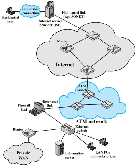
To give some feel for the scope of concerns of Parts Two through Four, Figure 1.6 illustrates some of the typical communications and network elements in use today.
In the upper-left-hand portion of the figure, we see an individual residential user connected to an Internet service provider (ISP) through some sort of subscriber connection. Common examples of such a connection are the public telephone
Internet
Router
Router Ethernet
switch
Information server Firewall
host
High-speed link (e.g., SONET)
LAN PCs and workstations
Private WAN
ATM network
ATM switch
High-speed link Subscriber connection Residential
user Internet service
provider (ISP)
Figure 1.6 A Networking Configuration
network, for which the user requires a dial-up modem (e.g. a 56-kbps modem); a dig- ital subscriber line (DSL), which provides a high-speed link over telephone lines and requires a special DSL modem; and a cable TV facility, which requires a cable modem. In each case, there are separate issues concerning signal encoding, error control, and the internal structure of the subscribe network.
Typically, an ISP will consist of a number of interconnected servers (only a single server is shown) connected to the Internet through a high-speed link. One example of such a link is a SONET (synchronous optical network) line, described in Chapter 8. The Internet consists of a number of interconnected routers that span the globe. The routers forward packets of data from source to destination through the Internet.
1.6 / AN EXAMPLE CONFIGURATION
31
The lower portion of Figure 1.6 shows a LAN implemented using a single Ethernet switch. This is a common configuration at a small business or other small organization. The LAN is connected to the Internet through a firewall host that pro- vides security services. In this example the firewall connects to the Internet through an ATM network. There is also a router off of the LAN hooked into a private WAN, which might be a private ATM or frame relay network.
A variety of design issues, such as signal encoding and error control, relate to the links between adjacent elements, such as between routers on the Internet or between switches in the ATM network, or between a subscriber and an ISP. The internal structure of the various networks (telephone, ATM, Ethernet) raises addi- tional issues. We will be occupied in Parts Two through Four with the design features suggested by Figure 1.6.