83
THE DESIGN OF THE CONSTRUCTION OF RETAINING WALLS ON THE RIVER SLOPES OF KUIN
Achmad Yasrifullah and Adriani
Civil Engineering Major, Faculty of Engineering, Lambung Mangkurat University email: [email protected]
ABSTRACT
North Kuin Street, North Kuin, North Banjarmasin Subdistrict, South Kalimantan Sub-district is right on the outskirts of Kuin River. Precisely the road that is in front of the Sultan Suriansyah Mosque, where the road has experienced cracks that can potentially occur landslides. In the event of an avalanche, it will result in obstructed traffic activities on the road which also affect the economy of the surrounding community. So from that the soil retaining wall is needed to maintain the stability of the land on the outskirts of the Kuin River so that landslides do not occur.
This design begins with identifying problems that occur. Next is data collection of investigations in the field and laboratory. Then the data obtained are analyzed and interpreted and then visualized in the form of stratigraphy by plotting the type of soil by the results of sondir and boring that have been interpreted. After that, check the initial condition of the slope so that the shape of the avalanche can be identified. Then proceed with calculating the forces acting on the retaining wall due to traffic loads and other loads above it to obtain carrying capacity from the ground. Then proceed with modeling and analysis using Geo Studio 2012 software to see the value of SF (safety factor). At the end of the calculation the volume and price of the work unit are calculated to obtain the amount of the budget plan (RAB).
From the results of the analysis of the design of anchor plaster, it was obtained a box profile of FSP VIL steel plaster with a total length of 28 m plaster. At stake uses a steel pipe with a diameter of 91.44 cm which is set at a depth of 28 m. For slope stability with pile reinforcement obtained SF = 1.835> 1.5, it can be said to be safe.
Based on the calculation of the volume and price of the work unit, this design requires a cost of Rp. 7,340,166,486, -
Keyword : Landslide, Retaining Wall, Design Of Plaster
84 1. Introduction
1.1 Background
Banjarmasin is one of the cities in Indonesia that has many rivers in several areas. Therefore, in the city of Banjarmasin, there are many roads on the banks of the river. One of them is North Kuin Road; this road is on the edge of the Kuin River. Precisely in front of the Sultan Suriansyah Mosque, where roads in the surrounding area have cracks that have the potential for landslides. This event can be influenced by several factors. The main factors that influence are erosion / scour due to the flow of the Kuin River which causes a lot of soil mass to be washed away, so that the mass resistance of the soil will decrease which results in damage to the road. Another factor that affects road damage is that the load passing over it is too heavy.
The design and manufacture of retaining walls in the area of road damage is the right solution. This design aims to be able to support the soil on the road and function to hold the soil and prevent the danger of landslides due to water loads, soil weight and the load that works. The retaining wall can be said to be safe if the retaining wall has been considered for its safety factor, both against the danger of shifting, the danger of overthrowing, the decrease in carrying capacity of the soil and faults. On retaining walls, stability is one aspect that should not be ignored, because the stability of the retaining wall greatly affects the age of the retaining wall design itself.
If a landslide occurs, the disruption of activities on the road will also affect the economy of the surrounding community. So from that the soil retaining wall is needed to maintain the stability of the land on the outskirts of the Kuin River so that landslides do not occur. The construction of a retaining wall must be thoroughly mature and based on the calculation of stability and also meet the requirements of safety factors.
1.2 Problem Formulation
In this Final Project the problem raised is regarding the design of the construction of a retaining wall that is suitable for the surrounding area, safe,
85 and able to cope with the landslide and fulfill the technical requirements used.
1.3 Designing Purpose
The purpose of this design is :
1. Design the construction of a retaining wall that is suitable for the surrounding area, safe, and meets the technical requirements used,
2. Get the design results in the form of a drawing plan / DED (Detail Engineering Design).
3. Obtain estimates of the Budget Plan (RAB).
1.4 Problems Limination
The limitation of the problem in this Final Project is :
1. Land data that is used as the basis of reference in design is sondir data, borlog data, and SPT data,
2. There is no review of road planning issues,
3. Design slope stability planning using alternative slope reinforcement.
4. In planning to calculate the budget plan (RAB).
1.5 Benefits of Design The
The benefit of this design is to provide an alternative design for retaining wall on the river slope for the city government so that it can be handled safely.
1.6 Case Study Locations The
The location of the construction case study is in the Kuin Utara Street Section, North Kuin Village, North Banjarmasin District, South Kalimantan Province.
2. Literature Review 2.1 Avalanches and Slopes
According to Arsyad (1989: 31) landslides occur as a result of the sliding of a volume of soil above a somewhat impermeable layer of water that is saturated with water. Layers consisting of clay or containing clay content will act as launchers. Based on the movement of its demise, landslides are grouped into several parts, namely :
86 1. Ruins (falling),
2. Gelinciran (Sliding), 3. Tumble (toppling), 4. Flow (flowing),
Wesley (1977: 461) divides the slope into three types in terms of its formation, namely :
a. Natural slopes, namely slopes formed by natural activities, such as erosion, tectonic movements, and so on.
b. Man-made slopes, due to excavation or cutting on native soil.
c. Landfill slopes, such as landfills for roads.
2.2 Slope Stability
According to Craig (1989), gravitational forces and seepage tend to be the cause of slope instability. As for ways to make slopes safer, according to Wesley (1997), namely using :
1. Reducing the driving force or driving moment, that is by changing the shape of the slope.
2. Enlarges the resisting force, that is by giving the land to the foot of the slope (counterweight) or by making a retaining wall.
Gravitational forces and seepage cause instability on natural slopes, slopes formed by heaps and excavations. Slope failure types are divided into rotational collapse, translation collapse, and combined collapse.
In this design, a reinforced river slope will be used again as a local road that can be used by the community around the design site so that the traffic load used is evenly distributed.
Based on the results of the SPT testing, to be able to determine the soil profile, the data is correlated with the existing provisions, so that the data from the N-SPT test can be used in this design and to obtain the undrained shear strength value, the formula is used :
87 2.3 Lateral Soil Pressure
Lateral soil pressure is a major design parameter in the problem of retaining walls. There are two classical theories that discuss lateral soil pressure :
1. Theory of Coulomb lateral soil pressure (1776) 2. Rankine lateral soil pressure theory (1857)
Both of these theories provide an analysis of the magnitude and direction of the two types of lateral soil pressure called active pressure and passive pressure.
2.4 Soil Retaining Walls
Soil retaining wall is a construction that is built to hold land that has a slope/slope where the soil is not stable so that it can occur collapse / landslide on the land. The retaining wall is used to withstand lateral soil pressure caused by native soil or unstable soil.
There are various types of soil retaining walls as follows (Braja M Das, 1983):
1. Cantilever
2. Wall Gravity Wall and semi-gravity wall (semi-Gravity wall) 3. wall Counterfort
4. wall Buttress(Buttress wall) 5. wall Krib (Krib wall)
6. wall Reinforced soil/land Reinforced (Reinforced Earth wall) 2.5 Plaster
Plaster is a construction that can withstand the pressure of the surrounding soil, preventing the occurrence of landslides and usually consists of plaster walls and supports. Construction of plaster walls consists of several plaster sheets which are fixed into the ground, and form a vertical continuous wall formation which is useful for holding back soil or sloping land. Plaster consists of parts that are made in advance (prefabricated) or printed in advance (pre-cast).
(Sri Respati, 1995).
The function of plaster is ;
a. Land retaining structures, for example on cliffs of highways or cliffs river.
b. Soil retaining structure at the excavation.
88 c. The retaining structure of the land is sloping or steep so that the land does not
constitute a landslide.
d. The construction of lightweight buildings, when the soil conditions are less able to support the retaining wall.
Plaster consists of several types, namely : a. Wood plaster
b. Plaster of concrete c. Steel plaster
As previously explained, plaster experiences forces, namely active pressure and passive soil pressure. These styles always work on a plaster construction. The coefficient of soil pressure can be seen in the formula below.
How to calculate the soil pressure coefficient based on Rankine equation, namely in the following way :
Ka = Kp = Where :
Ka : Active soil pressure (t/m2) Kp : Passive soil pressure (t/m2)
∅ : The angle of sliding in for the soil
2.6 Cost Budget Plan Cost
Cost budget plan (RAB) is the calculation of the amount of costs needed for materials and wages, as well as other costs related to the implementation of a particular building or project, planning a building in the form and benefit of its use along with the costs required in the implementation arrangements in administration and implementation of work in engineering.
Two ways that can be implemented in the preparation of budget are among others :
89
Rough cost budget (estimation), as a guideline, the unit price is used for each square meter of floor area. But a rough budget can also be a guideline in carefully compiled RAB.
Meticulous budgetary costs projects that are carefully calculated and meticulously by the terms and conditions of budgeting.
The purpose of making RAB is to find out the price of parts/work items as a guideline for issuing costs during the implementation period. Besides that, the buildings to be erected can be carried out effectively and efficiently.
3. Research Methods 3.1 Design Stages
To provide an overview of the stages and simplify the achievement of goals, it can be made the flowchart of activities as follows :
90 4. Result and Discussion Of
4.1 The Topographic Data
On the Kuin Utara Street section, it experiences cracks on the part of the road.
Distance from the landslide area from the river bank to 4.8 m.
From topographic mapping, topographic maps are obtained that describe the contours at the location of the investigation, and the cross-section of the river. In the cross-section of the river, a cross-section of the stratigraphy can be made. The following is a picture of the topographic map and transverse river cross-section.
Based on the analysis in the field it can be seen that avalanches are caused by erosion / scour caused by the flow of the Kuin River which causes a lot of land mass to be washed away so that the resistance of soil mass decreases which results in cracks on roads that have the potential for landslides.
4.2 Land Data
In the design required data that supports the design such as testing data in the field. Retrieval of data in the field in the form of sonder test data (CPT) of 1 test point. Not to forget also testing boring (SPT) which is around the sonder test point.
4.3 Data Interpretation
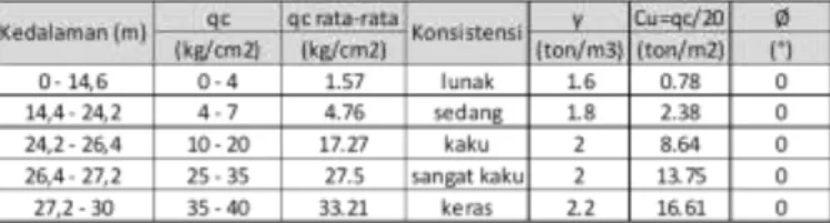
Based on the results of the SPT testing, to be able to determine the soil profile, the data is correlated with the Terzaghi and Peck 1967 tables, empirical formulas according to Stroud (1974), and empirical formulas according to Hara et.
Al. (1971). Based on these correlations, the following land parameters can be taken :
Tabel 4.1 Soil Layer Profile Based on SPT Test
Cu values obtained from the approach using the table N-SPT Relations Against the Consistency of Clay Soils interpolated with N-SPT values obtained from boring results, in this design the value of Cu = KN with the value K = 0.5 is
91 used because the resulting Cu value is the most critical value among the other approach approaches, chosen is the most critical for security reasons. provide the SPT Test
To determine the content weight γ of the soil also use using the table N-SPT Relations Against the Consistency of Clay Soils. Therefore the soil profile can be divided according to the consistency of clay.
The soil at this location is considered saturated clay so that the inner shear angle (𝜙) = 0, is considered saturated because it conditions the soil in the most critical condition to be able to make a safer design.
Based on the results of the sonder test, to be able to determine the soil profile, a table of interpretation of the results of land investigation is used using a sondir on the civil engineering book page 132. Based on these correlations, the planning parameters are as follows :
Tabel 4.2 Profile Of Soil Layer Based on CPT Test 4.4 Stratigraphy
Based on the results of soil classification, the soil stratigraphy is divided into several layers based on the testing points of boring and sondir as a reference of the depth of the slope, so that the most conservative values are taken :
1) Layer 1 : γ = 1,6 t/m3 Cu = 0,35 t/m2
𝜙 = 0ᵒ
2) Layer 2 : γ = 1,8 t/m3 Cu = 2,38 t/m2 𝜙 = 0ᵒ 3) Layer 3 : γ = 2 t/m3
Cu = 5,38 t/m2 𝜙 = 0ᵒ
92 4) Layer 4 : γ = 2 t/m3
Cu =11,50 t/m2 𝜙 = 0ᵒ
5) Layer 5 : γ = 2,2 t/m3 Cu = 16,61 t/m2 𝜙 = 0ᵒ
Picture 4.1 Stratigraphy 4.5 C Residual Determination
From observations in the field, the road cracking point was seen 4.8 meters from the edge of the river slope. Because the slopes experience symptoms of the landslide, so the value of shear strength at a depth of the soil approaching the landslide needs to be corrected to Cu Residual.
Residual Cu is determined by estimating the safety value of SF ± 1 by assuming that the landslide is approaching in the field so that the slip plane is set at that depth, in this design the collapse field reaches ± 8 meters depth.
93 So that the soil profile data reaches a depth of ± 8 meters using Cu residual with a value of 0.35 tons / m2. The soil at ± 8 meter depth is considered to be soft soil with a friction angle of 0 because it is considered to be saturated clay.
4.6 Parameter Desain
Soil design parameters can be seen in the following table:
Tabel 4.3 Profile Of Soil Layer With Correction 4.7 Construction Analysis Of Plaster
Picture 4.2 Cross Section Structure Of The Soil Layer
94 Calculation Of Soil Pressure Coefficient
In calculating the soil pressure coefficient using the theory of Rankine, as follows :
Ka = ( ) = ( ) = 1 Kp = ( ) = ( ) = 1
Calculation Of Effective Ground Stress
Active
Z = 0 m
1 – 2 . C1 = (1,6 . 0 + 2,13). 1 – 2 . 0,35
Z = 3 m
1 – 2 . C1 . √
= (1,6 . 3 + 2,13). 1 – 2 . 0,35 √
Z = 14,6 m
– 2 . C1 . √
= – 2 . 0,35. √
– 2 . C2 . √ = – 2 . 2,38 √
Z = 14,6 + D
– 2 . C2 . √ – 2 . 2,38. √
95
Passive
Zp = 0
σp1 = {(1,6 – 1) . 0 + 0} . 1 + 2 . 0,35 . √ = 0,7 t/m2
Zp = 11,6 m
σp2 = {(1,6 – 1) . 11,6 + 0} . 1 + 2 . 0,35 . √ = 7,66 t/m2
σp2 „= {(1,6 – 1) . 11,6 + 0} . 1 + 2 . 2,38 . √ = 11, 72 t/m2
Zp = 11,6 + D
σp3 = {(1,6 – 1) . 11,6 + (1,8 – 1) . D} . 1 + 2 . 2,38 . √ = 11,72 + 0,8 D
Picture 4.3 Active and Passive Soil Pressure Diagrams Calculation Of Soil Pressure
Pa1 = . H
96 = 1,43. 3
= 4,29 ton Pa2 = . H . ( = . 3 . ( = 6,15 ton
Pa3 = . H = 5,53 . 11,6 = 64,148 ton Pp = . H = 2,59 . D = 2,59D ton Search For D and F Moment Arm (Against F)
H1 = 3 - 1 = 0,5 m H2 = 3 - 1 = 1 m
H3 = 11,6+3 - 1 = 7,8 m
H4 = D + 11,6 + 3 - 1 = 13,6 + 0,5D 𝝨M = 0
(Pa1.H1) + (Pa2.H2) + (Pa3.H3) - (Pp.H4) = 0
(4,29 . 0,5) + (6,15 . 1) + (64,15 . 7,8) – 2,59D(13,6+0,5D) = 0 2,145 + 6,15 + 500,37 – 35,224D – 1,295D2 = 0
1,295D2 + 35,224D – 508,665 = 0
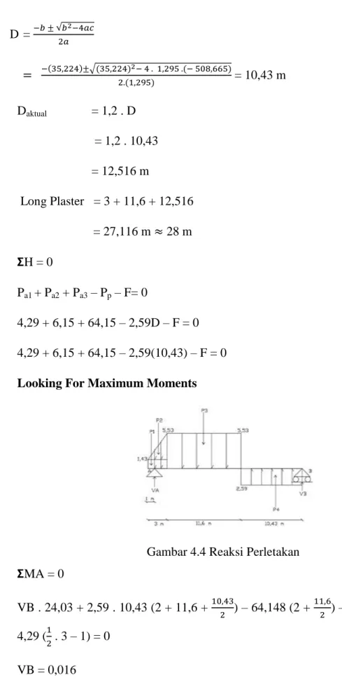
97 D = √
√
= 10,43 m
Daktual = 1,2 . D
= 1,2 . 10,43 = 12,516 m
Long Plaster = 3 + 11,6 + 12,516 = 27,116 m 28 m 𝝨H = 0
Pa1 + Pa2 + Pa3 – Pp – F= 0
4,29 + 6,15 + 64,15 – 2,59D – F = 0 4,29 + 6,15 + 64,15 – 2,59(10,43) – F = 0 Looking For Maximum Moments
Gambar 4.4 Reaksi Perletakan 𝝨MA = 0
VB . 24,03 + 2,59 . 10,43 (2 + 11,6 + ) – 64,148 (2 + ) – 6,15 ( . 3 – 1) – 4,29 ( . 3 – 1) = 0
VB = 0,016 𝝨MB = 0
98 VA . 24,03 – 4,29 ( .3 + 11,6 + 10,43) – 6,15 ( .3 + 11,6 + 10,43) – 64,148 ( + 10,43) + 2,59 . 10,43 ( ) = 0
VA = 42,62
Mmax terletak pada 𝝨Q = 0 VA – P1 – P2 – σ . X = 0 X =
=
= 5,82 m
𝝨Mmax = (Pa1 ( . 3+X) + (Pa2 ( 3+X) - F . 2+X + σ.X. .X)
= (4,29 ( 3+5,82)) + (6,15( 3+5,82)) –(42,62 (2+5,82)) + (5,53 . 5,82 . . 5,82)
= - 166,283 tm Profiling of Plaster
The maximum moment is known Mmax = 166,283 tm = 16628300 kg.cm
Voltage of bending permit BJ 37 ̅b = 2400 kg/cm2, then obtained :
w =
̅
w =
= 6928,46 cm3
Then from the box shape profile table available in the Civil Engineering book, FSP VIL profiles are used with w = 8700 cm3 > 6928,46 cm3.
99 Picture 4.5 FSP VIL Profile Box Shape
Recordings Calculation F = As . ̅b 47600 = . d2. 2400 d2 =
d = 5,03 cm
Picture 4.6 Recording
Mmax = . F . B2 = . 47,6 . 22
= 23,8 tm = 2380000 kg.cm w =
̅
=
= 991,67 cm3 Steel Pile
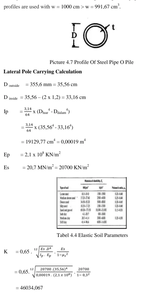
100 Steel poles are available in the Civil Engineering book page 301. Steel pipe O profiles are used with w = 1000 cm > w = 991,67 cm3.
Picture 4.7 Profile Of Steel Pipe O Pile Lateral Pole Carrying Calculation
D outside = 355,6 mm = 35,56 cm D inside = 35,56 – (2 x 1,2) = 33,16 cm Ip =
x (Dluar4-Ddalam4) =
x (35,564-33,164) = 19129,77 cm4 = 0,00019 m4 Ep = 2,1 x 10⁸ KN/m2
Es = 20,7 MN/m2 = 20700 KN/m2
Tabel 4.4 Elastic Soil Parameters K = 0,65 . √ .
= 0,65. √
.
= 46034,067
101 R = √
= √
= 0,965 Zmax = =
= 29,01
Picture 4.8 Chart A‟x ,B‟x , A‟m, B‟m
X = 0,5% . H X =
. 300 = 1,5 cm X =
=
Qg = 0,015 x
= 477,08 KN
From the graph A‟m maks = 0,5 w =
=
Z = 0 m Z = 0
29,01 = 0 A‟x = 1,3
102 = 0,001 m3
̅b = 2400 kg/cm2 = 240000 KN/m2 The moment is carried by the pole : M = w x ̅b = 0,001 x 240000 = 240 KN.m
M = A‟m x Qg x R 240 = 0,5 x Qg x 0,965 Qg =
= 497,41 KN > 477,08 KN Qg = 477,08 KN
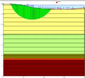
4.8 Slope Stability Analysis After Being Reinforced With The 2012 Geostudio Program
In this analysis traffic loads, loads outside the road, and road pavement are included in the GeoStudio program. The load on road and road construction is 21.3 kN / m2 while the off-road load is 10 kN / m2. In this analysis, percutaneous will be added using steel plaster. The results of the previous analysis, namely the initial conditions obtained SFcritical = 0.959 according to conditions in the field.
After being given percutaneous with steel plaster and calcined, it was obtained SFcritical = 1,835. The safety factor that was obtained was not SF ≥ 1.5 based on Pd. T 09-2005-B is taking into account high-risk factors. From the results of this analysis, it can be concluded that the slope is safe after being given steel plaster reinforcement with SF = 1,835 ≥ 1,5.
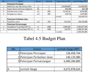
103 Picture 4.9 Slope Landscaping Results After Being Given Strengthening 4.9 Cost Budget Calculation
Tabel 4.5 Budget Plan
Tabel 4.6 Recapitulation Of The Budget plan 5. Closing
5.1 Conclusion
Based on the results of the plasterboard construction design as an alternative to handling landslides in the North Kuin Street section, North
104 Kuin Village, North Banjarmasin District, South Kalimantan Province, then the following conclusions can be taken:
1. Plaster construction that is safe and meets technical requirements is as follows:
a. In the calculation of plasterboard construction design as an avalanche handling on the North Kuin Road section using a plastered anchor calculation analysis with steel piles.
b. In calculating the D depth of design, it is found that the penetration of the plasterboard is D = 10.43 m, so that the overall plaster length is 28 m.
c. The maximum moment obtained from the calculation is 166,283 t.m, then the box-shaped steel sheet is used with an opposing moment of 8700 cm3 and steel piles with a diameter of 35.56 cm so that the construction of the plaster is declared safe.
d. Based on the results of the analysis of slope stability with the GeoStudio 2012 application we obtained a safety figure of 1.835 > 1.5.
2. The results of the design drawing plan / DED (Detail Engineering Design) are in the attachment.
3. The results of the cost recapitulation for plaster design amounted to Rp.7,340,166,486, - for 40 m long plaster length from STA 0 + 000 to STA 0 + 040.
5.2 Suggestion
From the design it is suggested several things as follows :
1. It is recommended that the data used must be more complete in accordance with the conditions and depth of the soil, so that more detailed and efficient planning results will be obtained,
2. The calculation of the maximum moment on the plaster must be calculated carefully, because it affects the determination of the dimensions of the plaster.
3. It is better to measure slope height more carefully because it is very influential in the calculation to determine the design length of the plaster.
105 DAFTAR PUSTAKA
Das, Braja M. 2013. Mekanika Tanah Jilid I (Prinsip-prinsip Rekayasa Geoteknis). Jakarta: Erlangga.
Hardiyatmo, Hary Christady. 2014. Analisis dan Perancangan Fondasi I edisi ketiga. Yogyakarta: Gadjah Mada University Press.
Hertiany, Isti Radhista dan Adwiyah Asyifa . 2014. PERENCANAAN KONSTRUKSI SHEET PILE WALL SEBAGAI ALTERNATIF PENGGANTI GRAVITY WALL (Studi Kasus Proyek Sindu Kusuma Edupark, Yogyakarta). Yogyakarta : FST-Universitas Teknologi Yogyakarta.
http://autoshare88.blogspot.com/2012/02/penerapan-turap-sebagai-dinding- penahan.html. Diakses 31 Oktober 2018.
http://tosimasipil.blogspot.com/2014/02/analisis-turap.html. Diakses 31 Oktober 2018.
Supriyanto, Maradona. 2015. PERENCANAAN PERKUATAN DINDING PENAHAN PADA BANTARAN SUNGAI KONTO DI KECAMATAN PUJON. Malang : Universitas Tribhuwana Tunggadewi.
Syafruddin. 2004. DESAIN DINDING PENAHAN TANAH (RETAINING WALLS) DI TANAH RAWA PADA PROYEK JALAN. Banjarmasin : Universitas Lambung Mangkurat.
Umum, Kementrian Pekerjaan. 2013. “Pedoman Analisis Harga Satuan Bidang Pekerjaan Umum.” PERMEN PU RI no.11/PRT/M/2013.
Zakaria, Zufialdi. 2009. Analisis Kestabilan Lereng Tanah. Jatinangor:
Universitas Padjadjaran.
106 This page is intentionally left blank