Introduction Multimeters
Instructions and Basics
Cautions when using a Multimeter
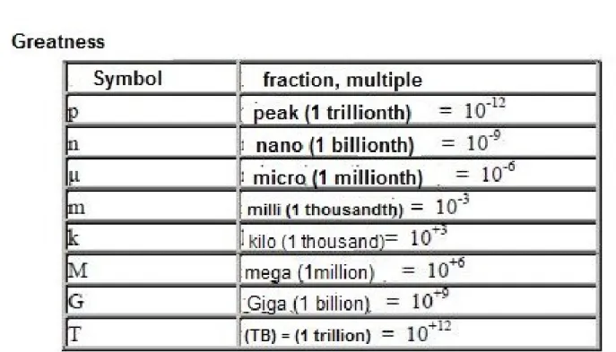
Table with symbols and quantities of electricity Introduction to electronic injection
Main components NTC
Diode
Voltage regulator Electrolytic capacitor Drive
Transistor
Eprom - ROM memory RAM memory
PAL decoder EEprom - 95160 Processor
Crystal or Clock
Common defects (cause and effect) Cause
It
is made Solution
Electrical Resistance Resistor Test
Resistance calculation table for a resistor:
SMD Resistor
Electronic injection modules: Features, defects most common and repair tips
Magneti Marelli 4SF - Fiat Magneti Marelli 4AFB - Fiat Magneti Marelli 49FB - Fiat Magneti Marelli G7.11 - Fiat
[>Ecu Modules Repair Ebook PDF<]
Magneti Marelli 1G7 - Fiat Magneti Marelli G7 - Fiat Magneti Marelli 1ABG - Fiat 5NF - Fiat
Motronic 1.7 - Fiat 7.9.6 - Fiat and GM
HSFI or MT27E - Fiat and GM Motronic 1.5.1 - GM
Multec 700 - GM Motronic 1.5.4 - GM Multec MPFI EMS –GM Multec H VHC - GM
EEC V - ANIL AND ENIO - FORD EEC IV - FORD
Magneti Marelli 4CFR - Ford Magneti Marelli 4AFR - Ford Magneti Marelli 4LV - VW Magneti Marelli 1 AVB - VW Magneti Marelli 4SV
Temic 1.74 1 AVP - VW MP
9.0 - VW 1AVI - VW 4AVP - VW 4BV - VW 7.5.20 –VW Bosch 3.8.3
Bosch LE - JETRONIC Bosch ME 7.4.4 Petrol Magneti Marelli 5NP 02 Magneti Marelli 6LP1 Magneti Marelli 6LPb Magneti Marelli 5NP 01
Bosch MP7.2
Siemens Sirius 3134 Siemens - Sirius 32
Mercedes Class A 160 and 190 - VDO MSM
Introduction
Over time and the need to improve everything, the number of electronic components in automobiles comes
progressively increasing in order to improve from fuel efficiency to driver comfort.
As a result, more and more mechanical parts are transformed into electronic components.
Today the vast majority of automobiles use the electronic injection and are constantly increasing as well as the need for qualified technicians to ensure its smooth operation.
Therefore, investing in material and knowledge is no longer a matter of staying ahead of the competition, it's almost an obligation.
Next, you will learn more about injection modules electronics: the main characteristics, identify the main components, their functions, the most defects common, and more.
Multimeters
One of the main and essential tools for anyone
works with electrical and automotive electronics is the multimeter, know all the functions and know how to use it correct way can help a lot when diagnosing
failure or make a repair.
[>Ecu Modules Repair Ebook PDF<]
Instructions and Basics
There are basically two types of multimeters, the analog
and digital, but we go from the emphasis to digital, because it offers greater ease when making a measurement.
Through a display we can easily see the greatness measured without the need to multiply and
readings on complicated scales as in the case of analog multimeters.
We use the digital multimeter for various purposes, the most common is to perform some measures, such as example:
•Measure electrical voltage (volts - V).
•Measure electrical current (amps - A).
•Measure electrical resistance (0hms – Ω).
In addition to these examples, depending on the model, it can have options for other measures such as: frequency,
temperature, semiconductors (for example a diode), transistors, capacitance, continuity (with audible signal), etc.
Regardless of the magnitude, in digital multimeters the value of the selected scale already shows the maximum value to be measured. See below for an example of the most
common found for each scale:
•Resistance scales : 200Ω, 2000Ω or 2kΩ, 20kΩ, 200kΩ, 2MΩ or 2000kΩ
•DC voltage ranges: 200mV, 2V, 20V, 1000V or 200Mv, 2V, 20V, 1000V or 1kV.
•Alternating voltage scales: 200V, 750V or 200V, 750V.
•DC scales: 200uA, 2000uA or
•Alternating current scales : 2A, 10A.
The selection of the scales can usually be done through a rotary key, buttons or even no key
any, are the case of the digital multimeter the auto function range (auto scale), it selects the scale and the magnitude automatically.
There are also some models of multimeters with auto range which has only one voltage scale, one for
current and one for resistance, it is not necessary to worry about selecting a specific scale to measure a certain voltage value.
An important detail when handling a digital multimeter is to know the correct scale for the measurement you want of. Below are some examples of quantities with
their names on the scales:
•Continuous voltage : VCC, DCV, VDC or V with a dashed line and another continuous line over it.
•AC voltage: VCA, ACV, VAC or V together with the symbol - on it.
•Direct current: DCA, ADC or A with one line dashed and another continuous on it.
•Alternating current: ACA or A together with the symbol - about it.
•Resistance: 0hms, Ω.
Cautions when using a Multimeter
The use of a multimeter must be done with sufficient attention and never touch your fingers with any
test leads during measurement to avoid
an incorrect reading, or depending on what is measuring, you risk an electric coke. ever read the multimeter's manual before using.
[>Ecu Modules Repair Ebook PDF<]
Most digital multimeters have four terminals for connecting the test leads. Usually one is in common (COM) and the others are for each
specific measurement (voltage, resistance and current).
Terminals always indicate which scales they are must be used.
See the following example of how they have a multimeter with auto range function.
1 Terminal indicated with 10AMAX - We must connect the red test tipfor measuring current
continuous or alternating pressure greater than 200mA.
Note: Some digital multimeters do not have the option to measure alternating current. Before do the test make sure the multimeter has this option.
2 Terminal indicated with µA / mA - We must connect the red test tipfor measuring
amperage (in micro or milli amps). At the maximum of 200mA.
3 Common terminal, COM - We must connect always the black test tip.
4 Terminal indicated with V / Ohms / F / Hz - We must connect the red test lead to measure
voltage (continuous or alternating), frequency, diode, resistance, continuity, capacitance and hFE.
[>Ecu Modules Repair Ebook PDF<]
Table with symbols and quantities of electricity:
Introduction to electronic injection
Thanks to the electronic fuel injection system,
manufacturers have managed to greatly improve performance engine efficiency, fuel efficiency and engine comfort
driver.
The electronic injection system uses several sensors and
actuators to provide the engine with the correct mix of air and fuel for specific operating conditions.
All of these sensors and actuators are monitored and controlled through a management module
electronic.
So it's very important to know how the “brain”
of the system works to have from an accurate diagnosis until you do your own repair.
Main components NTC
If it is a protection device, it is usually
connected between the power input (positive and negative).
In case of an overload is due to a short circuit
or because of a reversal of the polarity of the battery,
this component heats up and closes a short circuit between positive and negative inputs, breaking the trails of
board at the module entrance, protecting the components more sensitive.
[>Ecu Modules Repair Ebook PDF<]
Diode
In the case of Rectifier Diodes, when a
over voltage, that is, the “voltage” is exceeded, the
component conducts the current in the direction of blocking the diode, producing the same effect as the previous example, the disruption of entry trails.
A diode has the characteristic of allowing the passage of electrical current in one direction and block in the other, to avoid a short circuit.
Voltage regulator
The electronic circuit of the exchanges normally works
with 5 volts, therefore, the regulator is one of the components responsible for the proper functioning of the modules and injection system.
[>Ecu Modules Repair Ebook PDF<]
Electrolytic capacitor
The capacitor is used to filter the input voltage before and after the voltage regulator. It consists
internally by two dielectrics and an acidic substance, over time, this substance may leak
acid causing short circuits and plate corrosion.
These types of capacitors are used in filtering power supplies, low-voltage oscillating circuits
frequency, low frequency signal coupling and timer circuits.
There are two types of electronic capacitors: Those that have the metallic body (the most common) and those with the body in epoxy, similar to diodes. Some show the
characteristics indicated by a letter (working voltage) and a number (value in MF): ex: 22/16.
To test electrolytic capacitors it is necessary to
firstly, to know its value in Microfarade to be able select the correct measurement scale.
Scale values in microfarade Scale
Microfarade (µF)
X1 or X10---From 330 to 10,000 X1K From 0.05 to 220 Also note that the electrolytic capacitor has
polarity (+ and -). It is also found in the body of the capacitor the working voltage value.
[>Ecu Modules Repair Ebook PDF<]
Drive
They are the components responsible for triggering the injector nozzles, ignition coil, and solenoids through of a low power electrical signal.
To access internal functions and features, check in the Datasheet.
A coil drive normally short-circuits when the coil is defective.
The drive consists of a power transistor that can be be mounted individually or in Integrated Circuit with several internal components.
Transistor
Low power transistors are used for the
switching of drives and for signal communication processed digital.
The function of the transistor is to switch electrical circuits from high power through a low power.
[>Ecu Modules Repair Ebook PDF<]
It works similar to a relay, but much more effectively.
Among other functions, it is also used mainly as an output drive to drive injector nozzles, coils etc.
Eprom - ROM memory
It is found in models of
type DIP, PLCC, PSOP or integrated internally in the processor in Hybrid ECUs.
[>Ecu Modules Repair Ebook PDF<]
They carry the parameter information to the engine operation: advance, injection time, temperature etc.
Programming can be done only by changing the chip or with the use of special equipment.
RAM memory
It is the volatile memory, where the auto parameters are injection system adaptations.
PAL decoder
Transforms analog signals into digital signals and organizes all this information for the processor.
It is possible to find modules with a single component, or with several, with unique functions (rotation, detonation, etc.) which is the case with some Bosch power stations.
EEprom - 95160
Serial Eprom with SOIC8 package are
information such as immobilizer code is stored, engine, airbag, body module etc.
In some cases they can be reprogrammed via scanner or with the help of programmers.
[>Ecu Modules Repair Ebook PDF<]
Processor
As with a conventional computer, the processor is the injection module heart.
Contains internal software with working parameters of the system.
Crystal or Clock
In every crystal, the material it is made of has a unique characteristic of having a natural frequency.
The processor uses this frequency to determine the time in which all the routines will be performed job.
Therefore, it is observed that the more modern the central the higher the clock frequency (crystal) of the
processor.
[>Ecu Modules Repair Ebook PDF<]
Common defects (cause and effect)
Cause
Several factors can cause poor contact in welds terminals, components or broken trails.
For example:
•Time action;
•Oxidation;
•External short circuit;
•Over load, due to lack of grounding of the external components.
It is made
•Some ground or power will be missing sensors;
•Actuators will not work;
•Central does not work.
Solution
•Check the cause of the defect;
•Redo the weld or rebuild the track with wire cloaked.
Electrical Resistance
Resistors are electronic components that have the
function hinders the passage of electric current through the your stuff. This difficulty is called resistance
electrical.
Resistor Testing
Unit...OhmΩ
Kilo Ohm ... kΩ = 103 Mega OHM ... MΩ = 106
There are two types of resistors, fixed and variable:
Fixed: They are resistors in which their electrical resistance does not can be changed (features two terminals.)
Variables: Are those resistors in which their resistance electrical can through an axis or stroke (rheostat,
Potentiometer).
[>Ecu Modules Repair Ebook PDF<]
A color code is used to identify the value of a
resistor, where each color and its position in the body of the resistors represent a value or a multiplicative factor.
Resistance calculation table for
one resistor:
SMD resistor
SMD resistors are at least 1/3 the size of
conventional resistors. Most are welded on the side of
under the board by the side of the tracks, occupying much less space.
They are resistors to be mounted on the surface (SM in English Surface Mounting). Your reference has a
encoding which can be three or four digits. The most used in electronic equipment are the resistors
SMD with three.
In resistors with 3 characters, the first two
numbers indicate the most important digits of the resistor, the last digit indicates the multiplication factor, in this case 100, so in the case of the resistor in the example above one has a resistance of 1000 ohms.
[>Ecu Modules Repair Ebook PDF<]
4
Electronic injection modules:
Features, more defects tips and repair tips
Magneti Marelli 4SF - Fiat
Vehicles: Fiat with 1.0, 1.4 and 1.8 engines, with electronic accelerator.
5 3
2
1 1
0 6 7 8 9
Main components:
1 5V regulator;
2 Nozzle / Fan / Main relay;
3 Electronic accelerator;
4 Capacitor;
5 Coil 1 and 4;
6 Knock sensor;
7 Processor - ST -10;
8 Crystal - 10 MHz;
9 Lambda probe;
10 coil 2 and 3.
Technical specifications Special features
•The letter '' S '' after 4 means that the system has electronic accelerator;
•It is considered a hybrid plant, because it has the injection and immobilizer maps on the processor.
•Injection and immobilizer maps can only be
accessed with ST10 programmer, and through Boot.
[>Ecu Modules Repair Ebook PDF<]
Common defects
•Failure in the DC motor drive, causing failure in the acceleration.
•Processor software failure. Many power plants may malfunction due to
defect in the processor software (oscillation of idling, acceleration failure, etc.).
exchange the software for another (tele-loading).
Ignition drive - VB 025 MSP
Between point 9 of the component and the processor, there is a current limiting resistor of 1Kohms.
Lambda probe heating control - VDN 7N V04
This component controls the negative, by PWM, varying the
[>Ecu Modules Repair Ebook PDF<]
applied voltage.
Mult Drive L9131 - 36 Pins
Controls 10 components of this ECU.
Mult Drive L9131 - 36 Pins
Controls 10 components of this ECU.
Drive L9132 - 36 Pins
Drive L9132 – 36 Pinos
Butterfly motor control drive - TLE 6209 R
Controls the opening and closing of the throttle acceleration, by PWM.
Pins 1 - 10 - 11 - 20 (Ground) are connected to the
metal at the bottom of the component, where it should be soldered to the circuit board.This ensures that the component don't overheat.
[>Ecu Modules Repair Ebook PDF<]
Detonation interface - AA205AC1 - H992N0430 - ST - 20 Pins
The detonation circuit has no capacitors at the input, only 2Kohms series resistors.
[>Ecu Modules Repair Ebook PDF<]
Magneti Marelli 4AFB - Fiat
Vehicles: Palio 1.0 8V Flex.
Main components
1 Fan 1 and 2 / Main relay;
2 Lambda probe;
3 Cold start;
4 Coil 2 and 4;
5 Coil 1 and 4;
6 Nozzles / Stepper motor / Canister;
7 Soic 95160 / Code;
8 Processor - ST10;
9 Can network; (Note: Cars with BC).
10 Capacitor.
Technical specifications Special features
•There is 4AFB with panel, box or Body Computer.
4AFB - Gasoline is not interchangeable with flex.
Common defects
•Oxidation on the plate, electro fan and cold start.
Note: AFR regulation is used, 9
for alcohol and 13 for gasoline. The cold start would only function if the AFR is below 10.5 and the temperature water and air are below 16 ° C.
Immobilizer, use the decode.
Processor: ST10.
RPM signal: Phonic.
Coil signal: Digital.
[>Ecu Modules Repair Ebook PDF<]
Magneti Marelli 49FB - Fiat
Main components
1 Multi functions - L9104 - 5V regulator - Relay main - Relay A / C;
2 Memory Rom - 29F200 AB;
3 Processor - Motorola - ZC 439507 MF T 20;
4.MAR 9109 PD Multi Drive - 20 pins - Injectors - Canister - Stepper motor - V1 and V2 fan;
5 Drive ignition coil 1 and 4 - VB025;
6 Ignition coil drive 2 and 3 - VB025;
7 Detonation interface - L9119;
8 Soic 8 - 95040 - Immobilizer;
9 Blasting interface – AA205AC.
Common defects
•Oxidation of the board causing fan failure or burning the drive that controls the fan;
•Burn the drive that controls the nozzle outlet.
Ignition coil drive – VB025
MAR 9109 PD multi drive - 20 pins - Injectors - Canister - Stepper motor - Fan V1 and V2.
[>Ecu Modules Repair Ebook PDF<]
Multi functions - L9104 - Regulator 5V- Main relay - Relay BC
Detonating magneti – L9119
Magneti Marelli G7.11 – Fiat
List of components
•Processor - Motorola MC68HCP11A1 - 52 pins;
•RAM memory - MHS MM3 65162S0129;
•PAL-ST B22AF627 decoder;
•BU 931 and BU 941 - Ignition Coils;
•L4947R - Voltage regulator 5 volts;
•CA3262 AE - Quadruple mult drive.
[>Ecu Modules Repair Ebook PDF<]
BU 931 or BU 941 - Ignition Coils
Coil A - Cylinder 1 and 4
The coil A drive is driven by the PNP transistor of low power shown below, among them is the transistor current limiter of 100 Ohms.
Coil B - Cylinder 2 and 3
The drive of coil B is driven by the PNP transistor of low power shown below, among them is the resistor current limiter of 100 Ohms.
[>Ecu Modules Repair Ebook PDF<]
The injector drive is driven by the low-voltage PNP transistor power shown below.
CA 3262 AE - Quadruple mult drive This component works similarly to
NPN transistors, that is, the input (trip) is made by positive 5 volts and the output is negative.
Drive A - Diagnose - Solenoid Relay 2 and Solenoid Valve 1
Drive B - Fuel pump relay - Injection light
Note: The pump relay and the fault lamp
[>Ecu Modules Repair Ebook PDF<]
have a diode in series, as shown in the following image.
Processor - Motorola MC68HCP11A1
Magneti Marelli 1G7 - Fiat
Vehicles: Canopy, Fiorino and Uno, 1.0 and 1.5 mpi.
6 5 4
7 3
8 2
9 1
1
0 1 1 1
1 2 3
Main components 1 Stepper motor;
2 Coil 2;
3 Coil 1;
4 Canister;
5 Double relay;
6 Capacitor;
7 Nozzle drive (single point); Note: You will not have the drives 8 and 9.
8 Nozzle 2 and 3;
9 Nozzle 1 and 4;
10 5V regulator;
11 Capacitor;
[>Ecu Modules Repair Ebook PDF<]
12 Processor;
13 Eprom memory.
Technical specifications Special features
•The immobilizer is on the processor.
•The immobilizer is optional.
Common defects
•The 96/97 system came out with a processor defect.
When successive failures occur, the software of the processor blocks the stepper motor, causing
idle oscillation. This failure will only be
repaired when the reset procedure is performed.
processor, using the tool chip.
Note: Nozzle drive - Commercial - IRF 34.
Drive relay A
Activate side A of the double relay, by pin 4 of the ECU.
Caution: Between pin 4 of the ECU and the relay drive A has a diode.
Micro transistor that drives the A relay drive
Drive Coils ignition
Drive CA 3262 AE - Relay A / C - Relay B - Injection light This component works similarly to
NPN transistors, that is, the input (trip) is made by positive 5 volts and the output is negative.
[>Ecu Modules Repair Ebook PDF<]
2 3
1 0 9
4 7
Magneti Marelli G7 - Fiat
Vehicles: Uno / Premium Families / Tempra 8V and 16V.
1
5 6 8
1 Main Components 2 Varistor;
3 5V regulator;
4 Nozzle drive;
5 Processor;
6 Eprom;
7 Rom memory;
2 Auxiliary processor - MC68HC11;
3 Coil drive 1;
4 Coil drive 2;
Technical specifications Rotation Signal: Phonic 60-2
Transformation: Tempra 8V to 16V just change the file One 1.0 gas. For 1.5 gas. just change the
archive
OBS: 1 - When exchanging these exchanges
pay attention if the car has air conditioning and sensor detonation.
2- It is not advisable to exchange
gasoline for alcohol because the starting system is original cold will not work.
Eprom: 27C256 - Uno e Elba 1.5 and 1.6 from 92 to 94 27C512 - Family One and Tempra from 94 onwards Common defects:
- Varistor firing: check for possible alternator or short circuit in the harness.
How to solve - Change the varistor.
- Disruption of the sensors' TERRA track (follow pin 31 of the nozzle).
How to solve - resold the track.
- Memory eprom or Ram accused by the scanner.
How to solve it - Change the auxiliary processor (photo 8)
- Electrolytic capacitor bursts and corrodes the tracks below his.
How to solve- Change the capacitor and rebuild the tracks.
Ignition coil drive - BU 931 or BU 941
[>Ecu Modules Repair Ebook PDF<]
The coil A drive is driven by the PNP transistor of low power shown below, among them is the resistor current limiter of 100 Ohms.
The coil B drive is driven by the low-voltage PNP resistor power shown below, among them is the resistor
current limiter of 100 Ohms.
Injector drive (s)
The injector drive is driven by the low-voltage PNP transistor power shown below.
L 298 N - Stepper Motor
[>Ecu Modules Repair Ebook PDF<]
L 4947 R - 5V voltage regulator
CA3262 AE - Quadruple Multi Drive This component works similarly to
NPN transistors, that is, the input (trip) is made by positive 5 volts and the output is negative.
Magneti Marelli 1ABG - Fiat
Vehicles: Palio 1.6 16V
Main components 1 DIP memory;
2 Regulator 5 volts;
3 Coil 1 and 2;
4 Protection diode;
5 Canister;
6 Nozzles;
7 Idle actuator.
[>Ecu Modules Repair Ebook PDF<]
Technical specifications Special features
•Interchangeable with 1.6 16v brava.
Common defects
•High temperature silicone oscillation and heating temperature.
Note: This car usually mechanics leave
out of point and oscillates slowly and goes out.
5
5NF - Fiat
Vehicles: Doblo 1.4 / 1.8 DBW.
4 3
2 1
Main components
1 5V regulator, electric fan;
2 Electronic accelerator, MC33;
3 Coil;
4 Coil;
5 Set of 4 protection resistors of drive nº2 (1Ω).
[>Ecu Modules Repair Ebook PDF<]
Technical specifications Common defects
•Loss of acceleration - tele-loading or motor drive of step.
Note: This 5NF ECU before tele
loading we must remove the eprom 95160 for that perform the necessary programming and boot services.
If you do not remove the eprom 95160 and execute programming ECU crashes and repair is no longer possible.
Motronic 1.7 - Fiat
Vehicles: Type 1.6 IE 8V
Main components 1 EPROM;
2 RAM memory;
3 Processor;
4 Pulse controller: Nozzle, coil and actuator drive ML;
5 Protection diode;
6 Coil 1 and 2;
7 Stepper motor and pump relay;
8 Spout;
9 5 V regulator;
10 Capacitor.
Technical specifications Special features
•Pin 1 facing the processor;
•Intel 8051 processor - 68 pins;
•Eprom 27C256 with 32 kb;
•Analog coil signal;
•Phonic RPM signal 60-2;
•Has no immobilizer;
•1 coil, rotation sensor, 1 injection nozzle.
Common Defects
•Cold solder, if it is damp or oxidized;
•Nozzle and coil oscillation;
•Check that the nozzle is original and the TPS- BUTTERFLY, the two work together;
•Locked stepper motor warms up the drive motor step and ends up burning;
•Nozzle no pulses possible defect in the processor help. This processor also controls the ignition.
•ECU for Clio Mono, Peugeot mono with Bosch 3.1 are
[>Ecu Modules Repair Ebook PDF<]
very similar, but not interchangeable.
7.9.6 - Fiat and GM
Vehicles: Vectra 2.0 Flex and Astra Flex
3
4 2
5
1
6 7 8 9
Main components 1 Coil;
2 Coil;
3 Protection diode;
4 Electronic accelerator;
5 Nozzles / Fan / Lambda Probe;
7 Processor;
8 Crystal;
9 Electronic throttle signal converter.
Technical specifications
Note: To exchange the ECU from one car to the other, just change the EPROM 95080.
When reconnecting the ECU, leave the switch on for 60 seconds to adapt.
Unlike the Marelli ECU, this Bosch ECU has a Signal “converter” of the 4 tps sensors.
HSFI or MT27E - Fiat and GM
Vehicle: Stilo and Montana 1.8
8 7 6 5
1
2 3 4
[>Ecu Modules Repair Ebook PDF<]
Main components
1. 5V regulator;
2. Soic 95040 or 95160 code;
3 Electronic accelerator;
4 Set of transistors that assist drive 3;
5 Nozzle / Pump / Main Relay / Fan / Air conditioning;
6 Coil;
7 Coil;
8 Processor.
Technical specifications Special features
•Montana ECU different from Stilo's.
Common defects
•Defect in the butterfly body, inducing to think that the error is in the ECU.
Note: The butterfly body generally ceases to
function due to failure in the SMD with the number 16250829, which is responsible for activating the body electronic butterfly.
Motronic 1.5.1 – GM
7
6
8 1
5 4
2 3
Main components
1 Pump / stepper motor;
2 Processor;
3 Auxiliary processor 4 Eprom;
5 Main relay;
6 Nozzles;
7 5V regulator;
8 Coil.
[>Ecu Modules Repair Ebook PDF<]
Technical specifications
Bosch Motronic M151 system, equips vehicles Omega to gasoline 93 to 94 (Imported).
Multi Drive 30080 3992 - 21 Pins - Low Speed Corrector - Relay A / C - Canister - Fuel pump relay - Injection light
The diode shown above is between pin 13 of the
component 30080 and pin 22 of the ECU ( Injection Light ).
When you turn the ignition has pulsed signal terminals 2:03 of amplitude of 5 volts. And at 8 and 9 there is also a signal
pulsed, of the same duration.
Multi Pin 21 Pin 300 3992 – Injectors
[>Ecu Modules Repair Ebook PDF<]
Left Multi Drive (Nozzles Only)
Mult drive Right
[>Ecu Modules Repair Ebook PDF<]
5 Volt Regulator - 3009 - 7 pins
Main relay drive - ON 588
Drive Ignition coil – 30014
Multi drive 30097 - 24 pins
Pin 14 of the Cl 30097 drives the ignition coil drive.
Between pin 14 of the 30097 and the base of the coil drive is the 100 Ohm current limiting resistor (R 500).
[>Ecu Modules Repair Ebook PDF<]
Multec 700 - GM
Vehicles: Monza, Kadett and Ipanema, from 91 to 96.
Main components 1 Injector drive;
2 16156085 - Fuel pump relay drive;
3 34993 - Stepper motor drive;
4 Delco 196 E - 16045980 - PF relay - Injection light - Flight computer - V2 fan;
5 Processor;
collector - Ascending light - A / C relay;
7 34992 - 5V regulator;
8 NTC;
9 Processor;
10 Cristal - Clock;
11 Eprom, 27C128
Technical specifications Special features
•Multec 700 exchanges are all the same, the difference is only in the mencal (Calibration Memory).
•Drive Beak - Commercial - IRF 540 or IRFZ34N.
Common defects
•Failure in the fan relay drive;
•Bad contact at the injector secondary drive terminals and pump, causing failure when moving the ECU.
Necessary to resold the terminals.
Note:
o For the injector to pulse, it is necessary to jump the
terminals D9 and D10. Doing this, passes the earthing of the D9 to D10, that is, for the injector to work is
pin D10 must be grounded.
O ECUs are the same, what changes is the month.
[>Ecu Modules Repair Ebook PDF<]
Injector drive - 3 pins
This component is a FPN NPN transistor, with
ferrite on the coupling (firing). This washer aims to eliminate electromagnetic interference.
Note: Note that the trigger has a range of 10 volts.
Secondary drive - Injector - Fuel pump
Processor
Mencal
[>Ecu Modules Repair Ebook PDF<]
Regulator 5 volts - 34992 - 15 pins
Delco 169 E 1 and 2
Delco 169 E - 1 - PF Relay - Injection light - Computer board - V2 fan - 15 pins
In this component the input (trigger) is negative and its out (out) is also negative.
- Up light - Relay A / C - 15 pins
Stepper motor drive - 34993 - 9 pins
[>Ecu Modules Repair Ebook PDF<]
Note: When the ignition is switched off, the ECU starts the engine step, that is, to test the drive just turn on and off
the ignition. And test with the oscilloscope.
Pump relay drive and Injector drive
Drive 16156085 - Fuel Pump Relay - 5 pins Input (trip) + 5 volts and output + 12 volts.
Motronic 1.5.4 – GM
Main components 1 Coils;
2 Multi fan drivers;
3 Processor;
4 Eprom;
5 5V regulator;
6 Protection diode;
7 Nozzles, Canister;
8 Stepper motor.
[>Ecu Modules Repair Ebook PDF<]
21-pin multi drive (Injectors, Canister, Fan speed 1) - 30313;
Negative shooting and negative output.
Idle Corrector Drive - 7 pins
Ignition coil drive - 30023 - 5-pin – Vectra
Coil A - Coil 2 and 3
[>Ecu Modules Repair Ebook PDF<]
Coil B - Coil 1 and 4
5V regulator and main relay drive - 30358 or 30284 - 15 pins
This component regulates the voltage 5 volts and also activates the main relay.
EGR control drive - BTS 5115 A (Blazer and S10) The component shown controls the activation of the solenoid connected in series with the EGR hose, 8V Blazer and S10 engines only.
In 16V motors, use linear EGR with drive electrical, controlled by another drive (PWM).
[>Ecu Modules Repair Ebook PDF<]
24-pin mult drive - B 58108 or TLE 4226 G
In this component, the drive is made by negative and the output is positive 5V.
Note: If one of the above diodes shorted the
controlled component will be connected directly.This happens due to the diodes having one of the terminals connected
to the ground.
Multi Drive 24-pin A (Pump relay, injection light, ignition drive)
[>Ecu Modules Repair Ebook PDF<]
24-pin Multi Drive (Fan speed 2, Relay A / C, EGR control)
Multec MPFI EMS –GM
Vehicles: Corsa 1.0 MPFI / 1.6 MPFI / Omega 2.2 MPFI / S-10 MPFI
[>Ecu Modules Repair Ebook PDF<]
Main components 1 Nozzle 1 and 4;
2 Nozzle 2 and 3;
3 Stepper motor;
4 Fault light / turning account / U8 / Canister 5 Fan 1 and 2 / EGR
6 5V regulator 7 Varistor
8 Lambda probe 9 Processor 10 Eprom
11Coil Transistor 12 PLD
Technical specifications - Rotation signal: Phonic 60-2
- Transformation: Corsa 1.0 to 1.6 just change the eprom.
Corsa for Omega 2.2 needs some adjustments in the module.
- Eprom: 27C256 32Kb
- Immobilizer: When you have it is in the HC11 processor (photo 9)
Common defects
- Varistor firing: check for possible alternator or short circuit in the harness How to solve - Change the varistor - Direct fan:
How to solve- 1- change 2-reset processor drive - Fan does not gun:
How to solve-1- check the track 2- check schedule eprom 3- Change drive.
Multec H VHC - GM
Vehicles: Montana 1.8, Celta 1.4 and Corsa 1.0.
Main components
1 Nozzles / Canister / Pump / Fan / Probe;
2 Cold start;
3 Stepper motor;
4 Capacitor;
5 Coil;
6 Coil;
7 Crystal;
8 5V regulator;
9 Soic 95040 code;
10 BGA processor.
[>Ecu Modules Repair Ebook PDF<]
Technical specifications Special features
•Interchangeable with each other as long as the file of the injection, flex ECU and gasoline ECU are not fully
interchangeable.
Common defects
•Probe does not read, SOIC corrupts the file and defects accelerated.
Note: To change the ECU from car to car, simply change the EPROM.
EEC V - ANIL AND ENIO - FORD
INDIGO
Vehicles: With 1.0 8V Rocan engine.
ENIO
Vehicles: With 1.6 8V Rocan engine.
FRONT
SEE IF
Main components 1 Protection diode;
2 Main rotation input;
3 Processor;
4 Eprom memory;
5 PLD;
6 Nozzle 1 and 2 / Stepper motor / Pump / Fan;
7 Coil (Cylinder 2 and 3);
8 Coil (Cylinder 1 and 4);
9 Soic immobilizer;
10 5V regulator;
11 Nozzle 3 and 4.
Technical specifications Special features
•With immobilizer.
Common defects:
•Failure to activate the fan.
Note: The Soic behind the sign, which contains the
immobilizer information has the original number 90510 and its similar is 25020.
[>Ecu Modules Repair Ebook PDF<]
Ignition coil drive
Multi drive - 1034SE001 - 30 pins - Injectors 3 and 4 - Revolving account
Triggering by + 5 volts and output is negative.
Multi drive - 1035SE001 - 30 pins - Canister - Injectors 1 and 2 - Fuel pump relay - Run corrector
slow - Relay A / C - V1 and V2 Cooling Trip done by +5 volts and negative output.
Lambda probe heating control drive
[>Ecu Modules Repair Ebook PDF<]
EEC IV - FORD
Vehicles: VW and Ford from 95 to 96 monoponto, with AP and CHT (AE) engines
Main components 1 Injector drive;
2 Injection diode;
3 Diagnostic control drive;
4 RAM memory;
5 Crystal / Clock;
6 ROM memory;
7 Transistor - turns on / off 5 volts;
8 Cold start drive;
9 Processor;
10 Drive fuel pump relay;
11 Stepper motor drive;
12 Quadruple Mult Drive - Canister - A / C Relay – Similar Ca 3262.
13 Transistor coil.
Technical specifications Special features
•The ECU does not control the ignition coil. This system has the TFI module.
•The quadruple multi drive can be replaced by the CA 3262, which is common in several ECUs.
Common defects
•Injector nozzle IC;
•Idle actuator CI.
Note: This car usually shortens the whip of the
nozzles and burn the CI, always check the nozzle harness and also the idle actuator. Some vehicles
may present instability in operation even
after replacing the defective component. You must reset the EC, passing something metallic on its pins. Thereby
it is possible to erase / reset the parameters things that you can't get with a scanner.
Quadruple Mult Drive - Canister - A / C Relay - (IC 17) - Similar Ca 3262 This component works similarly to NPN transistors, that is, the
input (trip) is made by positive 5 volts and the output is negative.
[>Ecu Modules Repair Ebook PDF<]
Stepper Motor Drive - (IC 123) - 15 pins
When this component has 5 volts at the input, it has 12 volts at the output.
Stepper motor drive test
When the ignition of the drive is switched on, that is, we can test them only by turning on the ignition.
Injector Drive - (IC 27B)
Triggering is done for more than 5 volts and the output is negative.
[>Ecu Modules Repair Ebook PDF<]
Mult drive (IC 6)
This drive has positive powder input (trigger) and output it is also positive.
Fuel pump drive
Cold start drive - Alcohol vehicles
[>Ecu Modules Repair Ebook PDF<]
Magneti Marelli 4CFR - Ford
Vehicles: Eco Esporte, Fiesta and Ka.
Main components
1 5 volt regulator, pump relay and thermostatic valve;
2 SOIC, code 95320;
3 Nozzles, Canister and Idle;
4 Coil 1;
5 Coil 2.
Technical specifications Special features
•Without distributor;
•Immobilizer integrated into the panel;
•Pin 01 to the right;
•4X sinusoidal RPM signal;
•Eprom on the processor;
Common defects
•Does not activate the pump relay, which is probably a defect in the bomb.
Magneti Marelli 4AFR - Ford
Vehicles: Eco Esporte, Fiesta and Ka.
Main Components
1 Thermostatic valve. 5 volt regulator, pump relay;
2 Crystal / Clock;
3 SOIC / code;
4 Beak, Canister and Slow March;
5 Coil 2;
6 Coil 1.
[>Ecu Modules Repair Ebook PDF<]
Technical specifications Special features
•Immobilizer integrated into the panel;
•Eprom on the processor;
•4x sinusoidal RPM signal;
• Pin 01 to the right;
• ST processor;
• Without distributor.
Common defects
•Does not activate the pump relay, probable drive defect the pump;
•Does not trigger or is constantly activated at fan, probable drive defect or oxidation of the board.
Magneti Marelli 4LV – VW
Main components
1. L9113 - Multi-function drive - 5V regulator - Relay main - A / C relay;
2. Soic 95080;
3 Rom memory - 29F400 BC;
4 Motorola processor - ZC439620VFT25;
5 L9110 PD - Multi drive - Canister - A / C relay - Control probe heating;
6 L9135 PD - Multi drive - Injectors - V2 Fan;
7 MC33186DH1 DC motor control drive;
8 Line 15 protection diode.
Coil
1 Coil signal amplifier transistor 1;
2 Coil signal amplifier transistor 2;
3 Set of coil signal resistors.
DC motor control drive – MC33186DH1
[>Ecu Modules Repair Ebook PDF<]
LP135 PD - Multi drive - Injectors - V2 Fan
L9110 PD - Multi drive - Canister - A / C relay - Control heating probe
Multi-function drive - 5V Regulator - Main Relay - A / C Relay
[>Ecu Modules Repair Ebook PDF<]
Magneti Marelli 1 AVB - VW
Vehicles: With AP 1.6, 1.8 and 2.0 Ml engines DE 97 to 99. And for the old model 97/98.
Main components 1 Set of nozzle drivers;
2 Stepper motor;
3 Main processor;
4 Eprom;
5 Auxiliary processor;
6 Pump;
7 Coil;
8 5V regulator;
9 5V of the map / TPS.
Technical specifications Special features
•Eprom pin 1 facing upwards;
•Has no immobilizer;
•Pump drive - CA3262;
•Coil drive - VB 027. (Pole does not use this drive).
•Stepper motor drive - L9122.
Common defects:
•Failure in the stepper motor drive - L9122;
•Failure in the coil drive - VB027;
•Pump drive failure - CA3262;
•Map power failure - Cl 33072 (8-pin tsop) Note: Some vehicles may show oscillation idle speed due to voltage instability (battery or alternator) and suspect a plant defect.
Drive CA 3262 AE - Relay A / C - Relay Fuel pump This component works similarly to
NPN transistors , that is, the input (trip) is made by positive 5 volts and the output is negative.
[>Ecu Modules Repair Ebook PDF<]
Ignition coil drive - VB 027
Stepper motor drive - L 9122
Stepper motor drive test with oscilloscope Adjust the screen to 5V x 100ms.
Magneti Marelli 4SV
Vehicles: With EA 111 1.0 8V and 16 V engines.
Main components 1 Canister;
2 Stepper motor;
3 Code / Soic 95320;
4 Coils;
5 VGA processor;
6 Crystal;
7 5V regulator;
8 Probe.
[>Ecu Modules Repair Ebook PDF<]
Technical specifications Special features
•2nd generation of Power systems, replacing the l AW system 4LV.
Common defects
•Loss of acceleration due to problems related to battery and alternator.
Note: Although this system replaces the 4LV system,
the exchanges are not interchangeable, due to the MAP sensor be different.
Temic 1.74
Vehicles: Gol 2.0 GLX from 94 to 98.
Main components
1. TLE 4216 G - Drive relay fuel pump - Coil of ignition;
2. TLE 4262 G;
3 Lambda probe heating control drive - T30;
4 Canister drive - T30;
5 Idle corrector drive - T30;
6.
7 MAP
8 ROM memory - 27C256;
9 Processor - Motorola – MC68HC11G5FN1.
Technical specifications Special features
•Has the internal map Common defects
•Fault in the idle corrector drive;
•Ignition coil drive failure;
Note: Some vehicles may show oscillation idle due to voltage instability in the
ECU power, caused by defect in the relay main.
[>Ecu Modules Repair Ebook PDF<]
TLE 4262 G - 5 Volt Regulator
TLE 4216 - Fuel pump relay drive - Coil ignition
In this component the drive is done by a positive 5V and the output is negative.
TLE 4216 G –A
TLE 4216 G – B
Injector Drive - BTS 121 A
This component is an NPN - Positive output trigger negative.
[>Ecu Modules Repair Ebook PDF<]
Transistors - T30 - Heating control of the probe - Canister - Idle corrector
1 Probe heating control;
2 Canister;
3 Idle broker.
1 AVP - VW
Vehicles: With AP 1.6, 1.8 and 2.0 MI engines from 99 onwards. And model pole old 99.
Main components 1 Canister;
2 Nozzle 4;
3 Nozzle 3;
4 Nozzle 1;
5 Nozzle 2;
6 Probe;
7 Coil;
[>Ecu Modules Repair Ebook PDF<]
1 5V / TPS regulator;
2 Capacitor;
3 Stepper motor;
4 Pump relay;
5 Auxiliary processor;
6 Eprom;
7 Main processor.
Technical specifications Special features
•Eprom pin 1 facing down;
•Has an immobilizer.
Common defects
•Failure in the stepper motor drive - L9122;
•Cold soldering on the multi-function drive - L9104 PD (20 pins tsop) due to heating.
Note: Some vehicles may show oscillation idle speed due to voltage instability (battery or alternator) and suspect a plant defect.
Drives
Ignition coil drive - VB 027
Note: The center of the Pole vehicle does not have the drive VB 027, due to the injection system using
ignition as an external power module.
[>Ecu Modules Repair Ebook PDF<]
L 9104 PD
Stepper motor drive - L 9122
Stepper motor drive test with oscilloscope Adjust screen to 5V x 100ms
Auxiliary Processor - GSCT - 38318 PG 06
.
[>Ecu Modules Repair Ebook PDF<]
MP 9.0 - VW
Vehicles: Gol 1.0 8V MI and Kombi 1.6 8V MI
FRONT
SEE IF
Main components 1 5V regulator;
2 Eprom DIP;
3 Processor;
4 Knock sensor;
5 Coil;
6 Diodes;
7 Stepper motor;
8 Nozzle mult drive;
9 Jumper for defective coil repair.
Technical specifications Special features
•There is MP9 without immobilizer, but most are with
immobilizer. The Kombi ECU is interchangeable with that of the Goal and vice versa, as long as the programming of the
EPROM, also check the knock sensor drive.
Common defects
•Coil CI and bad grounding.
Note: Burning in the coil IC, due to lack of
grounding the ECU with the battery. We should do a between the ECU housing, the battery negative and the coil housing. Check that the coil heats the
ignition module, if it gets hot we should replace it or repair it too.
B57942 or 3262 - Ignition coil, fuel and Canister.
This component works similarly to
NPN transistors, that is, the input (trip) is made by positive 5 volts and the output is negative.
[>Ecu Modules Repair Ebook PDF<]
Mult drive injectors
1AVI – VW
Vehicles: Gol 1.0 16V
Main components 1 5V regulator;
2 Main processor;
3 Eprom;
4 Auxiliary processor;
5 Coil transistor;
6 Canister;
7 Stepper motor;
8 Set of nozzle drivers.
•AVS is without immobilizer and AVI with immobilizer, a lock
on the connector is the differential between one and the other. Eliminating hangs the AVS ECU works in place of the AVI. Attention to
jumper on the ECU immobilizer.
[>Ecu Modules Repair Ebook PDF<]
Common defects
•Ci sensor map heats up;
•Ci stepper motor, without fully functioning;
•Bad contact in the eprom socket;
•Ci pump and Ci coil.
Note: The eprom 27C010, or 27C1001 can be replaced by 29F010. The main processor sends the ignition pulse signal directly to the coil in the front, we have two responsible SMD resistors
for “filtering” the signal, and at the bottom we have two more 47Ω resistors that also do this job.
Follow the track from pin 24 to the main processor.
4AVP - VW
Vehicles: Gol, Saveiro 1.6 flex
1 Probe;
2 Cold start, pump relay;
3 Crystal;
4 Processor;
5 SOIC
6 Canister nozzles, stepper motor;
7 Coil 1;
8 Coil 2;
9 Cold broken relay.
Technical specifications Special features
•Gol 1.6 8V Flex Common defects
•Ignition coil
Note: This ECU easily corrupts the
ST processor, requiring only reprogramming again. This processor is a fundamental part of functioning of the ECU.
[>Ecu Modules Repair Ebook PDF<]
4BV - VW
Vehicles: Fox and Gol 1.0 8V
Main components 1 Coils;
2 Electronic accelerator;
3 Nozzle / Fan / Canister / A / C;
4 Crystal;
5 BGA processor;
6 5V regulator;
7 Capacitor;
8 Probe.
Technical specifications Special features
•Gol 1.0 and Fox 1.6 8V Common defects
•Ignition coil and throttle body Note: This ECU easily corrupts the ST processor, requiring only reprogramming again.
7.5.20 –VW
Vehicles: Goal flex.
Main components
1 Canister probe nozzles, cold start, fan;
2 Butterfly body;
3 5V regulator.
Technical specifications Common defects
•Cold start / nozzle drive.
[>Ecu Modules Repair Ebook PDF<]
Bosch 3.8.3
Vehicles: Golf 2.0, Bora 2.0 and Gol turbo.
Main components
1 Soic 95040, Code;
2 Regulator 5 volts;
3 Probe 2;
4 Probe 1;
5 Canister;
6 Ignition complex;
7 Eprom;
8 Nozzles;
9 Idle corrector
Technical specifications Special features
•3.8.2 Passat 1.8 20V.
•3.8.3 Gol 1.0 Turbo.
5.9.2 Bora 2.0.
Common defects
•When you close a short, the trails break easily, ignition system in the complex ECU is fragile.
•Lambda probe closes short and damages the ECU.
Bosch LE - JETRONIC
Vehicles: Gol GTI 1994 Santana Executive Kadet GS
[>Ecu Modules Repair Ebook PDF<]
Main Components 1 Ignition;
2 Ignition;
3 P2IGN;
4 Visual parameters module;
5 Injector nozzles.
Technical specifications Special features
•No communication with scanner, ignition system for Santana and Versalles independent from the injection plant;
•Immobilizer does not exist in this system;
•Non-electronic analog processor;
•Analog non-electronic eprom;
•Injection light yes;
•RPM hall sign, distributor;
•Good trails;
•Cold welding, yes mainly in F and A;
Location: At the feet of the ride.
Application details: 007, VW line and 006, GM line.
Common defects: Cold solder across the plate, coil Ci burnt, open beak.
Note
1❖blink and a sudden cut, or a sudden failure. That is from electromagnetic interference, probably
spark plug, cable, coil, or any other current leak.
DO NOT rule out a problem with the EZK ignition module or even short on the whip. Another detail is the thread that goes to the coil, it has a grounding mesh, for
“FILTER” the signal to the coil but it is NOT going on next to the coil signal, this generates a short.
I❖n the air flow harness, if the vehicle is shorted, it can not get and work with a super excess and flow is without function.
T❖ he knock sensor socket is easily replaced with that of the butterfly sensor, or even the broken or very open detonation.
I❖f the Water temperature sensor is applied
wrong, the vehicle may have ignition pulsed at the nozzles, however, do not use excess fuel.
W❖eak coil, or high resistance in the cables interferes with starting the vehicle.
E❖lectrical conductivity in the cooling water or even alternator overload interferes with the vehicle after of hot.
Technical Notes
Nozzle drive: Darlington transistor, NPN (code commercial VM = TIP122 or TIR 127).
Attention, for the insulating plastic with the heat sink plate heat, and also with the fixing clamp. Test the CI with
the multimeter in DIODOS, the measurement should be between 0.4V at 0.8V. If the nozzle transistor is blown, the
resistance will be low or short-circuit between Collector and Emitter.
✓A TIP31 can also be used;
✓Remember that the CI CJ07S controls the nozzles.
If the nozzles lock open, REMOVE the plate and test the following components, LM2902A, LM2901A and LM2902B, can be replaced by an LM2902N (number
commercial).
[>Ecu Modules Repair Ebook PDF<]
Ignition drive: Due to overheating (usually the shorted coil causes this), the
solder are in bad contact. Another problem is the FET-drive ignition is burnt out due to this
overheating or short in the whip. The ignition drive
on the Marelli- G7 you can even replace this drive. Following the pin sequence A, B and C of the plate with pin 1, 2 and 3 of the new FET.
Airflow: The car has too much fuel, or it picks up
and die. When you turn the flow off and on again, the vehicle it works. Usually just resoldering points F and A
marked in the photo. Also check the electronic whip of the car.
Ignition: Below FET, there is the BC547 resistor,
(NPN) that interconnects with the ignition system, EZK. The FET ignition is isolated and commercially we can find
such as BIP109, 125B.
P1: Point where it connects with the ignition system.
It may happen to burn the resistor or the diode.
P2: Injection unit without function. When you burn the component CJ07 the unit goes out completely, nor nozzle and no coil.
[>Ecu Modules Repair Ebook PDF<]
1 Controls nozzle pulse, and influences the ignition pulse also, if you have a problem you can leave the nozzles open;
2 Responsible for the beak pulse, in case of problem beak is open too;
3 Causes excess fuel;
4 Responsible for sending signals to the air flow, causing excess fuel;
5 Component T250 has a problem and no longer reads theair flow.
Bosch ME 7.4.4 Petrol
Vehicles: Peugeot Citroën 1.6 16V and 1.4 16V family.
Main Components 1 5volts regulator;
2 TPS converter;
3 Coil 1;
4 Coil 2;
5 Nozzles, electro and Canister.
Technical specifications Special features
•Soic 95160 and psop 29f400;
•Immobilizer integrated with BSI / CSI, decodes only in gasoline vehicles. (stops the air conditioning).
To code the entire system, the Peuge