The nature of the operation of the PISTA® sand chamber dictates where it should be placed. Every feature of the PISTA® sand chamber contributes significantly to the overall performance.
TOP MOUNTED PISTA ® TURBO™ GRIT PUMP CALCULATIONS
REMOTE MOUNTED PISTA ® TURBO™ GRIT PUMP CALCULATIONS
BAR SCREEN
GRIT PUMPING
ENVIRONMENTAL CONSIDERATIONS
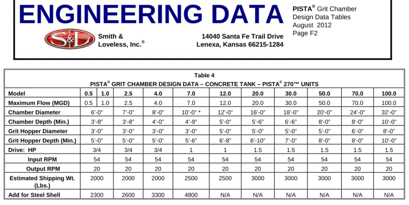
PISTA ® GRIT CHAMBER VARIABLE AND FIXED DIMENSIONS
Concrete Tank Models
PRINCIPLES OF GRIT PIPING
Flushing water: Supply of clear water into the grain pump suction line to flush the line. A flush water line connection must be installed by the contractor in the horizontal suction line before the pump shut-off valve.
ELECTRICAL SEQUENCE OF OPERATION FOR THE PISTA ® GRIT REMOVAL SYSTEM
USING THE TOP-MOUNTED PISTA ® TURBO™ GRIT PUMP
When the PISTA TURBO™ sand pump starts, a timer is provided to control the length of time the pump runs for each cycle. The PISTA TURBO™ Grit Washer (or PISTA® Grit Screw Conveyer) will start when the PISTA TURBO™.
USING THE FLOODED SUCTION REMOTE-MOUNTED PISTA ® TURBO™ GRIT PUMP
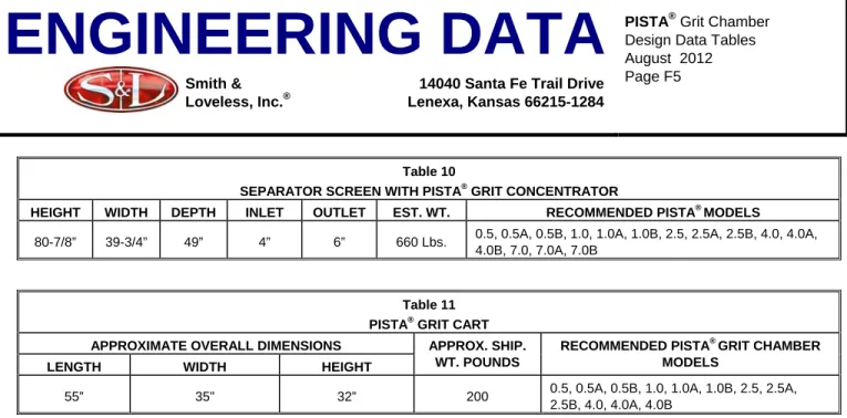
ELECTRICAL OPERATING SEQUENCE OF THE PISTA® GRIT REMOVAL SYSTEM FOR THE PISTA® GRIT REMOVAL SYSTEM. Smith & Loveless then recommends the use of the PISTA® Grit Concentrator (Table 7) and one of the four PISTA® Grit Dewatering Devices (Tables 8, 9, 10 and 11).

SPECIFICATIONS FOR
PISTA ® 360™ GRIT REMOVAL SYSTEM WITH V-FORCE BAFFLE™
GENERAL
DESIGNER NOTE: CONSULT SMITH & LOVELESS REGARDING HEAD LOSS, AS IT DIFFERS PER APPLICATION.]
CONDITIONS OF OPERATION
The PISTA® 360™ Grit Chamber will be equipped with the V-FORCE BAFFLE™, which is an integral flow control screen for both the inlet and outlet of the main chamber. The inflow chute, which conveys the liquid waste to the gravel chamber, must be of the size and shape shown on the contract drawings to ensure that gravel does not settle into the inlet chute and to allow for proper operation of the gravel chamber.
MECHANICAL DRIVE
No additional downstream flow control device is required to maintain velocity between 3.5 fps (1 m/s) at peak flow and 1.6 fps (0.5 m/s) at minimum flow with a 10:1 taper. The outlet channel must be a free flowing channel to maintain proper velocity in the chamber.
PISTA ® GRIT FLUIDIZER
First, the PISTA® Grit Fluidizer vanes must continuously pump the grit upwards into the center of the PISTA® Grit collection chamber. The PISTA® Grit Fluidizer wings must keep the grit fluidized at the suction inlet so that packing cannot occur.
GRIT STORAGE HOPPER
Second, the upward pumping action of the PISTA® Grit Fluidizer fins will improve the performance of the auger to keep organics in suspension. This will cause the heavier grain to fall downwards through the gently circulating water, and the organic matter can be more easily swept away by the currents induced by the PISTA® propeller.
STEEL CHAMBER
This gentle pumping action is to prevent grain from packing down around the pump suction tube. The fluidizing action is to prevent grain that has a sticky or greasy consistency from packing together to the point where the water created by the pump cannot break it loose.
OPTIONAL ITEM – CHECK IF REQUIRED)
PISTA ® TURBO™ GRIT PUMP – TOP MOUNTED
RECOMMENDED PUMPING OPTION #1 – CHECK IF SELECTED]
The PISTA® TURBO™ Grit Pump will be able to deliver (GPM or LPS) at a total dynamic head of (' or m). The minimum rated power of the PISTA® TURBO™ Grit Pump motor is (BHP or kW).
PISTA ® TURBO™ GRIT PUMP – REMOTE MOUNTED
ALTERNATE PUMPING OPTION #2 – CHECK IF SELECTED]
Bearing housings must be equipped with connections for lubrication and drainage of old lubricant. The motor must be equipped with lugs or heavy lifting lugs, each capable of supporting the full weight of the pump and motor.
MINIMUM REQUIREMENTS
VACUUM PRIMING SYSTEM (CHECK IF USING THE TOP MOUNTED PISTA ® TURBO™ GRIT PUMP)
To prevent excessive stoppage due to sand accumulation, no passage in the filling system through which sand must pass shall be smaller than the opening corresponding to mm). Extreme Cold Weather Package: The vacuum charging system panel will be equipped with an 800-watt heater, and heat tracing and insulation will be provided for the vacuum tubes outside the panel.
LIFTING STANCHION
Systems that use an electrode, mechanical means such as a float, or require any type of electrical or moving parts within the replenishment chamber, which may accumulate debris, short circuit, bind, or fail, will not be acceptable. The priming system will automatically provide positive lubrication of the mechanical seal every time the PISTA® TURBO™.
PLC ELECTRICAL CONTROLS FOR AUTOMATIC GRIT REMOVAL [CONTROL OPTION #1 – CHECK IF SELECTED]
Individual NEMA 4 oil tight Manual-Off-Automatic selector switches shall be provided for the pump and dewatering device drives and the rinse water solenoid control. An on-off selector switch must be provided to operate the screw-driven motor starter.
MONOCHROME 6” (150 MM) HMI
A NEMA 4 rated display unit shall be mounted through the front of the panel to provide operator input to and visual output from the microprocessor controller. An aluminum hood to shade the HMI screen from direct sunlight must be mounted on the front of the control panel.
INTERFACE OPTION #1 – CHECK IF SELECTED]
A specially pre-programmed, dedicated microprocessor control system shall be provided to control the operation of the sand removal and dewatering system and to monitor the control, environmental and alarm functions. The metal shade must cover the entire screen, protect the top and sides of the screen, and must be hinged over the screen and stowed against the front of the panel.
COLOR 10” (254 MM) HMI
The controller shall be connected to the panel display unit, motor starters, flush water, accessories and alarm functions via digital and analog input and output ports as required.
INTERFACE OPTION #2 – CHECK IF SELECTED]
The operation of the outlet clamp valve must be connected with the PLC controller and the SONIC START level sensor so that it is fully automatic. All necessary capacitors, relays, diodes etc. shall be supplied as shown in the schematic diagram.
RELAY LOGIC ELECTRICAL CONTROLS FOR AUTOMATIC GRIT REMOVAL [CONTROL OPTION #2 – CHECK IF SELECTED]
The program will be able to initiate pellet pumping cycles at adjustable intervals throughout the day. A pneumatically controlled discharge pinch valve shall be provided for installation in the vertical discharge pipe run, and the controls shall be located in the vacuum supplement control panel.
PNEUMATICALLY CONTROLLED DISCHARGE PINCH VALVE (CHECK IF USING THE TOP-MOUNTED PISTA ® TURBO™ GRIT PUMP)
To ensure continuity of operation, the manufacturer of the PISTA® grit chamber will supply these controls, as well as the full-opening, pneumatically operated pinch valve for installation on the grit discharge line, as shown on the drawings.
PRIME FAILURE ALARM (CHECK IF USING THE TOP-MOUNTED PISTA ® TURBO™
GRIT PUMP)
ELECTRICAL CONTROLS FOR MANUALLY ACTIVATED PISTA ® GRIT REMOVAL [CONTROL OPTION #3 – CHECK IF REQUIRED]
CONTROL TRANSFORMER
OPTIONAL ITEM – CHECK IF SELECTED)
PISTA ® GRIT CONCENTRATOR – 250 GPM (15.8 LPS)
CHECK IF SELECTED – TYPICALLY MODELS 0.5 TO 20.0 USE A 250 GPM (15.8 LPS) CONCENTRATOR]
PISTA ® DURALYTE ® GRIT CONCENTRATOR – 500 GPM (31.6 LPS)
CHECK IF SELECTED – TYPICALLY MODELS 30.0 THRU 100.0 USE A 500 GPM (31.6 LPS) CONCENTRATOR]
In addition, a proprietary blend of silicon carbide with a minimum thickness of ½” (13 mm) must be cast within the high wear area of the lower portion of the polyurethane cone. PISTA® DURALYTE® gravel concentrator must be supplied by the manufacturer of the PISTA® gravel chamber for installation by the contractor.
MODEL 250 PISTA ® TURBO™ GRIT WASHER WITH PARALLEL PLATE SEPARATOR (INCLUDING A 250 GPM (15.8 LPS) CONCENTRATOR) (SEE PISTA ® TURBO™ GRIT
As a minimum, 93 to 94 percent of the water pumped into the PISTA® DURALYTE® Grain Concentrator and 95 to 96 percent of the remaining organic material will flow over the top and return to the gravel chamber inlet. PISTA®. The operating range must be compatible with the total PISTA® grating removal system as described here.
DEWATERING OPTION #1 – CHECK IF SELECTED]
MODEL 250 PISTA® TURBO™ LARGE WASHER WITH PARALLEL PLATE SEPARATOR (INCLUDING A 250 GPM (15.8 LPS) CONCENTRATOR) (SEE PISTA® TURBO™ GRIT.
DESIGNER SELECT ONE OF THE FOLLOWING]
OPTION #1 – CHECK IF SELECTED]
OPTION #2 – CHECK IF SELECTED]
DESIGNER: DELETE THE FOLLOWING PARAGRAPH IF CARBON STEEL CONSTRUCTION IS SELECTED]
MODEL 500 PISTA ® TURBO™ GRIT WASHER WITH PARALLEL PLATE SEPARATOR (INCLUDING A 500 GPM (31.6 LPS) CONCENTRATOR) (SEE PISTA ® TURBO™ GRIT
DEWATERING OPTION #2 – CHECK IF SELECTED]
The clearance between the legs and the discharge outlet must be as shown on the drawing. The drive to the PISTA® TURBO™ Grit Washer shall be a belt-driven, shaft-mounted helical gear reducer.
MODEL 15 PISTA ® GRIT SCREW CONVEYOR WITH PARALLEL PLATE SEPARATOR (FOR USE WITH A 250 GPM (15.8 LPS) CONCENTRATOR)
DEWATERING OPTION #3 – CHECK IF SELECTED]
MODEL 17 PISTA ® GRIT SCREW CONVEYOR WITH PARALLEL PLATE SEPARATOR (FOR USE WITH A 500 GPM (31.6 LPS) CONCENTRATOR)
DEWATERING OPTION #4– CHECK IF SELECTED]
The machine must be mounted on a plate at the discharge end and the plate must be connected to the flanges in the trough. An expanded expanded metal mesh cover shall be provided over the hopper and choir openings.
PISTA ® GRIT SEPARATOR SCREEN (FOR USE UP TO MODEL 7.0) [DEWATERING OPTION #5 – CHECK IF SELECTED]
All carbon steel surfaces must be cleaned and coated with 6-8 mils (0.15mm-0.20mm) dry film thickness of VERSAPOX® epoxy coating, factory applied prior to shipment.
PISTA ® GRIT CONCENTRATOR SUPPORT
AUTOMATIC SPRING-LOADED LUBRICATOR
OPTIONAL ITEM WITH PISTA ® GRIT SCREW CONVEYOR– CHECK IF REQUIRED) (STANDARD FEATURE INCLUDED WITH PISTA ® TURBO™ GRIT WASHER)
CORROSION PROTECTION (FOR ITEMS OTHER THAN DEWATERING EQUIPMENT)
Finishing and final coating of paved surfaces shall be the responsibility of the purchasing contractor and shall be performed on site. The purchasing contractor shall be responsible for ensuring that the finish coat conforms to the primer specified above.
MANUFACTURING QUALITY
INSTALLATION AND OPERATING INSTRUCTIONS
MANUFACTURER’S INSURANCE
START-UP
WARRANTY
MANUFACTURED EQUIPMENT
STANDARDIZATION) [DELETE THIS LINE FROM FINAL SPEC TEXT]
The Owner has standardized the said equipment to optimize its operation, maintenance and safety programs, provide for the interchangeability of costly equipment items, reduce inventory levels for necessary spare parts and provide greater flexibility in the use of its facility.
BASE BID WITH BID SUBMITTAL) [DELETE THIS LINE FROM FINAL SPEC]
Alternative/substitute equipment can be offered as a deduction, provided all conditions of the "manufactured equipment" section are met.
PISTA ® GRIT SYSTEM CERTIFICATION AFFIDAVIT
Dimension N is the maximum head loss created by the standard size V-FORCE BAFFLE™ at the maximum flow rate rated for the unit. The maximum head loss shown is a transfer of head loss from outside the room, to the circular part of the unit.
PISTA ® 360™ GRIT REMOVAL SYSTEM GENERAL
The PISTA® 360™ gravel chamber must be equipped with a muffler at the entrance to the main chamber. PISTA® Grit Fluidizer flanges must be located within six inches (6”) (150 mm) of the height of the pump suction inlet.
PISTA ® TURBO™ GRIT PUMP – TOP-MOUNTED
The pump motor shall be vertical, solid shaft, TEFC NEMA P base, squirrel cage induction type, suitable for 3-phase, ______cycle, volt electrical current. The pump motor shall be vertical, solid shaft, TEFC NEMA P base, squirrel cage induction type, suitable for 3-phase, ____cycle, volt electrical current.
MINIMUM PUMP REQUIREMENTS
VACUUM PRIMING SYSTEM (CHECK IF USING THE TOP-MOUNTED PISTA ® TURBO™ GRIT PUMP)
COLD WEATHER PACKAGE (OPTIONAL ITEM – CHECK IF REQUIRED)
EXTREME COLD WEATHER PACKAGE (OPTIONAL ITEM – CHECK IF REQUIRED - SEE MAP IN “PISTA ® NOTES ON DESIGN” FOR AREAS WHERE THIS OPTION IS
ELECTRICAL CONTROLS FOR AUTOMATIC GRIT REMOVAL [CONTROL OPTION #1 – CHECK IF SELECTED]
PNEUMATICally CONTROLLED EXHAUST PICK VALVE (CHECK IF USING TOP MOUNTED GRIT PISTA® TURBO™ GRADE PUMP). The exhaust locking valve operation must be linked to the SONIC START cycle timer and level sensor, so that it is fully automatic.
PRIME FAILURE ALARM (CHECK IF USING THE TOP- MOUNTED PISTA ® TURBO™
ELECTRICAL CONTROLS FOR MANUALLY ACTIVATED GRIT REMOVAL [CONTROL OPTION #2 – CHECK IF REQUIRED]
CHECK IF SELECTED – TYPICALLY MODELS 0.5 THRU 20.0 USE A 250 GPM (15.8 LPS) CONCENTRATOR]
The PISTA® gravel concentrator will be constructed of Ni-Hard, with a minimum thickness of mm) in high wear areas. The PISTA® Grit Concentrator will be provided by the PISTA® Grit Chamber Manufacturer, for installation by the contractor.
MODEL 250 MOUNTED PISTA ® TURBO™ GRIT WASHER WITH PARALLEL PLATE SEPARATOR (INCLUDING A 250 GPM (15.8 LPS) CONCENTRATOR) (SEE
PISTA® TURBO™ Grit Washer shall be constructed of (304 Stainless) (316 Stainless) (Epoxy Coated Carbon) [DESIGNER: SELECT AS REQUIRED] steel, including the screw. A 1/8” (3 mm) thick expanded metal flattened cover matching the construction of the PISTA® TURBO™ Grit Washer shall be provided over the hopper and trough openings as shown on the drawings.
MODEL 17 PISTA ® GRIT SCREW CONVEYOR WITH PARALLEL PLATE SEPARATOR (FOR USE WITH A 500 GPM (31.6 LPS) CONCENTRATOR)
The hopper must be equipped with an energy dissipation area to prevent turbulence in the remainder of the hopper. The conveyor must be free with support legs to hold the conveyor at an angle of approximately 22°.
DEWATERING OPTION #4 – CHECK IF SELECTED]
The PISTA® grit screw conveyor shall be constructed of (epoxy-coated carbon) (304 stainless) (316 stainless) steel with an inlet hopper that collects the water and grit mixture. The PISTA® grit separation screen must be enclosed on two sides by 11-gauge (epoxy-coated carbon) (304 stainless) (316 stainless) steel plate.
CORROSION PROTECTION
The PISTA® Grit Screw Conveyor shall be provided with automatic spring-loaded lubricator that relies on the movement of the bearings to draw grease from the refillable reservoir to the bearing surface. Carbon steel surfaces, not otherwise protected, should be coated with a suitable non-hardening rust preventive compound.
STARTUP
Auxiliary components, such as the pellet pump, gear motor, etc., must be supplied with the original manufacturer's coating. The contractor will prepare his bid based on the specific equipment and materials specified for the purpose of determining the low bid.
BID SUBMITTAL
Specifications and drawings detail Smith & Loveless equipment and represent a minimum quality standard for equipment and materials of manufacture. Based on this equipment, the contractor will prepare his offer to determine the low offer without taking into account any replacement.
EVALUATION
TYPICAL BID FORM
ADD TO BID FORM AS APPLICABLE TO ABOVE SELECTED OPTION]
100.0A DRAWING NO. 67C157
7.0A CHART NUMBER 67A156
PISTA ® 270™ GRIT REMOVAL SYSTEM GENERAL
SPECIFICATION FOR
PISTA ® PRO-PAK™ GRIT REMOVAL SYSTEM WITH TOP-MOUNTED PISTA ® TURBO™ GRIT PUMP
PISTA ® 360™ GRIT CHAMBER WITH V-FORCE BAFFLE™ [RECOMMENDED OPTION – CHECK IF SELECTED]
The grain traveling across the bottom of the chamber must be hydraulically scoured while the propeller blades travel within 6". Propellers running with a centerline greater than 200mm from the bottom of the chamber will not be acceptable.
PISTA ® 360™ GRIT CHAMBER MODEL A
150 mm) of the gravel, passes over the moving gravel and causes hydraulic currents to lift the organic matter. The flow in the removal chamber must travel between the inlet and the outlet at least 360° (clockwise) (counter-clockwise), providing maximum travel of the liquid for effective grit removal.
ALTERNATE OPTION #1 – CHECK IF SELECTED]
To ensure efficient transport of the gravel and simultaneous lifting and discharge of the organic material, the bottom of the upper chamber covering the storage hopper shall be constructed of structural grade steel plate (epoxy coated carbon) (304 stainless) (316 stainless), free from rotation and must be flat. The inflow chute that carries the liquid waste to The PISTA® 360™ Grit Chamber must be the size and shape shown on the contract drawings to ensure that grit does not settle in the inlet channel and to ensure proper operation of the grit . chamber.
PISTA ® 270™ GRIT CHAMBER
The pellet must pass from the removal chamber through an opening in the transition plate and fall into a gravel storage bin. The outflow chute shall include a downstream flow control device, as shown on the drawings, outside of which shall be a free-flowing chute to maintain proper velocity within the chamber.
ALTERNATE OPTION #2 – CHECK IF SELECTED]
The flow in the removal chamber must travel between inlet and outlet 270° (clockwise) (counter-clockwise), providing maximum fluid movement for effective screen removal. The flow chute, which conveys the liquid waste to the PISTA® 270™ gravel chamber, must be of the size and shape shown on the contract drawings to ensure that gravel does not settle in the inlet channel and to ensure proper operation. .
PISTA ® BASE WITH INTEGRATED FIBERGLASS ENCLOSURE
The pellet traveling over the bottom of the chamber must be hydraulically sheared as the screw blades move within 6 inches. 150 mm) of the grain, passes over the moving grain and causes hydraulic currents to lift the organic matter.
DESIGNER: DELETE THE FOLLOWING 2 PARAGRAPHS IF CARBON STEEL CONSTRUCTION IS SELECTED]
DESIGNER: DELETE THE FOLLOWING PARAGRAPH IF 304 STAINLESS OR 316 STAINLESS STEEL CONSTRUCTION IS SELECTED]
PISTA® Grit Fluidizer Sheets shall be fabricated from heavy duty (epoxy coated) (304 stainless) (316 stainless) steel plate. PISTA® Grit Fluidizer sheets should be attached to the machine tube to facilitate easy removal of the machine tube.
VACUUM PRIMING SYSTEM
A pneumatically operated discharge pinch valve and controls shall be equipped for installation and located in the fiberglass enclosure. Fuses must be provided to prevent the PISTA® TURBO™ grain pump from operating if the pump is not primed.
ENVIRONMENTAL EQUIPMENT
The filling system shall automatically provide positive lubrication of the mechanical seal each time the PISTA® TURBO™ sand pump is filled. A "prime failure" alarm is triggered if the pump is not primed before the time set on the prime timer.
EXTREME COLD WEATHER PACKAGE (OPTIONAL ITEM – CHECK IF REQUIRED)
The second stage PISTA® Grit Concentrator must be supplied as shown on the drawings for secondary organics treatment and secondary grit dewatering. The operating range must be compatible with the overall grit removal system described herein.
PISTA ® DURALYTE ® GRIT CONCENTRATOR – 500 GPM (LPS)
The manufacturer of the control devices must provide an appropriately sized isolating control transformer for powering the control and auxiliary devices required for semi-automatic operation. The design should be such that a small amount of water and sand flows to the bottom for final dewatering and final sand removal.
CHECK IF SELECTED – TYPICALLY GRIT CHAMBERS FROM 20.0 TO 100.0 MGD USE A 500 GPM CONCENTRATOR]
At a minimum, 93 to 94 percent of the water pumped to the PISTA® Grit Concentrator and 95 to 96 percent of the remaining organic material must flow out of the top and be returned to the inlet channel to the PISTA® Grit Chamber.
MODEL 250 PISTA ® TURBO™ GRIT WASHER WITH PARALLEL PLATE SEPARATOR (INCLUDING A 250 GPM (15.8 LPS) CONCENTRATOR)
A cover of 1/8” (3 mm) thick expanded metal mesh to match the material of construction of the PISTA® TURBO™ sand scrubber must be installed over the funnel and sump opening portion as shown in the drawings. A minimum thickness of 3/16" (5 mm) metal plate shall be installed over the bottom of the sump opening as shown in the drawings.
MODEL 500 PISTA ® TURBO™ GRIT WASHER WITH PARALLEL PLATE SEPARATOR (INCLUDING A 500 GPM (31.6 LPS) CONCENTRATOR) [DEWATERING OPTION #2 –
The propeller is 230mm (9”) in diameter with fluidizing vanes in the inlet funnel and has a continuous shaft design outside the flight segment. The propeller shall be 14” (355 mm) in diameter, with fluidizing vanes in the inlet funnel and shall have a continuous shaft design outside the flight segment.
DESIGNER: DELETE THE FIRST PARAGRAPH IF STRUCTURAL COMPONENTS ARE STAINLESS STEEL]
DESIGNER: DELETE THE FOLLOWING PARAGRAPH IF A CARBON, 304 STAINLESS, OR 316 STAINLESS STEEL PISTA ® BASE IS SELECTED]
For final consideration, copies of manufacturers' quotations for equipment may be requested to document savings to the engineer's satisfaction. The following completed checklist, signed by an official of the company, will be included in the bid submission.
PISTA ® WORKS™ COMPLETE HEADWORKS SYSTEM GENERAL
CONDITION OF PERFORMANCE AND CAPACITY
CONSTRUCTION
OBEX™ SPIRAL FINE SCREENING UNIT
MANUALLY CLEANED COARSE BAR SCREEN
PISTA ® 360™ GRIT CHAMBER WITH V-FORCE BAFFLE™
The PISTA® Grit Fluidizer is a PISTA® Grit Fluidizer vane scroll pump that continuously pumps grit up the center of the grit collection chamber. The PISTA® Grit Fluidizer flaps keep the grit fluid at the suction inlet, so packing cannot occur.
MODEL 250 PISTA ® TURBO™ GRIT WASHER WITH TRI-CLEANSE TECHNOLOGY™
This gentle pumping action prevents sand from accumulating around the pump's suction line. As an integral part of the installation of the equipment, the manufacturer must provide a floor plate to cover the hopper.
INCLUDING A 250 GPM (15.8 LPS) CONCENTRATOR)
If gravel is left in the chamber too long, it can clump together forcing water from around the particles, causing them to lock together where the pull of water created by the pump cannot break them free. The slab shall consist of two (2) sections with lifting slots to allow access to the storage area.
Belt guards and covers shall be supplied and manufactured in accordance with ASME B15.1-1992 Safety Standard for Mechanical Power Transmission Equipment. A steel plate with a minimum thickness of 3/16” (5 mm) shall be provided over the lower part of the trough opening as shown on the drawings.
DANGER - CLOSE BEFORE SERVICES,” and another metal tag affixed to the interior, reading. The required air must be supplied by piping from the plant's main air supply as shown on the drawings.
ELECTRICAL CONTROLS
An on-off switch must be provided to operate the propeller-driven motor starter, which normally runs continuously. To control the operation of the PISTA® TURBO™ grain pump, a manual momentary-off-automatic switch must be provided.
ACCESS PLATFORMS
PISTA® GRIT REMOVAL SYSTEM: Controls will allow operation of the PISTA® TURBO™ Propeller Motor and Gravel Pump. A Forward-Reverse-On-Off selector switch shall be provided to operate the OBEX™ Coil Fine Screen Motor Starter.
PISTA ® TURBO™ GRIT PUMP
In automatic mode, control takes place via a time step that is included in the PLC logic. For ease of maintenance, an isolation plug valve should be installed on each side of the pump.
CLASSIFIED LOCATION
The final maintenance is the responsibility of the contracting authority and must be carried out on site. Touch-up should be done with VERSAPOX® epoxy resin as supplied by Smith & Loveless, Inc.
PINCH VALVE, TYPE A
OUTLINE DRAWING 2L159
PREFERRED DUAL PISTA ® GRIT REMOVAL SYSTEM ARRANGEMENT WITH BYPASS
CHART NUMBER 67A160/A MODEL