,; ,’
‘r _i
L. -,
,--, Y..~.
;r.. : _
A WATER RESOURCES TECHNICAL PUBLICATION
ENGINEERING MONOGRAPH No. 3
Steel ,Pensthcksy- r ,’ ;
UNITED STATES DEPARTMENT ’ 6F Tt-tE INTERIOR
BUREAU, OF RECL-AMATI-ON ’ .
,-
- . I
The lower ends of the penstocks at Shasta Dam emerge from conerefa nnckors and pbcnge into the pozus~ho~csc
A WATER RESOURCES TKZHNICAL PUBLICATION hrginooring Monograph No. 3
United States Department of the Interior l
BUREAU OF RECLAMATION
As the Nation’s principal conservation agency, the Department of the interior has responsibility for most of our nationally owned public
’ lands and natural resources. This includes fostering the wisest use of our land and water resources, protecting our fish and wildlife, preserv- ing the environmental and cultural values of our national parks and historical places, and providing for the enjoyment of life through out- door recreation. The Department essessei our energy and mineral
~ resources and works to assure that iheir development is in the best
~ interests of all our people. The Departmerit also has a major respon- 1 sibility for American Indian reservation communities and for people
who live in tsland Territories under U.S. Administration.
ENGINEERING MONOGRAPHS are prepared and used by the technical staff of the Bureau of Reclamation. In the interest of dissemination of re- search experience and knowledge, they are made available to other inter- ested technical circles in Government and private agencies and to the general public by sale through the Superintendent of Documents, Govern- ment Printing Office, Washington, D.C.
First Printing: 1949 Revised: 1959 Revised: 1966 Reprinted: 1977 Reprinted: 1986
U.S. GOVERNMENT PRINTING OF’FICE WASHINGTON : 197’7
Preface
THIS MONOCRAPH will assist designers in the solution of problems in design and construc- tion of safe penstocks which may be fabricated in accordance with modern manufacturing procedures. Certain rules relative to materials, stresses, and tests might be considered un- necessarily conservative. Safety is of para- mount importance, however, and penstocks designed and constructed according to these rules have given satisfactory service through years of operation.
Welded Steel Penstocks presents information concerning modern design and construction methods for pressure vessels applied to pen- stocks for hydroelectric powerplants. The data are based on some 40 years experience in pen- stock construction by the Bureau of Reclama- tion. During this period many of the largest penstocks in service today were designed and constructed.
Welded Steel Pmstocks was first issued in 1949 under the authorship of P. J. Bier. Be- cause of the continuing interest in penstock design, the monograph has been revised and updated to incorporate present day practice.
This edition now represents the contributions of many individuals in the Penstocks and Steel Pipe Section, Mechanical Branch, Division of Design, on the staff of the Chief Engineer, Denver, Colo.
This monograph is issued to assist designers in the solution of problems involved in the de- sign and construction of safe and economical welded steel penstocks.
Because of the many requests for informa- tion concerning Bureau of Reclamation de- signed and built penstocks, a comprehensive bibliography has been added in the back.
Included in this publication is an informa- tive abstract and list of descriptors, or key- words, and “identifiers.” The abstract was prepared as part of the Bureau of Reclamation’s program of indexing and retrieving the litera- ture of water resources development. The
descriptors were selected from the Thesauw of Descriptors, which is the Bureau’s standard for listings of keywords.
Other recently published Water Resources Technical Publications are listed on the inside back cover of this monograph.
iii
Contents
Report on Welded Steel Penstocks
Introduction ______________ -- _______ -__---_-__________
Location and Arrangement ____ - _____ --___--- ____ - ____ --__-_- ____
Economic Studies ___________________________ - .___ -__-__-- ____ --___
Head Losses in Penstocks ________________________________________- Effect of Water Hammer _______ - _____ - _____ -- ____ -_-_-- ____ -- ____
Pressure Rise in Simple Conduits _____________________ - ______
Pipe Shell __--_______-____-_______________________--- - _______
Temperature Stresses ________________________________________
Longitudinal Stresses Caused by Radial Strain __________---_
Beam Stresses _______________-________________________--- supports -- ---_---_---
Expansion Joints ______________ - _____ - ____ - _____________ -- ______ - Bends, Branch Outlets, and Wyes _________________________________
Pipe Bends ____________-_____-_____________________--- Branch Outlets and Wyes _______________ - ______ - _____________
Penstock Accessories _____-__________________________________--- For Installation and Testing __________________________________
For Operation and Maintenance ______________________________
Design of Piers and Anchors ______________________________________ z General _ _ _ --_ _ __ _ _ __ __ __ ---
Support Piers __ --_---^--- Anchors ---^---~-.
PWC . . . 111
1 1 5 5 11 12 14 17 17 17 19 23 26 26 27 33 33 33 34 34 34 35
vi CONTENTS
Materials --____---__-_-_-_--_____________________~~~~-~-~~~~~~~~~ 35 Steel Plates ___---_-_-____--_-_--~-~-~~-~~---~--~~~~~~~~~~~~~~ 35 Flanges, Fittings, Valves, and Other Appurtenances _- ________ 37 Fabrication ____----__________-_____________________--- 37 Structure and Arrangement _- ____ - ____ - _____ ---__-__-_ 37 Nondestructive Inspection of Welds ___---_-_-_--_-__--_______ 39 Preheating and Postweld Heat Treatment _______ -_- __________ 42 Installation -_-__-__---_--__________________________-~~~-~--~~~~~~ 42 Handling __-_----_-__--___-______________________~~~---~~-~ 42 Placing and Welding --__--__--_--_--___--- _____________ 43 Hydrostatic Test -_-_-_-_--_--_----______________________---- 44 Specifications and Welding Control _____ -__-_-_-__-__-_---_-______ 45 Specifications -___-___--_-____________________________--- 45 Welding Control _- ______ - ____________ - _______________-_______ 45 Weld Tests ____-__---_-__----______________________-~~~~~~-~~ 45 Corrosion Control for Penstocks ____ --___- ______ - ____ -___-_-_---_-_ 45
A Selected Bibliography
rnd References _____-________-_________________________---
Coder and Standards _________________ -- ____ -- ______ -__-_----_
Appendix -_----_---_-_--- _______ -__----__-_-___- _______ -_-- Absract _---___---_- _________________________________ -- ____
47 47 48 51
LIST OF FIGURES
Number PSLW
1. The 30-foot-diameter lower Arizona and Nevada penstock and outlet headers were installed in two of the diversion tun- nels at Hoover Dam. The upper headers were installed in special penstock tunnels. The tunnels were not backfilled with the exception of the inclined portions leading from the
intake towers . . . 2 2. At Anderson Ranch Dam, the 15-foot-diameter penstock and
outlet header were installed in the diversion tunnel, which
was not backfilled . . . 3 3. General plan and typical profile of 15’-O’-diameter penstocks at
Glen Canyon Dam . . . 3 4. Mass concrete of Kortes Dam encased the g-foot-diameter pen-
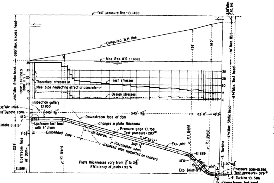
stocks, which were installed as the concrete was placed . . . 4 5. The 15-foot-diameter penstocks at Shasta Dam were embedded
in the concrete of the dam at the upstream ends and were
exposed above ground between dam and powerplant . . . 4
CONTENTS vii
Numbo
6. The full length of the %foot-diameter penstock at Marys Lake Powerplant lies above ground . . . , 7. Economic diameter of steel penstocks when plate thickness is a function of the head . . . 8. Economic diameter of steel penstocks when plate thickness is a function of the head . . . , 9. Friction losses in welded steel pipe based on Scobey’s formula
for 6-year-old pipe and nonaggressive waters . . . 10. Losses for various values of 5 ratios and deflection angles up to900 . . . 11. Head losses in 90° pipe bends as determined for various
R
5 ratios . . . 12. Loss coefficients for divided flow through small tees and branch outlets as determined for various flow ratios &a. . . .
Q
13. Water-hammer values for uniform gate motion and complete closure . . . 14. Equivalent stress diagram . . . 15. A graphical illustration of heads and stresses determined for
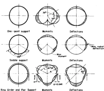
the hydrostatic testing of the Shasta penstocks . . . 16. The Shoshone River siphon crosses the river on a 150-foot span 17. Moments and deflections developed in a pipe precisely full, using various types of supports . . . 18. Formulae and coefficients for the computation of stresses in ring
girders as developed for stiffener ring analyses . . . 19. Formulae and coefficients for the computation of stresses in ring
girders due to earthquake loads . . . 20. Typical ring girder and column support . . . 21. Typical rocker support. The angle yoke is used only for aline- ment during grouting . , . . . 22. Typical sleeve-type expansion joint . . . 23. Flexible sleeve-type expansion joint with two stuffing boxes used
to permit longitudinal temperature movement and trans- verse deflection . . . , . . . 24. Constant diameter bend with the radius of the bend five times the diameter . . . 25. Bend reducing in diameter from 9 feet to 8 feet, the radius equal to four times the smaller diameter . . . 26. Computation method for determining true pipe angle in a com- poundpipebend . . . 27. Loading diagrams for the development of reinforcement of branch outlets . . . 28. Loading diagrams for the development of reinforcement of wye
branchesinpenstocks...
29. Typical internal and external reinforcement for a branch outlet 30. Installation of a piezometer connection in shell of penstock for turbine performance tests . . .
Pans
10 11
11 15 16 18 20 21 22 23 24 25 25 25 26 27 28 29 30 32 33
Vsii CONTENTS
Nwllbw
31. Typical manhole designed for inspection and maintenance . . . 32. Typical monolithic pier construction for rocker supports . . , . . 33. Resolution of forces on pipe anchors . . . 34. Typical concrete anchor . . . 36. Shop fabrication of large diameter penstock . . . , . . 36. Shop joints are welded with automatic equipment . . . 37. Radiographic inspection of welds is performed using portable
X-ray equipment . . . 38. Postweld heat treatment is accomplished by heating in an en- closed furnace . . . 39. Transporting large wye-branch into place . . . 4G. Penstocks being placed, showing temporary support . . . 41. Penstocks installed in Flaming Gorge Dam are encased in mass concrete . . .
LIST OF TABLES
Number
1. Basic conditions for including the effects of water hammer in the design of turbine penstocks . . . , . . 2. Testing methods . . .
34 36 37 38 39 40 42 43 43 44
13 41
Report on Welded Steel Penstocks
Introduction
A penstock is the pressure conduit between the turbine scrollcase and the first open water upstream from the turbine. The open water can be a surge tank, river, canal, free-flow tunnel, or a reservoir. Penstocks should be as hydraulically efficient as practical to conserve available head, and structurally safe to prevent failure which would result in loss of life and property. Penstocks can be fabricated of many materials, but the strength and flexibil- ity of steel make it best suited for the range of pressure fluctuations met in turbine operation.
The design and construction of pressure vessels, such as penstocks, are governed by ap- propriate codes which prescribe safe rules and practices to be followed. Until a special pen- stock code is formulated, steel penstocks should be constructed in accordance with the ASME Boiler and Pressure Vessel Code, Section VIII, Unfired Pressure Vessels, issued by the Ameri- can Society of Mechanical Engineers, herein- after referred to as the ASME code. This code is subject to periodic revision to keep it abreast of new developments in the design, materials,
construction, and inspection of pressure vessels.
Present design standards and construction practices were developed gradually, following the advent of welded construction, and are the result of improvements in the manufacture of welding-quality steels, in welding processes and procedures, and in inspection and testing of welds.
LOCATION AND ARRANGEMENT
The location and arrangement of penstocks will be determined by the type of dam, location of intake and outlet works, relative location of dam and powerplant, and method of river diversion used during construction. At dams requiring tunnels for diversion of the river flow during construction, the penstocks may be placed in the tunnels after diversion has been discontinued and the intake of the tunnel has been plugged. This arrangement was used for the 30-foot lower Arizona and Nevada penstock and outlet headers at Hoover Dam as shown in figure 1, and for the l&foot penstock header at Anderson Ranch Dam as shown in figure 2.
1
POWER PLANT
FXGUXE l.-The SO-fooGdia?neter &now Arieona and Nevada penstock and outlet keadem were in&u&d in two of the diversion tunnels at Hoover Dam. The upper headere were installed in special penstock tunnels. The tunnels were not backfilled with the exception of the inclined portion leading from the intuke tower.
WELDED STEEL PENSTOCKS 3
Outlet pipe No S----.
SECTION
P. I. Horimtol bend---’
Sta 1sto6.03 - El. 3810
PLAN
FIWRE 2.-At Anderson Ranch Dam, the l&foot-d&am- eter penstock and outlet header were installed in the diversion tunnel, which wae not backwed.
For low-head concrete dams, penstocks may be formed in the concrete of the dam. However, a steel lining is desirable to assure watertight- ness. In large concrete dams which have both transverse and longitudinal contraction joints, such as Glen Canyon Dam, steel penstocks are
“-% Penstocks
PLAN
Fxeuav s.-G’ener~J plan and typical pro@ of I s’-
used to provide the required watertightness in the concrete and at the contraction joints.
Figure 4 shows the g-foot penstocks which are embedded in Kortes Dam.
Penstocks embedded in concrete dams, en- cased in concrete, or installed in tunnels back- filled with concrete may be designed to transmit some of the radial thrust due to internal water pressure to the surrounding concrete. More generally, such penstocks are designed to with- stand the full internal pressure. In either case, the shell should be of sufficient thickness to provide the rigidity required during fabrica- tion and handling, and to serve as a form for the concrete. Embedded or buried penstock shells also should be provided with adequate stiffeners or otherwise designed to withstand any anticipated external hydrostatic or grout- ing pressures. At Shasta Dam the upstream portions of the 15-foot penstocks are embedded in the dam, while the downstream portions are
3. Outlet popes
4 ENGINEERING MONOGRAPH NO. 3
-18’ Dia. air vent
,-Main unit trashrack
‘--Penstock oir inlet
,-15-o” Dia. main I unit pensfocks
:Concrete anchor
‘-Line of excavation --I’
FIGURE 4.-Mass concrete of Kortes Dam encased the g-foot-diameter penstocks, which were installed as the concrete was placed.
FIGURE S.-The 15-foot-diameter pen- stocks at Shasta Dam were embedded in the concrete of the dam at the up- stream end8 and were exposed above ground between dam and powerplant.
exposed above ground, between the dam and the powerplant, as shown in figure 5. At other
plants, the entire length of the penstock may be situated above ground, as in figure 6, which
shows the %foot-diameter penstock at Marys Lake Powerplant.
When a powerplant has two or more turbines the question arises whether to use an individ- ual penstock for each turbine or a single pen- stock with a header system to serve all units.
Considering only the economics of the penstock, the single penstock with a header system will usually be preferable; however, the cost of this item alone should not dictate the design.
Flexibility of operation should be given con- sideration because with a single penstock sys- tem the inspection or repair of the penstock will require shutting down the entire plant. A single penstock with a header system requires complicated branch connections and a valve
WELDED STEEL PENSTOCKS 5
TYPICAL SECTION AT SUPPORT
FIGURH B.-The full length of the d-foot-diameter pen- stock at Marys Lake Poweqdant lies above ground.
to isolate each turbine. Also, the trashracks and bulkhead gates will be larger, resulting in heavier handling equipment. In concrete dams it is desirable to have all openings as small as possible. The decision as to the pen- stock arrangement must be made considering all factors of operation, design, and overall cost of the entire installation.
Proper location of the penstock intake is im- portant. In most cases the intake is located at the upstream face of the dam, which provides short penstocks and facilitates opera- tion of the intake gates. In some cases the penstock intake may be situated in an in- dependent structure located in the reservoir, as at Hoover and Green Mountain Dams, where diversion tunnels or topographic conditions influenced the arrangement. Regardless of arrangement, the intake should be placed at an elevation sufficiently below low reservoir level and above the anticipated silt level to allow an uninterrupted flow of water under all condi- tions. Each intake opening is protected against floating matter by means of a trash- rack structure and is controlled by suitable gates.
To prevent the development of a partial vacuum during certain operating conditions, penstock profiles from intake to turbine should, whenever possible, be laid on a continuous slope.
ECONOMIC STUDIES
A penstock is designed to carry water to a turbine with the least possible loss of head consistent with the overall economy of installa- tion. An economic study will size a penstock from a monetary standpoint, but the final di- ameter should be determined from combined engineering and monetary considerations. An example would be an installation where the economic diameter would require the use of a surge tank for regulation, but a more economi- cal overall installation might be obtained by using a penstock considerably larger than the economic diameter, resulting in the elimination of the surge tank.
Voetsch and Fresen (1) l present a method of determining the economic diameter of a pen- stock. Figure 7 was derived from their method, and figure 8 is an example of its use.
Doolittle (2) presents a method for determining the economic diameters of long penstocks where it is economical to construct a penstock of varying diameters. This “step by step”
method requires considerable time but should be considered for final design for long pen- stocks.
All the variables used in an economic study must be obtained from the most reliable source available, keeping in mind that an attempt is being made to predict the average values of all variables for the life of the project. Special attention must be given to the “plant factor”, figure 7, as this item materially affects the cal- culations.
HEAD LOSSES IN PENSTOCKS
Hydraulic losses in a penstock reduce the effective head in proportion to the length of the penstock and approximately as the square of the water velocity. Accurate determination of these losses is not possible, but estimates can be made on the basis of data obtained from pipe flow tests in laboratories and full-scale installations.
‘Numbers in parentheses refer to literature cited in mxtlon, “A Selected Bibliography and References”. at the end of thla mono- mwh.
ENGINEERING MONOGRAPH NO. 3
t=
a : Cost of pipe per lb., instolled, dollars.
8 = Diometer multiplier from Groph 6.
b = Volue of lost power in dollorr per k wh.
D = Economic diometer in feet.
e = Overall plant efficiency.
eJ = Joint efficiency.
f = Loss factor from Groph A.
NOTATION
Ii = Weighted overage heod including woter hommer. (based an design head )
KS = Friction coefficient in Scobey’s formula (0.34).
n = Ratio of overweight to weight of pope shell.
Cl = Flow in cubic feet per second. (ot design head of turbine) r z Ratio of onnuol cost ta”a”( see explanotion)
sg = Allowable tension, p.s.i
t = Weighted overage plate thickness(ot design head) for total length, t, 2 Averoge plote thickness for length L,.
EXPLANATION AND EXAMPLE
L,t,+L*t2+LJts’...+Lntn
L,+ Let Ls+...+ Ln t4
% o a M, ~ 0. 8 M. per foot Cast per foot of pipe
0.8 M = Cost of mointainmg interior ond exterior surface Oreo of pipe( inside surface oreo for embedded pipe, inside ond outside surface areo for exposed pipe ) per year.
Depreciation = See Reclamation Monual, Vol. PI Fewer, page 2,4,llD.
r : Interest t Depreciation l % 0. 8 M.
ASSUME
Example for penstock Q = I28 CFS
Dia.: 5’-0” Avg. plate = f Value of power per kwh:‘0.005- b Cost of steel pipe mstolled=sO.27/Ib = a Plont factor (see Graph A):0.75(f~0.510) Interest = 3% n= 0.15
Depreciation = 0.005135
0.8 M.=‘0.02 per sq.ft. Weight/ foot=l57lx lO.2= 160.24 Ibs.
Gast/foot=l6a24x0.27=*43.26
L
r
L,:22$ L,= 150; L,=(50’, L,ZlOO’
H,=fJO’; H,=l20’, Hs=l70, H,= 2301i H,=240’
” I ~~lL,t(~~Lz+~~)L,tlH~~L, _ L, t Lx + L, + L,
0,8M,~u225x15.71)~~4wx 15.71x2)10.02 z)o,5, 625
= 0.03 t0.005135+0.0119=0.0470 % 0.8 M.= sz o.ollg Kz %efsgejb -I
or( I+n)
0.34x095x 0.510x15.000x0.90x0.00~~ 690 0.27x 0.0470 x I.15
156.4’
5
9: 1.285 (from GmphB);D’=3.7(from GmphG); Economic dia.: I.285 x3.7= 4.75 ( use 4’-10”dia.)
NOTE: Calculated economic diameter should be very close to ossumed diameter as it is in this exomple. The problem should be reworked until this condition exists Depreciation is bosed on the accumulation of on onnual smkrng fund eorning 3%
interest required to replace 50% of the pipe in 45 years, The annuol poyment required is equal to 0.005135 times the first cost.
FIGUREI 8.-Economic diameter of steel penstocks when plate thickness is a function of the head.
8 ENGINEERING MONOGRAPH NO. 3
The various head losses which occur between reservoir and turbine are as follows:
1. Trashrack losses 2. Entrance losses
3. Losses due to pipe friction 4. Bend losses
5. Losses in valve and fittings.
Losses through trashracks at the intake vary according to the velocity of flow and may be taken as 0.1, 0.3, and 0.5 foot, respectively, for velocities of 1.0, 1.5, and 2.0 feet per second.
The magnitude of entrance losses depends upon the shape of the intake opening. A cir- cular bellmouth entrance is considered to be the most efficient form of intake if its shape is properly proportioned. It may be formed in the concrete with or without a metal lining at the entrance. The most desirable entrance curve was determined experimentally from the shape formed by the contraction of a jet (vena contracta) flowing through a sharp- edged orifice. For a circular orifice, maximum contraction occurs at a distance of approxi- mately one-half the diameter of the orifice.
Losses in circular bellmouth entrances are estimated to be 0.05 to 0.1 of the velocity head.
For square bellmouth entrances, the losses are estimated to be 0.2 of the velocity head.
Head losses in pipes because of friction vary considerably, depending upon velocity of flow, viscosity of the fluid, and condition of the inside surface of the pipe. Among the con- ventional pipe flow formulae used for the computation of head losses, the Scobey, Man- ning, and Hazen-Williams formulae are the most popular. For large steel pipe the Scobey formula is favored ; for concrete pipe, the Manning formula ; and for cast-iron pipe in waterworks, the Hazen-Williams formula.
The Scobey formula(3), derived from ex- periments on numerous steel pipe installations, is expressed as follows:
H*=K+. . . . ..,... (1) in which
HP= head loss due to friction in feet per 1,000 feet of pipe
Ks = loss coefficient, determined experimen- tally
V =velocity of flow in feet per second D =diameter of pipe in feet.
Values for I& vary for different types of pipe.
For new continuous interior pipe unmarred by projections on the inside (as for butt-welded pipe) a value of 0.32 may be used. Scobey gives values of Ks for old pipe allowing for deterioration of the interior surface. To allow for deterioration a value of Ks=0.34 is usually assumed in design for pipes whose interior is accessible for inspection and maintenance.
Friction losses for this value of KS, for pipes up to 10 feet in diameter, can be read from the chart, figure 9. For pipes too small to permit access for maintaining the interior coating a value of Ks=0.40 is usually assumed.
Bend losses vary according to the shape of the bend and the condition of the inside sur- face. Mitered bends constructed from plate steel no doubt cause greater losses than smooth curvature bends formed in castings or concrete ; however, there is no way to evaluate such effects since data on actual installations are very meager. Laboratory experiments on very small size bends with low Reynolds numbers are not applicable to large size bends with high Reynolds numbers. When water flows around a bend, eddies and secondary vortices result, and the effects continue for a considerable distance downstream from the bend. In sharp angle bends the secondary vortex motion may be reduced by guide vanes built into the bend.
Thoma’s (4) formula is based on experiments made at the Munich Hydraulic Institute with 1.7-inch-diameter smooth brass bends having Reynolds numbers up to 225,000, as shown on the chart in figure 10, and is expressed as:
Ha=CL...
2g (2)
where
H,, = bend loss in feet
C =experimental loss coefficient, for bend loss
V =velocity of flow in feet per second.
The losses shown in figure 10 vary according to the R/D ratio and the deflection angle of the bend. An R/D ratio of six results in the lowest head loss, although only a slight de- crease is indicated for R/D ratios greater than
WELDED STEEL PENSTOCKS
FRICTION LOSS - FEET PER 1000 FEET
,URE 9-Fmktion losses in welded steel pipe based on Scobey’s formula for &year-old pipe and nonaggressive wat em.
IO ENGINEERING MONOGRAPH NO. 3
.26
.24
; .I6 W i?
E .I4 g o .I2 : 2 .I0
.06
.02
0’ 5” IO” 15“ 20” 25* 30” 35O 40=’ 45.’ 50” 55’ 60’ 65’ 70’ 75=’ 80’ 65’
DEFLECTION ANGLE A0
Fxoum lo.-LO88e8 for vari5248 value8 of g ratios and d43flection andes UP to 90'.
four. This relationship is also indicated by the curves of figure 11, which were plotted from experiments with 90” bends, As the fabrication cost of a bend increases with in- creasing radius and length, there appears to be no economic advantage in using R/D ratios greater than five.
Head losses in gates and valves vary accord- ing to their design, being expressed as:
H,=K-& . . . (3) in which K is an experimental loss coefficient whose magnitude depends upon the type and size of gate or valve and upon the percentage of opening. As gates or valves placed in pen- stocks are not throttled (this being accom-
plished by the wicket gates of the turbines), only the loss which occurs at the full open condition needs to be considered. According to experiments made at the University of Wisconsin (5) on gate valves of l- to Z-inch diameter, the coefficient K in Equation (3) varies from 0.22 for the l-inch valve to 0.065 for the 12-inch valve for full openings. For large gate valves an average value of 0.10 is recommended ; for needle valves, 0.20 ; and for medium size butterfly valves with a ratio of leaf thickness to diameter of 0.2, a value of 0.26 may be used. For sphere valves having the same opening as the pipe there is no reduction in area, and the head loss is negligible.
WELDED STEEL PENSTOCKS II
-Rough pipe
-Smooth pipe
0 012345670 9 IO
FRIES ll.-Head bsoea in so0 pipe benda as &to+
minsd fm uariuu.9 E ratios.
Fxoua~ m-LO88 CO&i8Td8 for dbidd &HO thmwh
amall tees and breach tnd8t8 a.8 da- fW d
0488 jtOl8 Vf3tiO80".
Q
Fittings should be designed with smooth and streamlined interiors since these result in the least loss in head. Data available on losses in large fittings are meager. For smaller fit- tings, as used in municipal water systems, the American Water Works Association recom- mends the following values for loss coefficients, K; for reducers, 0.25 (using velocity at smaller end) ; for increasers, 0.25 of the change in velocity head ; for right angle tees, 1.25; and for wyes, 1.00. These coefficients are average values and are subject to wide variation for different ratios between flow in main line and branch outlet. They also vary with different tapers, deflection angles, and streamlining.
Model tests made on small tees and branch out- lets at the Munich Hydraulic Institute show that, for fittings with tapered outlets and de- flection angles smaller than 90” with rounded corners, losses are less than in fittings having cylindrical outlets, 90” deflections, and sharp corners. (See figure 12.) These tests served as a basis for the design of the branch connec- tions for the Hoover Dam penstocks.
EFFECT OF WATER HAMMER
Rapid opening or closing of the turbine gates produce a pressure wave in the penstock called water hammer, the intensity of which is proportional to the speed of propagation of the pressure wave produced and the velocity of flow destroyed. Joukovsky’s fundamental equation gives the maximum increase in head for closures in time less than 2L/a seconds:
AH=-!%
8 . . . ..F*!. . . (4) in which
AH =maximum increase in head a =velocity of pressure wave
L=length of penstock from forebay to turbine gate
v =velocity of flow destroyed g =acceleration due to gravity.
From this formula, which is based on the elastic water-hammer theory, Allievi, Gibson, Durand, Quick, and others developed inde- pendent equations for the solution of water- hammer problems (6).
ENGINEERING MONOGRAPH NO. 3 In his notes published in 1903 and 1913,
Alhevi introduced the mathematical analysis of water hammer, while M. L. Bergeron, R. S.
Quick, and R. W. Angus developed graphical solutions of water-hammer problems which are more convenient to use than the analytical methods. A comprehensive account of methods for the solution of water-hammer phenomena occurring in water conduits, including graphi- cal methods, was published by Parmakian (7).
For individual penstocks of varying diameter, the pressure reflections at points of change in diameter complicate the problem.
However, if the varying diameter is reduced to a penstock of equivalent uniform diameter, a close estimate can be made of the maximum pressure rise. For penstocks with branch pipes, it is necessary to consider the reflection of pressure waves from the branch pipes and dead ends in order to determine the true pres- sure rise due to velocity changes.
As the investment in penstocks is often con- siderable, they must be safeguarded against surges, accidental or otherwise. Surges of the instantaneous type may develop through resonance caused by rhythmic gate movements, or when the governor relief or stop valve is improperly adjusted. A parting and rejoining of the water column in the draft tube or a hasty priming at the headgate may also cause surge waves of the instantaneous or rapid type.
Adjustments iw the profile of a penstock may be necessary to prevent the development of a vacuum and water column separation during negative pressure surges. As water-hammer surges occurring under emergency conditions could jeopardize the safety of a penstock if they are not considered in the design, their magni- tude should be determined and the shell thick- ness designed for the resultant total head.
Stresses approaching yield-point values may be allowed. By using ductile materials in the penstock, excessive surge stresses may be ab- sorbed by yielding without rupture of plates or welds. Design criteria for including the effects of water hammer in penstock and pump discharge line installations, as used by the Bureau of Reclamation, is shown in table 1.
Surge tanks are used for reduction of water hammer, regulation of flow, and improvement
in turbine speed regulatipn. A surge tank may be considered as a branch pipe designed to ab- sorb a portion of the pressure .wave while the remainder travels upstream toward the fore- bay. When located near the powerhouse, it provides a reserve volume of water to meet sudden load demands until the water column in the upper portion of the penstock has time to accelerate.
When the length, diameter, and profile of the penstock have all been determined, con- sidering local conditions and economic factors, the selection of a minimum closure time for the turbine gates will require a compromise be- tween the allowable pressure variation in the penstock, the flywheel effect, and the permis- sible speed variation for given load changes on the unit.
With reaction turbines, synchronous relief valves, which open as the turbine gates close, may be used to reduce the pressure rise in the penstock. Reduction of pressure rise is proportional to the quantity of water released.
As relief valves are usually designed to dis- charge only a portion of the flow, this portion is deducted from the total flow in computing the reduced velocity and the corresponding pressure rise.
Pressure Rise in Simple Conduits
With instantaneous gate closure, maximum pressure rise in penstocks of uniform diameter and plate thickness occurs at the gate ; from there, it travels undiminished up the conduit to the intake or point of relief. For slower closures which take less than 2L/a seconds
(L = length of penstock ; a = velocity of pressure wave), the maximum pressure rise is trans- mitted undiminished along the conduit to a point where the remainder of the distance to the intake is equal to Ta/2 (T=time for full gate stroke), from which point to the intake the pressure rise diminishes uniformly to zero.
With uniform gate closure equal to or greater than the critical time, ZL/a, the maximum pressure rise occurs at the gate, from which point it diminishes uniformly along the length of the penstock to zero at the intake. An anal-
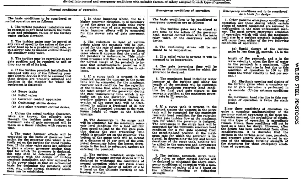
TABLE l.-Basic conditions for including the effects of loater hummer in the design of turbine penstocks.
The basic conditions for ineludIng the &acts of water hammer in the design of turbine Denstock instaIlat.ions are divided into normal and emergency conditions with s&able factors of safety assigned to each type of oDeratIon.
Nomad conditions of omwation
1. The turbine Denstock installation may be werated at any head between the maxi- mum and minimum values of the forebay water surface elevation.
2. The turbine eaten may be moved at any rate of steed by the action of the BOV- emor head UD to a Dredatermined rate. or at a slower rate by maneal control through the aorili relay vaIve.
2. The turbine may be operating at any wte Dosition and be required to add or drop any or ail of its load.
4. If tbe turbine penstock installation is eanipDed with any of the following Dres- sure control devices it will be assumed that these devices are properly adjusted and function in tbe manner for which the equipment is designed:
(a) Surge tenks (b) Relief valves
(e) Governor control SDParatus (d) Cushioning stroke device (e) Any other pressure control device.
6. Unless the actual turbine character- istics are known. the efieetive area through the turbine gates during the mruimum rate of gate. movement will be Upk as * linear relation wxth resDect to 6. The water hammer &ecta will be computed on the basis of governor head action for the governor rate which is BE- anally set on the turbine for speed regal&
tion. If the r&w valve stoos are adinsted to Bive a slower governor setting than that for which the governor is designed, this rate shall be determined DriOr to Droceeding with the design of turbine penstock installation and later adhered to at the Dower plant so that an economical basis for designing the penstoek. sclDu WE=% etc.. Under ma-maI ODersting wndi- tions can be established.
I. In those instances where. due to a higher reservoir elevation. it is necessary to set the st.,DS on tbe main relay valve for a slower rate of gate movement. the water hammer elTen3.a will be computed foe this slower rata of gate movement 8. The reduction in head at various points along the penstock will be corn- puted for the rate of gate opening which is adually set in the governor in those cases where it aDDears that the u,mfiIe of tbe Denstock is unfavorable. This mjni- mum Dressure will then be used as a bqsis for normaI design of the pentik to in- sure that subatmospheric Dressures will not cause a penstock failure due to col- IaDse.
9. If a surge tank is Drasent in the penstock system the upsurge in the surge tank will be computed for the maximum reservoir level condition for the rejection of the turbine flow which correspondb to the rated output of the generator during the gate transversing time which is ac- tually set on the governor. Unless an overflow sDiIlway is provided the top d- evation of the surge tank will be deter- mined by adding a freeboard of 20 Dar cent of the com~utd upsurge to the max- imum height of water at the highest IlDSnrge.
10. The downsurge in the surge tank will be e0m~ut.d for the minImum reser- voir level condition for a load addition from sDeed-no-load to the full Bate Do&
tion during the sate traversing iime which is actually set on the governor. The bottom of the surge tank will be Iocatsd at a distance of 20 per cent of the com- DUti downsurge b&w the lowest down- surm in the tank to safeguard against air wtering the Denstock.
11. The turbine, pens&k. surge tank.
and other DRaWre control devices will be designed to withstand the conditions of normaI operation which are given above with a minImum factor of safety of 4 to 5 based on the ultimata bursting or col- laDsing strenpth.
-
Emergsncu conditiona of operation
The bssic conditions to be considered as WlergeneJT ODeration are as foIIows:
1. The turbine gates may be closed at any time by the action of the governor head. manual control knob with the main relay valve. or the emergency solenoid device.
2. The cushioning stroke will be as- sumed t.0 be inoperative.
a. If a relief valve is Dresent it, will be assumed to be inoperative.
4. The Bate traversing time will be taken as the minimum time for which the governor is designed.
6. The maximum head including water hammer at the turbine and along the length of the panstock will be computed for the maximum reservoir head condi- tion for 5naI DWt gate closure to the zero-gate position at the -imum gover- nor rate in 2& seconds.
a
6. If a surge tank is present in the Denstock system the upsurge in the surge tank wiII be eOmDUted for the maximum reservoir head condition for the rejection of fnil gate turbine flow at the maximum rate for which the governor Is designed.
The downsurge in the surge tank will be computed for the minimum r-air head condition for a fuI1 gate oDening from the speed-n*Ioad position at tbe maxi- mum rate for which the governor is de- sign+. In determining the tom and bottom elevatmns of the surge tank, nothing will be added to the UPsurgea and downsurges for this -‘3EZX,CY eO&it&X, Of OD-- tion.
7. The turbine. Denstuck. surge tank.
relief valve. or other control devices will be designed to withstand the above emer- BemY wndltions of operation with a min- imumfa+rofsafetqof2288an
thgeh~mIbte bmxtmg or C0Sapaing
Emarmncu wnditious +wt to be comideed as a basis for design
1. Other Doesible emereency conditions of operation are those during which certain pieces of control equipment are assumed to malfunction in the most unfavorable man- ner. The most severe emergency condition of o~aration which wiII yield the maximum head rise in a turbine Denstock installation will oeeur from either of the two following conditions of operation:
(a) Rapid &sure of the turbine gatesinIessthan2&seconds, (Lbthe length of the Denatik and a is the wave velocity). when t& flow of water in the Denstock is a maximum. (The maximum head rise in feet due to this wndition of oDeration is 100 to 126 times the water velocity in feet per sac- and. )
(b) Rhythmic opening and closing of the turbine gates when a complete cy- cle of gate owration is performed in 4L seconds. (Under extreme condIt,icms -
tie maximum head rise due to this con- ft$) of OD-tiOn is twice the static Since these conditions of operation re- mire a complete malfunctioning of the gowrnor control apDaratus at the most un- favorable moment. the DrobabiIIty of obtain- ing this t4pe of. oDeration is exceedingIy remote. Hence. these wnditioM will not. be used as a basis for design. However. after Se design has been eatabIiied from other considerations. it is desimbIe that the stresses in the turbine scrdl case. ~enstock.
Bnd Dressme contrd devices be not in ax- :ess of the ultimate bursting strength of
;he structures for these emergene~ con%- tiOns Of ODeratiOn.
w
14 ENGINEERING MONOGRAPH NO. 3 Ysis of pressure time curves shows that the
maximum pressure rise is determined by the rate of change of velocity with respect to time.
Maximum pressure rise will develop in a pen- stock when closure starts from some relatively small percentage of full stroke so that some finite velocity is cut off in a time equal to 2L/a seconds.
The governor traversing time is considered to be the time required for the governor to move the turbine gates from the rated capacity position to the speed-no-load position. As the rate of governor time is adjustable, it is im- portant that a minimum permissible rate be specified if maximum pressure rise in the pen- stock is to be kept within design limits.
Water-hammer conditions should be deter- mined for the unit operating at rated head and under maximum static head. The highest total head, consisting of static and water-hammer heads, should be used for computing plate thickness of the penstock.
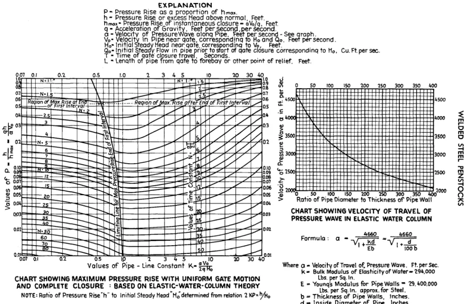
R. S. Quick (6) simplified water-hammer computations by using a pipeline constant, K, and a time constant, N, in the equations
(similar to Allievi’s) which determine pressure rise, or water hammer, resulting from instan- taneous closure. The chart in figure 13 shows the relative values of K and P (equal to h) for various values of N. Also in-
h ..I
eluded is a chart which shows the velocity, a, of the pressure wave in an elastic water column for various ratios of penstock diameter to thickness. Figure 14 gives only the maximum values of P for uniform gate motion and com- plete closure. It covers a range of closures from instantaneous to 50 intervals, and a range of values of K from 0.07 to 40, which includes the majority of practical cases. The nearly vertical curve shows the limiting value for maximum pressure rise at the end of the first time interval, 2L/a. Values of pressure rises to the left of this line attain their maximum values at the end of the first interval.
PIPE SHELL
As has been stated, penstocks should be c designed to resist the total head consisting of
static and water-hammer heads. Working stresses which will assure safety under all ex- pected operating conditions should be used.
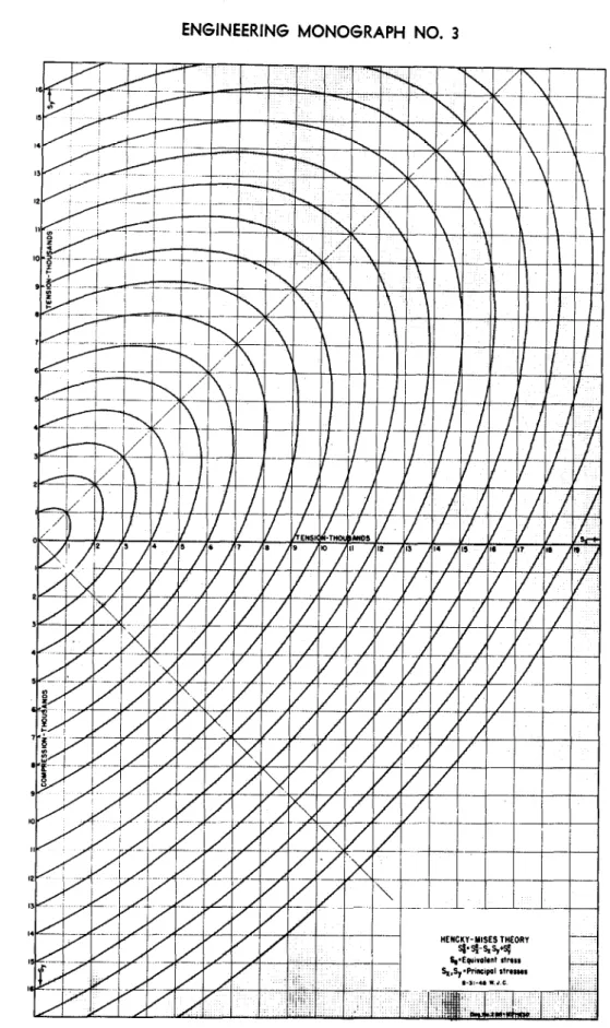
However, stresses approaching the yield point may be used in designing for emergency con- ditions. For penstocks supported on piers in open tunnels or above the ground, allowance should be made for temperature and beam stresses in addition to the stresses due to in- ternal pressure. The diagram shown in figure 14 permits a quick determination of equivalent stresses if principal stresses are known. The diagram is based on the Hen&y-Mises theory of failure, sometimes called the shear-distor- tion or shear-energy theory. The plate thick- ness should be proportioned on the basis of an allowable equivalent stress, which varies with the type of steel used. The ASME code gives maximum allowable tensile stresses for various types of steels.
The hoop tension, S, in a thin shell pipe, due to internal pressure is expressed as:
s=* . . .
. . . (5) in whichD=inside diameter of pipe in inches p=internal pressure in psi
t =plate thickness in inches e =efficiency of joint.
Regardless of pressure, a minimum plate thickness is recommended for all large steel pipes to provide the rigidity required during fabrication and handling. For penstocks the desired minimum thickness for diameter, D, may be computed from the formula:
&in= D+zo..
. . .400 (6)
A thinner shell may in some cases be used if the penstock is provided with adequate stiff- eners to prevent deformation during fabrica- tion, handling, and installation.
Joint efficiencies for arc-welded pipe depend on the type of joint and the degree of examina- tion of the longitudinal and circumferential joints. The ASME code stipulates a maximum allowable joint efficiency of 100 percent for double-welded butt joints completely radie- graphed, and of 70 percent if radiographic examination is omitted. Corresponding joint efficiencies for single-welded butt joints with
EXPLANATION
0.6 0.5 Ok 0.3 0.2
0.10
0.09
E!
0.06
0.05
0.04
0.03
0.02
O.OlW - 7\L- -NJ l-+-J- ’ ’
007 0.1 0.2 0.5 IO 2 3 45
Values of Pipe - Line Constant K- $$
0
CHART SHOWING MAXIMUM PRESSURE RISE WITH UNIFORM GATE MOTION AND COMPLETE CLOSURE : BASED ON ELASTIC-WATER-COLUMN THEORY
NOTE: Ratio of Pressure Rise’h” to Initial Steady HeadrH~determined from relation 2 Kp~b~,
Cu. Ft. per sec.
CHART SHOWING VELOCITY OF TRAVEL OF PRESSURE WAVE IN ELASTIC WATER COLUMN
Formula : a - -
*=vyfTgb
Where o - Velocity of Tmvel of. Pressure Wave. Ft. per Sec.
k- Bulk Modulus of Elasticity of Water- 294.000 Lbs. per Sq. In.
E = Younq’s Modulus for Pipe Walls = 29.400.000 Lbs. per Sq. In. approx. for Steel.
b = Thickness of Pips Walls, Inches.
d = Inside Diameter of Pipe, Inches.
FIGURE 13.-Water-hamm.er values for uniform gate motion and complete closure.
VI
I6 ENGINEERING MONOGRAPH NO. 3
NENCKY-YISES THEORY
FIGURE 14.-Equivalent stress diagram