Download firmware, associated files (such as AOP, EDS, and DTM) and access product release notes from the Product Compatibility and Download Center at rok.auto/pcdc.
For all ring types, we recommend that you limit a DLR network to 50 or fewer nodes. For more information on how to obtain fault location information, see Chapter 5, Monitoring the DLR Network. If you fully bridge your DLR network without a supervisor configured, the network may experience a network storm.
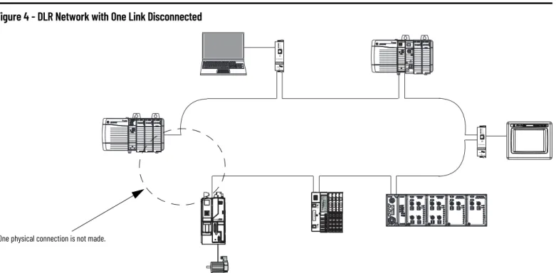
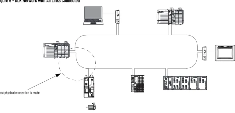
IMPORTANT If your DLR network contains redundant gateways, you must complete the redundant gateway configuration before connecting the uplink ports to the external network. After configuring a ring supervisor, you must complete the physical connection between all nodes to establish a complete and working DLR network. IMPORTANT If you fully connect your DLR network without a supervisor configured, a network storm may occur.
IMPORTANT If your DLR network contains switches, you must complete the DLR configuration of all switches before completing the physical connection between all nodes. IMPORTANT If your DLR network contains redundant gateways, complete the redundant gateway configurations before connecting the uplink ports to the external network.
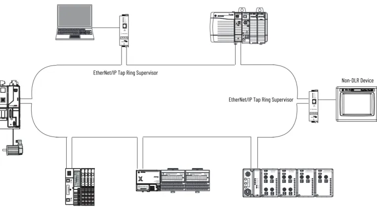
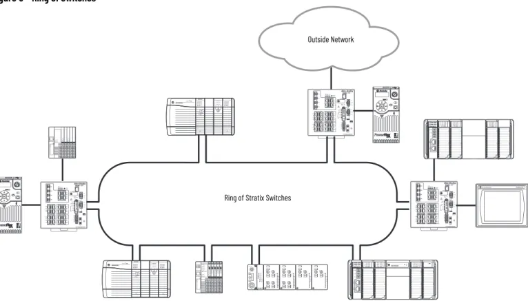
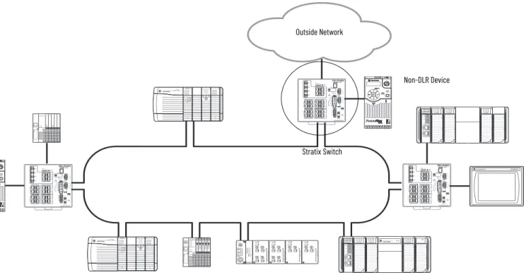
When configured as a ring supervisor, a Stratix® switch provides consolidated status and diagnostics for the DLR network. A Stratix switch connects the ring to the outside network and also connects a non-DLR device to the ring. A DLR network can consist exclusively of DLR-capable switches and still support a high-speed convergence time of 3 ms or less.
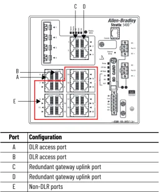
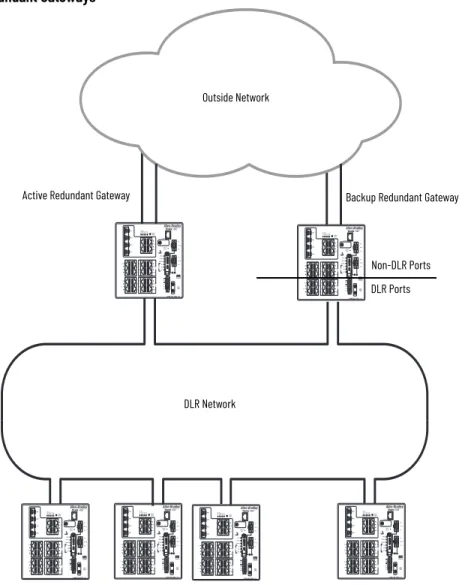
The network can switch from the active gateway to the standby gateway in 14ms…6.1 seconds depending on the redundant upstream network protocol. IMPORTANT The redundant gateway feature requires that all devices in the ring are compatible with the redundant gateway. When the switch is acting as an active redundant gateway, traffic on the switch assigned to VLAN 1 can flow between all ports (A, B, C, D, and E).
IMPORTANT Both the active and backup gateway switches and all devices on the ring must have firmware that supports redundant gateways. You can configure some Stratix switch models as a DLR DHCP server for devices in a ring. A DLR DHCP server assigns IP addresses to devices based on their positions in the ring.
The primary DHCP server is always index number 1. Starting with the primary DHCP server, the index numbers increase up the ring in order from the device connected to the lowest DLR port on the primary server. If enabled, the standby DLR DHCP server runs on the standby ring controller and automatically obtains its lookup table from the active DLR DHCP server on the active ring controller. The backup DLR DHCP server on the backup ring controller becomes the active DLR DHCP server.
IMPORTANT If you have an application that includes a backup DLR DHCP server, other DHCP features (including DHCP persistence) are not supported on the primary DHCP server or the backup DHCP server. IMPORTANT Do not configure a DHCP table or DHCP address pool on the backup DLR DHCP server. The following example shows two rings on the same VLAN and one ring on a separate VLAN.
The same switch also acts as the primary DHCP server for ring devices on CIP VLAN 100. Another Stratix 5400 switch is located within the ring with CIP VLAN 100 and acts as the backup DHCP server for that ring. Traffic remains on the same VLAN as it passes through each switch in the ring.
The remote ports on the routing device in the outside network are configured to allow the same VLANs as the connected local ports. In the example shown in Figure 28, HSRP provides redundancy from the uplink ports on the redundant ports to the outside network.
Enter the device's IP address in a web browser to open the device's web page. Enter the IP address of the switch in a web browser and log in to Device Manager. The faceplate files are available in the Network Device Library accessible from the Product Compatibility and Downloads Center at rok.auto/pcdc.
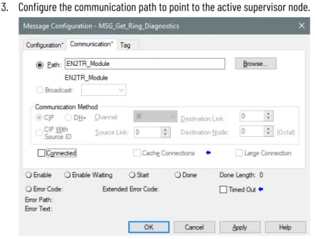
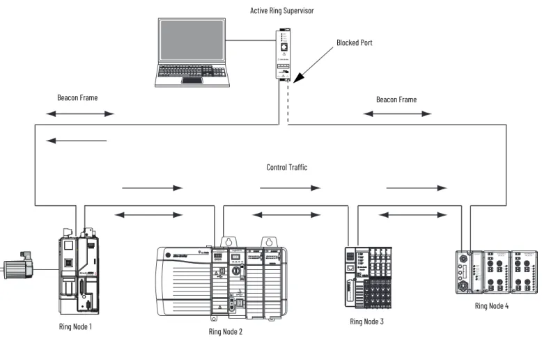
Get the last active node at the end of a chain through port 1 of an active ring supervisor during a ring fault. Get the last active node at the end of a chain through port 2 of an active ring supervisor during a ring fault. The network status attribute returns the network status based on the view of the network from the device.
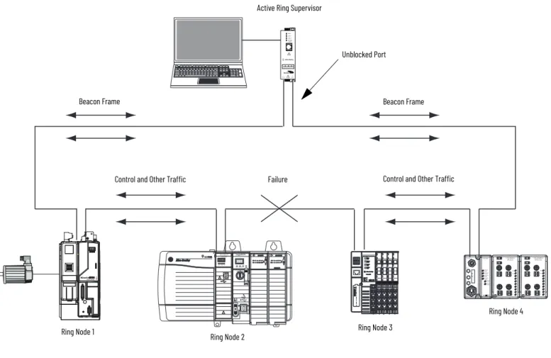
The Last Active Node on Port 1 attribute contains the IP address and Ethernet MAC address of the last node reachable through port 1 of an active ring supervisor. When the device is not activated as a ring supervisor or operating as a backup supervisor, the IP address and Ethernet MAC address is 0. The Last Active Node on Port 2 attribute contains the IP address and Ethernet MAC address of the last node reachable through port 2 of an active supervisor of the ring.
When the device is not enabled as a ring supervisor, or is operating as a backup supervisor, the IP address and Ethernet MAC address are 0. 1 Ring The network topology attribute specifies the ring mode (1) when a supervisor-enabled device is enabled as a ring supervisor, except when the device cannot support the current ring operational parameters. 0 Normal operation The devices detect that the network is functioning normally in both ring and linear topology modes.
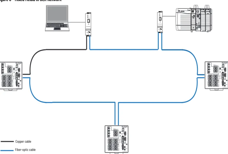
Valid only if the network topology mode is Ring and the node is the active ring supervisor. When measuring the performance of your network during outages, we recommend that you consider network recovery time. This recovery time is based on 2 km (6561 ft) fiber optic cable segments between nodes in the network.