CHAPTER 13
Fission Reactor Applications of Carbon
TIMOTHY D. BURCHELL
Metals and Ceramics Division Oak Ridge National Laboratory
Oak Ridge, Tennessee 37831-6088, USA
1 The Role of Carbon Materials in Fission Reactors I . I Nuclear fission - basic concepts
Nuclear (fission) reactors produce useful thermal energy from the fission (or disintegration) of isotopes such as 92U235, g2UB3, and 94Pu239. Fission of a heavy element, with release of energy and further neutrons, is usually initiated by an impinging neutron. The fission of 92V35 may be written:
92V35
+
,,n'-
92TJ236*-
A+
B+
n + energy.The two fission fragments "A" and "B" will vary over a range of mass numbers fiom about 74 to 160, there being a whole range of possible reactions. Although an integral number of neutrons is emitted for any one fission, the average yield per fission (when all possible methods of fission are considered) is about 2.5 neutrons.
The neutrons emitted by the fission reactions can be described by a Maxwellian distribution in energy, with a mean value of about 2 MeV. The total amount of energy given up per atom fissioned is of the order of 200 MeV, which is distributed approximately as indicated in Table 1.
Table 1. Energy distribution from the fission of a UZ3' atom [I]
Nuclear Process Energy (MeV)
Kinetic energy of fission fragments Kinetic energy of fission neutrons
170 6 5 5
Instantaneous y-rays 6
Radioactive decay of fission fragments, p energy Radioactive decay of fission fragments, y energy
The exact distribution of energies will depend upon the actual fission fragments produced. However, it can be seen from Table 1 that the bulk of the energy is obtained as kinetic energy of the fission fragments, which is degraded to heat by successive collisions within the body of the uranium fuel mass in which the fission took place. Moreover, a significant fraction of the heat is produced outside the fuel. The fission neutrons give up their kinetic energy by elastic collisions, typically within the moderator, and the y-ray energy is absorbed by the bulk of the reactor materials outside of the fuel (moderator, pressure vessel, and shielding).
Finally, some of the energy release occurs slowly, through the radioactive decay of fission products. This heat release is not, therefore, instantaneously available in new fuel, but will build up with irradiation until the production of new fission products by neutron bombardment just balances their radioactive decay.
Conversely, with irradiated fuel, there is a significant release of radioactive decay heat after irradiation is finished (after-heat).
Neutron reaction cross-sections (the probability of a given nuclear reaction taking place) are functions of neutron velocity (energy). Most cross-sections increase as neutron velocity (u) decrease, following a l/u law, i.e., the longer a neutron dwells in the vicinity of a nucleus as it passes, the more probable it is that it will react with that nucleus. It is, therefore, advantageous in the operation of a nuclear reactor to slow the fission neutrons (referred to as "fast" neutrons) to lower (thermal) energies (-0.025 eV at room temperature), corresponding to a neutron velocity of 2.2 x lo5 c d s . The slowing down (or thermalization) process is also termed
"moderation". In a thermal reactor the fission neutrons leave the fuel with high energy, i.e., they are fast neutrons, and are slowed down outside the fuel in a non- absorbing medium called a "moderator." The nuclear fuel is a mixture of 92U238, 92U23s, and 92U234. Natural uranium contains the isotopes 92Uu8, 92U235, and 92U234 in the proportions 99.282, 0.712, and 0.006%, respectively. 92U23s will undergo fission on capturing a neutron of any energy but, as discussed above, it is more likely to capture low-energy (slow) neutrons. g2Uz3' will undergo fission with neutrons of energy > 1.1 MeV, and will capture (absorb) intermediate energy neutrons to form ,Puu9. Once thermalized (moderated) the neutrons may be returned to the fuel, where they are unlikely to be captured by 92U238, but will most probably cause fission in the 92U235. Additionally, mixtures of fisile and fertile fuel have been utilized. In such cases, neutron absorption converts the "fertile" fuel (such as thorium) to a fissile fuel. A thermal reactor may, therefore, be fueled with natural uranium or, if the structural materials of the reactor absorb too many neutrons, slightly enriched (in g2U235) uranium.
1.2 Requirements of a good moderator
A good moderator should possess the following properties:
The moderator must not react with neutrons because if they are captured in the moderator they are lost to the fission process, leading to an inefficient reactor.
Neutrons should be slowed down over short distances and with few collisions in the moderator, i.e., the average neutron-moderator collision must lead to a large neutron energy loss. The chance of neutron capture by V3* resonances, moderator impurities, or by absorbing reactor structural materials is thus reduced. The resultant efficient neutron economy and physically small reactor help to minimize construction costs.
The moderator should be inexpensive, yet must have satisfactory structural properties.
The moderator must be compatible with the other structural materials used in the construction of the reactor. It should not corrode or erode, even under the influence of radiation.
The moderator must not undergo deleterious physical or chemical changes when bombarded with neutrons.
A good moderator must efficiently thermalize fast neutrons. This thermalization process occurs by neutron-nucleus elastic collisions. It can be shown from a simple consideration of Newton's laws that maximum energy loss per collision occurs when the target nucleus has unit mass, and tends to zero energy loss for heavy target elements. Low atomic weight
(4
is thus a prime requirement of a good moderator. The maximum energy is always lost in a head-on collision. However, elastic collisions occur at many scattering angles, and thermalization takes place over numerous collisions. Therefore, a useful quantity in characterizing the scattering properties of a moderator is the average logarithmic energy loss per collision,4,
which is independent of energy. Values of4
and n, the average number of collisions to thermalize a 2 MeV fast neutron to 0.025 eV, are given in Table 2.Table 2. Scattering properties of some nuclei [l]
Element
z
4 nHydrogen 1 1.000 18
Deuterium 2 0.725 25
Helium Lithium Beryllium Carbon Oxygen Uranium
4 0.425 43
7 0.268 67
9 0.208 87
12 0.158 114
16 0.120 150
23 8 0.0084 2150
The parameter
5
gives a good indication of a material’s moderating ability, but it is not entirely dependable. For example, as shown in Table 2, hydrogen is a good moderator based on its high5
value yet, because it is a gas of low density, the chance of a collision between a neutron and a hydrogen nucleus would be small.Evidently, we must take account of the number of atoms per unit volume of moderator, and of the chances of a scattering collision taking place. Thus, when assigning orders of merit to moderators the slowing-down power is frequently used, which accounts for the average energy loss per collision, the number of atoms per unit volume, and the scattering cross section of a moderator. A complete picture of moderator nuclear performance requires a comparison of its slowing-down power (which should be large) with its tendency to capture neutrons (capture cross section) which should be small. Thus, the ratio of the slowing-down power to the macroscopic absorption cross section, which is referred to as the Moderating ratio, should also be considered when evaluating potential moderators. Table 3 reports the slowing-down power and moderating ratio of several potential moderators.
Table 3. Properties of good moderators [1]
Slowing-down
Moderator power, cm-’ Moderating ratio
H2O D2O Be Graphite
1.530 0.370 0.176 0.064
72 12,000 159 170
In summary, it is evident that the only moderators of merit are based on elements of low atomic weight. Practically, this limits the choice to elements of atomic number less than sixteen. Gases are of little use as moderators because of their low density, but can be used effectively in chemical compounds such as H,O and D,O.
The choice of potential moderators of practical use thus rapidly reduces to the four materials shown in Table 3. Comparing the candidate moderators in Table 3 with our requirements listed above we may note:
Water is low cost, easily contained, and is relatively unaffected by neutron irradiation. However, neutron absorption by the hydrogen reduces the moderating ratio. Consequently, water moderated reactors use enriched (in U2”) fuel to achieve the required neutron economy. Heavy water or deuterium oxide is a particularly good moderator because ,H2 and do not absorb neutrons. The slowing-down power is high and the moderating ratio is exceptionally high. Heavy water is easy to handle, but the cost of separating the heavy isotope of hydrogen from ordinary hydrogen is high. Thus, initial capital cost and leakage make-up costs are high. Beryllium or beryllium oxide are good moderators, but suffer from
the disadvantage that they are expensive, hard to machine and work, and are highly toxic. Finally, carbon is an acceptable moderator that has been used extensively in the form of graphite. It offers an acceptable compromise between nuclear properties, cost, and utility as a structural material for the reactor core. However, the use of graphite as a moderator is not without its problems. The structure and properties of graphite are greatly affected by neutron irradiation, as will be discussed in detail later in this chapter.
1.3 Graphite manufacture
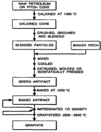
Having established that carbon (in the form of graphite) is an acceptable nuclear moderator, it is appropriate to briefly describe the process by which graphite is manufactured. Detailed accounts of the manufacture of polygrandar gmphite have been published elsewhere [2-51. The major processing steps in the manufacture of a conventional polygrandar graphite are summarized in Fig. 1. Polygranular graphite consists of two phases: a filler material and a binder phase. The predominant filler material, particularly in the U.S.A, is a petroleum coke made by the delayed coking process. European nuclear graphites are typically made from a coal-tar pitch-derived coke. In the U.K., a Gilsonite coke derived from a naturally occurring bitumen found in Utah, U.S.A., has been used. The coke is usually calcined (thermally processed) at -1300°C prior to being crushed and blended. Typically, the binder phase is a coal-tar pitch. The binder plasticizes the filler coke particles so that they can be formed. Commonly used forming processes include extrusion, molding, and isostatic pressing. The binder phase is carbonized during the subsequent baking operation (- 1000°C). Frequently, engineering graphites are pitch impregnated to densify the carbon artifact, followed by rebaking. Useful increases in density and strength are obtained with up to six impregnations, but two or three are more typical.
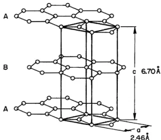
The r i a l stage of the manufacturing process is graphitization (2500-3000°C) during which, in simplistic terms, carbon atoms in the baked material migrate to form the thermodynamically more stable graphite lattice. Nuclear graphites require high chemical purity to minimize neutron absorption. Moreover, certain elements catalyze the oxidation of graphite and must be reduced to an acceptable level. This is achieved by selecting very pure cokes, utilizing a high graphitization temperature (>2800"c), or by including a halogen purification stage in the manufacture of the cokes or graphite. In its perfect form, the crystal structure of graphite (Fig. 2) consists of tightly-bonded (covalent) sheets of carbon atoms in a hexagonal lattice network [6]. The sheets are weakly bound with van der Waals type bonds in an ABAB stacking sequence with a separation of 0.335 nm. The crystals in a manufactured, polygranular graphite are less than perfect, with approximately one layer plane in every six constituting a stacking fault. The graphite crystals have two distinct dimensions, the crystallite size La measured parallel to the basal plane
434
and the dimension L, measured perpendicular to the basal planes. In a coke-based nuclear graphite, values of La
-
80 nm and L,-
60 nm are typical [7].CALCWED COKE
'
CRUSHED, (AOUNED AND WENDEDEXTRUDED. MOLDED OR ISOSTATICALLY PRESSED OREEN ARTIFACT
BAKED A T ioDD .C BAKED ARTIFACT
IMPREQNATED TO DENSIFY GRAPHITKED 25GQ-2800%
Fig. 1. The major processing steps in the production of a conventional polygranular graphite.
Fig. 2. The crystal structure of graphite.
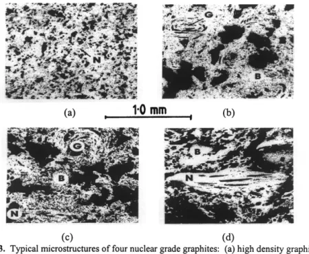
Typical nuclear graphite microstructures are shown in Fig. 3. The Gilsonite filler coke used in IM1-24 graphite [Fig. 3(b)] is clearly visible. High density graphite (HDG) and pile grade A (PGA) graphites, (a) and (d) in Fig. 3 respectively, contain a needle coke filler, which takes its name from the acicular pores in the coke. The size of the needle coke particle is markedly different in the two graphites, as is the general structure of the material. Graphite (c) in Fig. 3 (grade SM2-24) has a mixture of needle and Gilso-coke fillers. As discussed by Heintz [8], the coke structure can have a major influence on the properties of a graphite artifact.
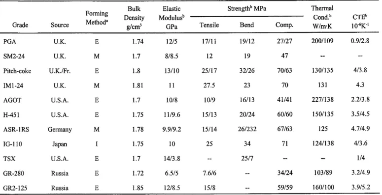
Indeed, by careful selection and preparation of the coke, and forming method, it is possible to produce an isotropic graphite. Another striking difference in the structure of the graphites in Fig. 3 is the size and shape of the pores within the graphite. The pore structure has a significant effect on the behavior of a nuclear graphite during service. First, it provides accommodation for irradiation-induced crystal strain (see later discussion). Second, the pores transport the reactor coolant gas into the graphite where it (or the impurities in the coolant gas) may react and gasify the graphite (see later discussion of radiolytic oxidation). Finally, the pore structure controls the fracture behavior of a graphite [9,10]. The properties of some common nuclear grade graphites are given in Table 4.
(c) ( 4
Fig. 3. Typical microstructures of four nuclear grade graphites: (a) high density graphite (HDG); (b) M1-24, a Gilsonite coke graphite; (c) SM2-24, a Gilsonite and needle coke containing graphite; and (d) pile grade A (PGA), a needle coke graphite. In the figure G denotes Gilsonite filler coke, N denotes petroleum (needle) filler coke, and B denotes binder graphite.
Table 4. Physical and mechanical properties of some common nuclear graphites[l l-191
i5
Q\Strengthb MPa Thermal
Bulk Elastic
Density Modulusb Cond? CTEb
Grade Source Method" glcm' GPa Tensile Bend Comp. WlmK 1 OdK-'
Forming
PGA U.K. E 1.74 1215 1711 1 19/12 27127 2001109 0.912.8
__
--SM2-24 U.K. M 1.7 818.5 12 19 47
Pitch-coke U.K./Fr. E 1.8 13/10 25117 32/26 70163 1 301 1 35 413.8
IM 1 -24 U.K. M 1.81 11 27.5 23 70 131 4.3
AGOT U.S.A. E 1.7 1018 1019 16113 41/41 2271138 2.213.8
H-45 1 U.S.A. E 1.75 1119.6 15/13 20124 60160 1501135 3.514.5
ASR- 1 RS Germany M 1.78 9.919.2 15/14 261232 67163 125 4.714.9
IG-110 Jzlpm I 1.75 10 25 34 71 12411 3 8 413.6
TSX U.S.A. E 1.7 1413.8 -- 2517 --
__
1 I4GR-280 Russia E I .72 6.515 7.616 -- 34124 103189 3.214.9
GR2- 125 Russia E 1.85 1218.5 1518 -- 59159 1601100 3.915.2
aE-extruded, M-molded, I-isostatic pressing; to the forming axis
1.4 Historical use of graphite as a nuclear moderator
Graphite has been used as a nuclear moderator for over 50 years. The earliest reactors were comprised of stacks or “piles” of graphite blocks. In 1942, when a group of scientists led by Enrico Fermi [20] attempted to produce a self-sustaining nuclear chain reaction, graphite was chosen as the moderator because it was the only suitable material available. This fist nuclear pile, designated CP-1, was constructed on a squash court under the stands of Stagg Field at the University of Chicago, and contained some 385.5 tons of graphite, the vast majority being grade AGOT manufactured by the National Carbon Company [20]. The world’s fist nuclear chain reaction was produced in CP-1 on December 2, 1942. The design of Fermi’s reactor was based on data obtained from his earlier experiments at Columbia University aimed at determining the multiplication factor (k), the ratio of the number of neutrons in any one generation to the number of neutrons in the previous generation [21]. A sustained nuclear chain reaction will occur when k >
1. By the time CP-1 was being constructed in the spring of 1942, the value of k,
= 1.007 had been estimated for a uranium metal-graphite pile with sufficient accuracy to make a chain reaction in an infinite system a practical certainty [22].
However, control of the reaction, once initiated, was subject to considerable uncertainty.
CP-1 was assembled in an approximately spherical shape with the purest graphite in the center. About 6 tons of uranium metal fuel was used, in addition to approximately 40.5 tons of uranium oxide fuel. The lowest point of the reactor rested on the floor and the periphery was supported on a wooden structure. The whole pile was surrounded by a tent of rubberized balloon fabric so that neutron absorbing air could be evacuated. About 75 layers of 10.48-cm (4.125-in.) graphte bricks would have been required to complete the -790-cm diameter sphere.
However, criticality was achieved at layer 56 without the need to evacuate the air, and assembly was discontinued at layer 57. The core then had an ellipsoidal cross section, with a polar ra&us of 209 cm and an equatorial radius of 309 cm [20]. CP- 1 was operated at low power (0.5 W) for several days. Fortuitously, it was found that the nuclear chain reaction could be controlled with cadmium strips which were inserted into the reactor to absorb neutrons and hence reduce the value of k to considerably less than 1. The pile was then disassembled and rebuilt at what is now the site of Argonne National Laboratory, U.S.A, with a concrete biological shield.
Designated CP-2, the pile eventually reached a power level of 100 kW [22].
43 8
In early 1943, construction began on the X-10 reactor at what is now the Oak Ridge National Laboratory, U.S.A. The air-cooled X-10 reactor contained some 400 tons of moderator graphite, 274 tons of reflector graphite, and was rated at 3.5 MW(t).
Criticality was achieved in November 1943 [22]. Also, construction commenced on the fist reactors at the Hanford (U.S.A.) site in 1943. The mission of the Oak Ridge and Hanford reactors was the production of weapons grade U and Pu under the auspices of the U.S. Government's Manhattan Project. It is worth noting that the first irradiated fuel was discharged from the Hanford B reactor less than two years after the historic demonstration of a self-sustaining nuclear reaction in CP- 1 [23]. The early Hanford reactors [23] were designed to operate at 250MW(t), significantly higher than the X-10 reactor. They had a core volume of 654 m3 and contained 1200 tons of moderator graphite and 600 tons of reflector graphite [22].
The reactors were surrounded by a CO,/He gas mixture and were water cooled. In the U.K., two graphite moderated research reactors, the Graphite Low Energy Experimental Pile (GLEEP) and the British Experimental Pile Zero (BEPO), were built at Harwell. BEPO was rated at 6.5 MW(t), contained 310 tons of moderator graphite and 540 tons of reflector graphite, and was air cooled. BEPO went critical in July 1948 [22]. The construction of two graphte moderated production reactors at Windscale U.K. followed. The reactors were rated at 160 MW, were air cooled and went critical in 1950 and 1951. Both Windscale reactors were shutdown in 1957 [24]. Similar developments occurred in France, with the G1 reactor (criticality achieved January 1956), and in the U.S.S.R. [22].
2 Graphite Moderated Power Producing Reactors
A variety of graphite moderated reactor concepts have evolved since the first air- cooled reactors of the 1940s. Reactors with gas, water, and molten salt coolants have been constructed and a variety of fuels, and fissile/fertile fuel mixtures, have been used. The evolution and essential features of graphite moderated power producing reactors are described here, and details of their graphites cores are given.
2. I Gas-cooled reactors 2.1.1 Magnox reactor (U.K.)
The Magnox reactor concept owes its origins to a design study conducted at Harwell, U.K., during the early 1950s. The reactor was designed with the dual role of plutonium and power production, and was known by the code word PIPPA
(pressurized pile producing power and plutonium) [26]. The inherently stable graphite-moderated gas-cooled reactor concept was adopted over the water-cooled, graphite-moderated design, which was used for the Hanford, U.S.A, reactors, because of the lack of remote sites in the densely populated U.K. [27]. Early in the design it was decided that the reactor would be fueled with natural-uranium, and thus the moderator had to be either graphite or heavy water. The latter option was dismissed on the basis of cost. Wasteful neutron capture occurs in the graphite, coolant gas, and fuel cladding. Therefore, considerable effort was expended in selecting appropriate materials for the PIPPA design. The moderator graphite, Pile Grade A (PGA), was manufactured from a particularly pure coke, thus reducing its neutron capture cross section substantially relative to the graphites used in earlier experimental reactors such as BEPO.
The choice of fuel canning materials was limited to those with low capture cross section, such as beryllium, magnesium, aluminum, and zirconium. Beryllium was hard to obtain, difficult to fabricate, and is highly toxic. Zirconium was impossible to obtain in the hafnium-free state essential for reactor applications.
Therefore, only aluminum and magnesium were considered viable. Magnesium, at the time of the PIPPA design study, had not been used in reactor applicabons because its low neutron capture cross section only became known in 1948 [26].
One significant advantage that magnesium has over aluminum is its lack of reaction with the uranium fuel. After careful metallurgical investigation of various magnesium alloys, a Mg-Q.S%Al-Q.Ol%Be alloy which exhibited low oxidation was selected [28]. The use of this alloy for the fuel cladding led to the eventual adoption of the reactors familiar Mugaox name ( w n e s i u m non-midizing).
The need to keep neutron absorbing metal out of the core led the designers away from the use of liquid metal coolant, or water coolant running through the core in metallic tubes. A gas chemically compatible with graphite, enabling it to flow directly through the moderator, thus appeared to be the only option. A study of potential cooling gases for PIPPA concluded that helium would be the most suitable gas because of its excellent heat transfer properties and chemical inertness.
However, helium was unavailable in the U.K. in sufficient quantities, and import from the U.S.A. was restricted by the MacMahon Act. Other potential gases were rejected because of chemical incompatibility with graphite and metals, excessive neutron absorption, poor stability under irradiation, induced radioactivity, or poor heat transfer characteristics. Carbon dioxide emerged as the inevitable compromise. Although CO, is somewhat inferior to helium as a coolant, it had the
440
advantage of being plentiful, inexpensive, commercially pure, and easy to handle.
Initial concerns that the reaction of CO, and graphite in the presence of radiation (Radiolytic Oxidation-Section 4) would be excessive were proved to be unfounded, and this cleared the way for the detailed design of a CO, cooled, graphite- moderated reactor.
In designing the graphite core several requirements had to be met. Stability and alignment had to be preserved in the core; the shape and linearity of the fuel and control rod channels had to be maintaind, fracture of the graphite at the channel wall had to be avoided; irradiation-induced dimensional changes within each block, and across the core, could not adversely effect the safety or performance of the core; the graphite blocks had to possess sufficient strength to not fail under thermally induced stresses; transient and steady state temperature gradients across the blocks could not cause instability; coolant leakage from the fuel channels had to be minimized; neutron streaming and leakage from the core had to be minimized; and the core had to be economic in its use of graphite.
Prior to the PIPPA design study all of the graphite reactors built had the axis of the he1 and core horizontal. This concept was rejected for the PIPPA because support of the heavy graphite core from the surface of the pressure vessel proved to be an intractable problem [26]. While a vertical arrangement complicated the insertion, support, and removal of the uranium fuel elements, it allowed for a fail-safe gravity feed control rodreactor shutdown system. Therefore, a vertical axis graphite pile was adopted, built up from individually machined blocks to produce a 24-sided prism about 36 ft (10.97 m) across, with a height of about 27 ft (8.23 m). The core consisted of some 32,000 graphite blocks each weighing about 100 Ibs (45.4 kg) and measuring 25 in. (63.5 cm) in length and about 8 in. (20.3 cm) square. The core mass of about 1454 tonnes was supported on a steel grid framework about 4 ft (I .22 m) thick. The thermal expansion mismatch between the steel grid and the graphite core was accommodated by supporting the graphite on small steel rollers.
Radial keyways located the stack in the pressure vessel.
By the end of 1952 it was certain that a PIPPA design had been produced which could and should be built. A summary report was prepared in January 1953, and soon after approval was granted for construction of the first two Magnox reactors at Calder Hall. Before the first reactor went critical in 1956 work had started on a further two reactors at Calder Hall, and all four were at power in 1959.
Construction at Chapelcross, in the southwest of Scotland, began in 1955. The fist
reactor was at power in 1959 and all four at Chapelcross were in operation by early 1960. The first eight Mugnox reactors were, therefore, designed, constructed, and commissioned within nine years. The construction of the eight dual-purpose Mugnox reactors was followed by an expanded civil construction program in the U.K. and overseas (Latina, Italy and Tokai, Japan). Moreover, conceptually similar reactors were built in France (G2/G3, Chinon Al, A2 & A3, St. Laurent A1 & A2, and Bugey) and Spain (Vandellos) [29].
A total of nine commercial twin Magnox reactorlpower plants were built in the U.K. (Table 5), culminating with the Wylfa reactors which began operation in 197 1. The Mugnox reactors at Wylfa each have a graphite core with a diameter of 18.7 m, a height of 10.3 m, amass of 3740 tonnes, and contain 6150 fuel channels.
Wylfa's net electrical output is 840 MW from two 1600 MW(t) reactors, substantially larger than the 150 MW(t) reactor with an electrical output of 35MW envisaged in the PIPPA design study! Table 6 shows key reactor parameters for several of the U.K. Magnox reactors, and illustrates the evolution of the Magnox reactor design.
Table 5. Commercial Magnox power plants in the U.K. [29]
Commissioning Coolant Reactor Ratingb
Location Date Pressure (MPa) Vessela Frw(e>I
Berkeley Bradwell Hunterston A Hinkley A Trawsfynydd Dungeness A Sizewell A Qldbury Wylfa
1962 1962 1964 1965 1965 1965 1966 1968 1971
0.9 0.9 1
.o
1.3 1.6 1.8 1.9 2.4 2.7
Steel(c) Steel( s) Steel(s) Steel(s) Steel(s) Steel(s) Steel(s) Concrete(c) Concrete(c)
276 245 300 43 0 390 410 420 416 840
a (c) = cylindrical, (s) = spherical.
'
Continuous maximum, net h m two reactorsTable 6. Key parameters of several U.K. Magnox reactors [30]
Reactors
Calder TEIWS-
Parameters Units Hall Berkeley fjmydd Wylfa
General Output net No. of reactors Heat outputheactor Inlet gas temp.
Outlet gas temp.
Net thermal effic.
(1979/80) Pressure vessel Material Geometry Steel thickness Internal diameter Internal height Working pressure Graphite moderator Active core diameter Active core hieght Specific power Diameter over flats Overall height Overall weight No. of fuel channels Lattice pitch Max thermal flux Fuel
Weight of U/reactor Specific power Mean irradiation Turbo-alternators No. per station Capacity
output gross MWe
Mwe MWth
"C
"C
mm m m bar
m m MW/m'
m m m mm dCm/S
t kWkg MWD/t
MW
240 4 272
150 345
steel cylindrical
51 11.28 21.24 6.8 9.45 6.4 0.61 10.97
8.23 1158 1696 203 --
111 2.4 3500
8 30
276 334.4
2 167 350 21.83
--
steel cylindrical
76.102 15.2 24.2 9.6 13.1
7.4 14.6 9.1 1938 3265 203 1 . 7 ~ 1 013
--
23 1.45 2.4 4300
4 83
390 840
474.8 1001.6
2 2
860 1600
180 23 0
360 360
24.34 25.78
steel concrete spherical spherical 89.0 19.5 18.3 29.3 17.6 27.0
__ - -
13.7 17.4
7.9 9.1
0.76 0.74 14.6 18.7 8.3 10.3 1900 3740 3740 6150
197 197
2x10'3 2.0~1013
280 595
3.1 1 3.16 4300 4755
4 4
145 247.5
2.1.2 Advanced gas-cooled reactor, AGR (U.K.)
The large physical size of the later Mugnox stations, such as Wylfa, led to the development of the more compact advanced gas-cooled reactor (AGR) design [3 11 that could utilize the standard turbine generator units available in the UK.
Stainless-steel clad, enriched uranium oxide fuel can tolerate h g h e r temperatures
than Magnox fuel, allowing higher coolant outlet temperatures in the AGRs. Llke the Magnox reactors, the AGR has a graphite core and utilizes carbon dioxide gas coolant. The entire core, the boilers, and the gas circulators are enclosed in a prestressed concrete vessel. A typical AGR station in the U.K. [3 11 has twin 660 MW(e) nominal reactors with the major performance parameters listed in Table 7.
Initial experience and confirmation of the operating characteristics of the AGR were gained fromthe 30 MW(e) prototype AGR at Windscale, U.K. (WAGR) [32].
Seven AGR stations have been constructed in the U.K.- Dungeness B, Hartlepol, Heysham I&II, Hunterston B, Hinkley Point B, and Torness.
Table 7. The major performance parameters of a typical AGR (Heysharn II and Torness design) [33]
Parameter Value
Reactor heat 1550 MW(t)
Number of fuel channels 332
Mean fuel channel power 4.7 MW(t)
Mean fuel channel outlet temperature 635°C
Gas circulator total flow 4271 kg/s
Gas circulator pressure rise 0.2896 MPa
Gas circulator power consumption per reactor 42.6 MW(e) Gas circulator outlet gas pressure 4.36 MPa abs
Steam generator steam flow 500 kg/s
Steam pressure at turbine inlet 16 MPa abs
Steam temperature at turbine inlet 53 8°C
Steam generator feedwater temperature 156°C
Circulator gas outlet temperature 229°C
The AGR reactor core is a six-sided prism of stacked graphite bricks connected at the periphery to a steel restraint tank. Integral graphite and steel shelds are incorporated into the graphite structure above, below, and surrounding the active core, thus reducing radiation levels and making it possible for personnel to enter the pressure vessel. The graphite moderator bricks are penetrated from the bottom to the top of the core by 332 channels containing fuel stringers. Interstitial channels, interspersed amongst the fuel channels, contain the control rods. Figure 4 shows the graphite moderator bricks from a typical AGR core (Hinkley Point B) under construction. The control rods consist of axially-linked, articulating tubular sections that contain boron-doped stainless steel. The graphite fuel bricks are additionally penetrated by axial holes which allow access of methane to the inner portions of the graphite brick. The methane is added to the carbon dioxide coolant as a radiolytic corrosion inhibitor (see Section 4).
444
Fig. 4. A typical advanced gas-cooled reactor graphite core (Hinkley Point B under construction) [I 11.
The graphite core is located within a steel envelope called the gas baffle, which provides for reentrant cooling of the graphite structure (Fig. 5). Cooled carbon dioxide is drawn from the bottom of the steam generators by the gas circulators and discharged into the plenum below the core inside the gas baffle. About 30% of the gas flows directly into the fuel channel inlets, while the remainder (reentrant flow) passes up the annulus surrounding the core, returns down through the core in passages between the outer graphite sleeves of the fuel element assemblies and the graphite core bricks to the fuel channel inlets at the bottom of the core, were it combines with the cool gas flowing directly from the circulators (Fig. 5). The purpose of the reentrant flow is to cool the moderator bricks and the core restraint system. The gas baffle serves to contain the reentrant flow and isolate it from the fuel channel hot outlet flow. The hot gas passes up through the plenum above the graphite core in guide tubes which penetrate the thermally insulated top of the gas baffle, and then flows to the top of the steam generators. The entire core structure sits on a support grid (diagrid) which is itself supported by the skirt that forms the lower end of the gas baffle cylinder. The skirt is welded to the pressure vessel liner and includes an anchorage arrangement that ensures structural loads are transmitted to the concrete foundation of the pressure vessel bottom slab.
Fig. 5. The gas flow path of an AGR Note the flow is reentrant, i.e., a fraction of the cool gas from the circulator flows up around the outside of the core entering the core from the top, then flows downward through the core, between the moderator and fuel element assembly, to the bottom where it mixes with the cool gas from the circulator and flows up the fuel channel inside the graphite fuel sleeves to the steam generators. Reprinted from [33], 0 1977 Wilmington Business Publishing, Dartford, U.K., with permission.
Four steam generators, each consisting of three separate factory assembled units, are positioned in the annulus between the gas baffle and the inner wall of the pressure vessel. After passing down through a steam generator, the cooled carbon dioxide gas discharges into one of the quadrants of the circulator annulus which forms the entry plenum for eight 5.2 MW gas circulators mounted horizontally through the vessel side wall. This plenum is isolated from the boiler annulus by the main gas seal and is divided into four quadrants by division plates so as to form four reactor cooling circuits, each comprising one steam generator and two gas circulators in parallel. The steam generators supply two 660 MW(e) nominal turbines.
446
The fuel assembly consists of a fuel stringer and a fuel plug unit. The fuel stringer is comprised of eight 36-pin fuel elements stacked one above the other and suspended from the fuel plug unit by a tie bar. The fuel pins consist of enriched uranium oxide pellets clad in stainless steel and supported in steel grids mounted in a graphite sleeve. The fuel plug unit controls the coolant flow through the fuel stringer and also forms the shield and seal for the standpipe through which the fuel stringer is loaded into the reactor.
Several grades of graphite are used in the AGRs. The core bricks (Fig. 4) are machined from the isotropic nuclear grade IM1-24 (Section 1.3). Isotropy is achieved in Ih41-24 graphite by utilizing the spherical Gilsonite coke and a molding process to form the graphite. The result is a moderator graphite with more than twice the strength of its predecessor, PGA. Moreover, the isotropic behavior of the graphite has significant advantages with respect to its response to radiation damage. The reflector region of the AGR core contains grade SM2-24, a molded graphite made from a blend of needle coke and Gilsonite coke filler. The AGR fuel sleeves are made from pitch-coke graphite, which is produced from coal-tar pitch- derived coke and formed by extrusion.
2.1.3 Dragon Reactor Experiment, DRE (Euratom)
The High Temperature Reactor Project, or Dragon Reactor Experiment @RE) as it was more commonly known (located at Winfrith, Dorset, U.K.), went critical on August 23, 1964 [34]. Dragon was an experimental 20 MW(t) reactor with helium coolant at a working pressure of 2 MPa and an outlet temperature of -750"C, significantly hotter than the AGR coolant outlet temperature of 630°C. Although the DRE was not a power producing plant, its status as a first-of-its-kind high- temperature gas-cooled reactor (HTGR) makes it worthy of inclusion here. The DRE's mild steel pressure vessel was 17.8 m high with a maximum diameter of 3.4 m 11291. A reentrant jacketed coolant flow arrangement maintained the walls of the vessel and heat exchangerlcirculator branches at their optimum temperature of -300°C. The helium flowed upwards through the core, entering at 370"C, and emerging at an average temperature of 810-830°C. A fraction of the total primary coolant flow, varying between 15 and 25%, bypassed the core and, therefore, the gas temperature at the primary heat exchangers was somewhat lower, typically 720°C.
The DRE core assembly consisted of 37 fuel elements 2.4 m in length, each comprised of a cluster of seven hexagonal section rods with ribs to separate them and provide a space for coolant flow. The central core section of each rod (1.4 m length) consisted of a graphite tube surrounding a stack of annular fuel compacts with a central graphite spine. The rod clusters were eventually replaced with a block type fuel element which was more representative of the core structures proposed for high temperature power reactors [34]. The radial graphite reflector
consisted of a fixed outer region of rigidly stacked blocks and two inner rings of vertical pillars which pivoted on a base plate. The thu-ty inner pillars were penetrated by channels, 24 of which served as control rod ducts. These inner columns were replaceable by means of the charge machine. The high neutron flow into the reflector, and the small core volume (1.4 m3), allowed the reactor to be controlled by absorbers outside the core-reflector interface. The DRE was fueled with 93% enriched uranium [34] and a fissile/fertile fuel mix. The latter was employed in only 10 of the 37 elements because of the heavy neutron loss. Initially the fertile component was thorium, but later u8U was utilized [29].
The Dragon reactor represented a departure from previous designs in that it did not have metallic clad fuel. Rather, a coated ceramic fuel bound in a carbon matrix (see Section 5) was clad in an entirely graphite structure. The initial Dragon design called for a fully emitting fuel from which the gaseous fBsion products freely escaped. The fuel design was changed to the fission product retaining coated particle type in May 1963. However, considerable effort had been expended on the development of low-permeability nuclear graphites as a consequence of the earlier fuel design. The gaseous fission products were to be purged from the fuel by a helium purge passing over the annular fuel bodies, through a location spike on which the fuel elements rested, to the fission product cleanup system. The purge flow was reduced to an acceptable level by using a low permeability fme-grained graphite. The selected graphite (Morganite Carbon Limited, grade EY-9) had to be subjected to additional processing to reduce its permeability to an acceptable level. This process, developed by the Royal Aircraft Establishment, Farnborough, U.K. [35], involved impregnation of the porous carbon with fbrfuryl alcohol, or a furan derivative to which a suitable polymerization catalyst had been added. The impregnant resin was cured in situ and pyrolyzed to 1QQQ"C to leave a carbon deposit in the pore network. T h s process was carried out repetitively until the permeability was sufficiently reduced. Attaining grade EY-9 at nuclear purity proved to be problematic because the graplvte picked up excessive boron during graphitization at the Morganite plant. Eventually, the material was purchased from Morganite in the baked stage and shipped to Compagnie Pechiney, France, fox combined purification and graphitization at 2700°C. The graphite was then returned to the U.K. for impregnation, regraphitization, and outgassing at Winfrith.
The switch to coated particle fuel and the realization that the high temperature (>900°C) irradiation stabihty of EY-9 was unacceptable (EY-9 contained a signifcant portion of small crystallites due to the carbon black filler used), caused a change in the Dragon graphite development program away from fine-grained materials to coarser isotropic and near-isotropic graphites [34].
2.1.4 Peach Bottom (U.S.A.)
The HTGR designed by the General Atomic Company and constructed at Peach Bottom, Pennsylvania, U.S.A., was a 40 MW(e) experimental power plant which was similar in many respects to the Dragon reactor. Peach Bottom started commercial operation on June 1,1967, and ceased operation on October 31,1974 [36]. The major performance parameters of the Peach Bottom Reactor are shown in Table 8.
Table 8. The major performance parameters of the Peach Bottom Reactor [29]
Parameter Value
Coolant Pressure
Core inlet temperature Core outlet temperature Steam temperature
Steam pressure Net thermal efficiency Reactor thermal output Net electrical power Pressure vessel
Diameter Height
Effective Diameter Active height Specific power Fuel element diameter Fuel element length Number of fuel elements Reflector thickness Normal operating-rods Shut-down rods Core
Control rods Fuel life at full power
Helium 2.4 MPa 344°C 728°C 538°C 10.00 MPa
34.6%
115 MW(t) 40 MW(e)
4.3 m 10.8 m
2.8 m 2.3 m 8.1 MWIm’
8.9 cm 366 cm 804 61 cm
36 19 900 days
The fuel for the Peach Bottom reactor consisted of a uranium-thorium dicarbide kernel, overcoated with pyrolyhc carbon and silicon carbide which were dispersed in carbon compacts (see Section 5), and encased in graphite sleeves [37]. There were 804 fuel elements oriented vertically in the reactor core. Helium coolant flowed upward through the tricusp-shaped coolant channels between the fuel elements. A small helium purge stream was diverted through the top of each element and flowed downward through the element to purge any fission products leaking from the fuel compacts to the helium purification system. The Peach
Bottom 1 prototype HTGR operated successfully in all respects under the auspices of the US. Atomic Energy Commission’s Power Reactor Demonstration Program.
However, its size (only 40 MW) was insufficient to justify continued commercial operation.
2.1.5 Fort St. Vrain (U.S.A.)
The 330 W ( e ) Fort St-Vrain Nuclear Generating Station was the first commercial-size HTGR to employ the multihole fuel block design developed by Gulf General Atomic in the U.S.A. [38]. The construction permit for the plant was received in September 1968 [39] and construction was essentially complete in August 1971 [38], with initial criticality being attained on January 31, 1974. The major performance parameters of Fort St. Vrain are given in Table 9. The fuel was of the Triso particle type (see Section 5 ) with kernels of fissile uranium dicarbide (93% enriched) or fertile thorium dicarbide [40].
TabIe 9. The major performance parameters of the Fort St. Vrain HTGR [29,38-401
Parameter Value
Coolant
Pressure
Core inlet temperature Core outlet temperature Steam temperature
Steam pressure Net thermal efficiency Reactor thermal output Net electrical power
Concrete pressure vessel cavity Diameter
Height
Effective Diameter Active height Specific power
Fuel element (distance across flats) Fuel element length
Number of fuel elements Number of fuel columns Reflector thickness (average) Number of reheling regions Control rods
Normal operating-rods B,C Reserve shut-down channels Core
Fuel life at full power
Helium 4.83 MPa
4OOOC 77OOC 538°C 16.5 MPa
38.5%
842 MW(t) 330 MW(e) 9.45 m 22.9 m 5.94 m 4.75 m 6.4 MWfm3
36.07 cm 78.74 cm 1482
247 118.9 cm
37 37 (pairs)
37 6 years
450
The reactor core was made up of stacks of hexagonal graphite blocks. Each fuel element block had 210 axial fuel holes and 108 axial coolant holes (Section 5, Fig.
14). The fuel particles were formed into a fuel compact (Section 5.3) and sealed into the fuel channels.
The core was divided into 37 regions, each containing 7 columns, except for the 6 regions at the core periphery which each contained 5 columns. The center column fuel elements and top reflector additionally contained three control rod channels, two for the operational rods and one for the B,C reserve shutdown material. Each fuel region was centered beneath a reheling penetration in the prestressed concrete pressure vessel. During operation each of the penetrations contained a control rod drive and a controllable orificing assembly to control coolant flow. The coolant gas exited the bottom of the steam generators at 400°C and flowed around the core in the anndus between the inner surface of the concrete vessel's steel liner and the metallic core barrel. It entered the core from the top and flowed down through the fuel elements, mixing in the plenum beneath the bottom reflector before it entered the top of the steam generators at 770°C.
A conventional extruded needle-coke nuclear graphite, grade H-327, was selected for the fuel elements. Later, the fuel element graphite was changed to H-451, a near isotropic grade (Table 4). The radial reflector was composed of two parts.
Immediately surrounding the core were replaceable reflector elements which were essentially identical to the fuel elements. The reflector elements were arranged in columns, but did not contain coolant or fuel channels. The reflector elements, along with those on the top and bottom of the core, were replaced when their associated fuel region was replaced. The second part of the r a d d reflector was the large permanent graphite blocks of irregular shape that surrounded the replaceable reflector and transitioned the hexagonal core brick shape to the cylindrical core barrel. The permanent reflectors were machined from grade PGX graphite.
The Fort St. Vrain HTGR was permanently shutdown in August 1988 [41]. The nuclear island performed well during the reactors 15-year life, although significant problems were encountered with some of the reactors non-nuclear support systems
[29,38].
2.1.6 The AVR and THTR-300 (Germany)
The Arbeitsgemeinschaft Versuchsreaktor (AVR) and Thorim High-Temperature Reactor (THTR-300) were both helium-cooled reactors of the pebble-bed design [29,42,43]. The major design parameters of the AVR and THTR are shown in Table 10. Construction started on the AVR in 1961 and full power operation at I5MW(e) commenced in May 1967. The core of the AVR consisted of approximately 100,000 spherical pebble type fuel elements (see Section 5). The pebble bed was surrounded by a cylindrical graphite reflector and structural carbon
jacket [44]. The core bottom was conically shaped so as to funnel the fuel elements to the 0.5-m diameter pipe through which the fuel elements were discharged. The fuel elements were continuously added to the reactor core during reactor operation via five refueling pipes, passed through the core in about six months, and then entered the fuel element discharge pipe. Outside of the reactor the fuel elements were evaluated for their fuel burn-up and were either returned to defined regions of the core, or were removed for storage and reprocessing. Each element passed through the core, on average, ten times. Four graphite columns protruded into the reactor core, each containing a longitudinal bore hole for a shutdown control rod.
For normal control the AVR made use of the negative temperature coefficient of reactivity, which allowed power level control exclusively by coolant gas flow rate variations. The helium coolant flowed upwards through the core and was heated from 275°C to 950"C, exiting through slits in the top reflector to the steam generator located above the core. The AVR reflector was constructed from grade AN2-500 graphite.
Table 10. The major design parameters of the AVR and THTR-300 [29]
Reactors
Parameters units AVR THTR
Net power output W ( e ) 15 300
Thermal power MW 46 750
Mean power density MW/m3 2.6 6.0
Core height m 2.47 6.0
Core diameter m 3 5.6
Number of fuel elements 98000 675000
Absorber rods
Helium pressure MPa 1.09 3.9
In-core 0 42
In-reflector 4 36
No. of steam generators I 6
Helium inlet temperature "C 950 750
Superheated steam temperature "C 505 5501535 Pressure vessel
Material Steel Prestressed
concrete
Outer diameter m 5.8 24.8
External height m 24.9 25.5
Construction of the THTR-300 began in 1972. Completion of construction was originally expected in 1977, but first criticality was not achieved until September 13, 1983 [29]. Nuclear trials continued until May 31, 1987, and power operation started with handover of the plant on June 1, 1987 [43]. The reactor was shut down
452
in mid 1989, predominantly for political reasons [45]. Unlike the AVR, the THTR had a prestressed concrete pressure vessel. The reactor core consisted of a bed of 675,000 spherical graphite fuel elements each containing almost 1 g of uranium at 93% enrichment, and 10.2 g of thorium-232. The fuel elements were contained in a cylindrical graphite vessel approximately 6 m in height and 5.6 m in diameter.
The graphite vessel served as the neutron reflector. The bottom graphite reflector was conically shaped and tapered down to a central fuel element discharge pipe 80 cm in diameter. Reactor operating control and shutdown was achieved with 42 in- core rods which were inserted into the pebble bed, and 36 reflector rods which could be freely moved inside reflector control rod channels. Six electrically driven coolant gas blowers forced the helium to flow downward through the reactor core, where it was heated to 750°C by the spherical fuel elements. The coolant gas entered the hot plenum below the reactor core through holes in the bottom reflector and was then directed to the six steam generators via hot gas ducts. The helium exited the steam generators at 250°C and was redirected to the reactor core by the blowers. The fuel element h d l i n g system allowed continuous charging and discharging of the fuel. After discharge the fuel elements were automatically inspected for damage and those with unacceptable shape or dimensions were rejected. The elements were assessed for fuel burn-up and a process computer determined whether they were discharged or returned to the reactor core. The continuous refueling process assured that a uniform high burn-up was attained.
The nuclear graphites used in the THTR-300 core [46] were manufactured by Compagnie Pechiney, France. Grade P W N , a Gilsonite-coke graphite, was used for the core components close to the pebble-bed, including the bottom reflector ( f i t layer), core support blocks, fuel element outlet tubes, layers No. 11 to 36 of the core chamber wall, the lower layer of the core chamber ceiling, and for dowels and thermal insulation cartridges in the core chamber wall. Grade PAN, a peh-oleum-coke containing graphite, was used for the remainder of the core except for the bottom layer of the lower reflector, which was an ungraphitized version of grade PAN and served as a thermal insulator.
2.1.8 High Temperature Test Reactor, HTTR (Japan)
The HTTR is an experimental helium-cooled 30 MW(t) reactor. The HTTR is not designed for electrical power production, but its high temperature process heat capability makes it worthy of inclusion here. Construction started in March 1991 E471 and first criticality is expected in 1998 [48]. The prismatic graphite core of the HTTR is contained in a steel pressure vessel 13.3 m in height and 5.5 m in diameter. The reactor outlet coolant temperature is 850°C under normal rated operation and 950°C under high temperature test operation. The HTTR has a primary helium coolant loop with an intermediate helium-helium heat exchanger and a pressurized water cooler in parallel. The reactor is thus capable of providing
nuclear heat for process applications such as hydrogen production [48]. The principal design parameters of the HTTR are given in Table 1 1.
Table 11. The principal design parameters of the HTTR [47,48]
Parameter Value
Reactor thermal power 30 MW
Coolant
Type Helium gas
Outlet temperature 85O0C/950"C
Inlet temperature 395°C
Primary pressure 4 MPa
Dir. of coolant flow Downward-flow
Material Graphite
Height 2.9 m
Diameter 2.3 m
Average power density 2.5 W/cm3
Type Low enriched UO,
Element type Prismatic
Core
Fuel
Enrichment 3-10%
Average enrichment 6 Yo
Pressure vessel Material
Height 13.2 m
Diameter 5.5 m
Containment type Steel containment
No. of coolant loops 1
Plant lifetime 20 years
Steel (2 1/4 Cr-1 Mo)
The prismatic fuel elements are in the form of hexagonal blocks (similar to the Fort St. Vrain HTGR). The active core consists of 30 fuel element columns and 7 control rod guide columns. Each control rod column contains three control rod penetrations, and is surrounded by six fuel elements. The active core is surrounded by a replaceable reflector composed of a layer of hexagonal graphite blocks. The permanent reflector surrounds the replaceable reflector and consists of large irregular shaped blocks that are attached to the cylindrical presswe vessel. The fuel elements and replaceable reflectors are made from grade IG-110 graphite, and the permanent reflector blocks are made from grade PGX graphite. Reactivity control is provided by individually supported control rods which penetrate the hemispherical top head of the reactor pressure vessel and enter into the fueled region and replaceable reflector region. Hot shutdown is acbeved by insertion of the nine pairs of reflector control rods, followed by the seven pairs of control rods
454
in the fueled region when the core temperature is <900°C. Back-up shutdown capability is provided by boron carbide/graphite pellets that may be inserted into separate holes in the control rod guide blocks.
The fuel element is of the pin-in-block design and is 36 cm across the flats and 58 cm in height. The fuel consists of Triso coated particles of low enriched uranium oxide with a kernel diameter of 600 pn. The particles are bonded with a graphite powder to form the fie1 annular compacts, which are contained in graphite sleeves with a 3.4 cm outside diameter and thus form the fuel rod. The fuel rods are located in vertical holes of 4.1 cm diameter in the fuel element block. The helium coolant flows downward through the 3.5-mm annular gap surrounding each fuel rod in the fuel element. The fuel rods, fuel elements, and replaceable reflector blocks are made from the fine-grained, high-strength, isotropic grade IG-110 graphite (Table 4).
2.2 Water-cooled reactors 2.2.1 N-Reactor (U.S.A.)
The N-Reactor was the only reactor constructed at the Hanford, Washington site which produced both electrical power and special nuclear materials. The previous eight reactors were all non-power producing, material production reactors [23]. N- Reactor was a pressure-tubed, light water-cooled, graphite moderated reactor which produced 3800 MW(t) and 860 MW(e) [49]. The N-Reactor started up in June 1964 and ceased operations in January 1987 [23,49]. The design and operating parameters of the N-Reactor are reported in Table 12. The fuel tubes (containing enriched uranium fuel) ran horizontally through the reactor from front to back, while the core water coolant pipes (zirconium) ran horizontally through the core from side to side, perpendicular to the fuel tubes. Additionally, the control rods were mounted horizontally and ran into channels in the graphite core. There were a total of 87 water-cooled control rods, which had a scram speed of 76 Ws.
Reserve shutdown capability was provided by 108 vertical channels into which balls of absorber material could be dropped. Initially, the absorber balls were samarium oxide, but they were subsequently replaced with B,C.
The N-Reactor core was made up from a stack of interlocking grade TSX graphte blocks (Table 4). The core blocks had both keys and recesses machined into them such that when assembled an interconnected steam vent passage system running vertically and horizontally throughout the core was established. These passages gave sufficient cross-sectional area for steam and water dissipation to limit potential damage to a particular graphite block in which a tube burst might occur [49]. The active core was surrounded by a neutron reflector made from blocks of Speer nuclear grade 2 and Great Lakes Carbon nuclear grade 1 graphite, and was maintained under a low pressure, low flow, inert gas blanket. The entire core
assembly was contained within a steel thermal shield and a concrete biological shield, both of which were water cooled. The external dimensions of the reactor, including concrete biological shield, were 12 m in width, 14.55 m in depth, and 12.95 m in height [49].
Table 12. N-Reactor design and operating parameters [23,49]
Parameter Value
Power output, MW(e) 860
Thermal power, MW(t) 3800
Core
volume, m3 495
specific power, MWIm' 8.09 dimensions, m
pressure tubes (Zr-2) cooling tubes (Zr-2)
12.01 length, 10.06 width, 10.16 ht.
1003 installed (16.15 m length 640 installed side to side 6.86 cm ID, 8.26 cm OD)
(12.8 m len., 1.91 cm OD) Graphite
grade TSX
mass, tonnes 1800
number of blocks
reflector graphite 78,000 blocks; 17,000 sleeves Nuclear grade-2, grade R-1 operating temperature, "C 288
-
566Control system
normal operations emergency
87 water cooled, B,C hydraulically driven 108 vertical safety channels, B,C balls
9.53 mm OD.
2.2.2 RBMK (Russia)
There are currently 1 1 uranium-fueled, graphite-moderated, light water-cooled RBMK reactors operating in Russia [50]. The graphite is both the nuclear moderator and the major core structural component. The core of an RBMK reactor contains 2488 vertical channels formed by stacks of rectangular section graphite bricks with an axial hole (1 1.4 cm in diameter) to accommodate the channel tube.
There are 2044 fuel and control rods channels and 444 channels in the core periphery which are filled with graphite rods and act as the reflector [5 1,521. The entire graphite stack has a mass of approximately 1700 tonnes 11521. Key design parameters of the RBMK graphite core are shown in Table 13. Radial displacement of the graphite stack is restrained by 156 water-cooled supporting tubes situated in the core periphery. The cooling tubes are free to move in vertical guides in the upper structure of the containment, and are welded to the core support
45 6
structure at their base. The core is contained above and below by the biological shield, and is surrounded by a 10% nitrogen/90% helium blanket and a water tank.
Table 13. The key design parameters of the RBMK-1000 reactor and graphite core [5 1,521
Parameter Value
Reactor power, MW thermal electrical
Specific power, MW/m3 Configuration
Channel arrangement Number of channels
Graphite grade Dimensions
height, m diameter, m brick dimensions width, cm breadth, cm height, cm Core
Maximum graphite temperature, "C
3200 1000 2.67 Cylindrical Vertical 2488 GR-280 8 13.8 24.88 24.88 750 20-60
The core cavity environment is maintained below atmospheric pressure. Each of the core brick columns is independent from it neighbors (no radial keying) and a gap (-1 mm) exists between adjacent bricks to accommodate radial thermal expansion and radiation-induced swelling. A cup and cone arrangement is used to join the bricks vertically. The top and bottom of the column consist of steel bricks.
The bottom brick rests on a spigot, and the top of the column is aligned with the biological shield channel penetration by means of a telescopic joint. The brick to brick interfaces are staggered in adjacent channels to avoid horizontal planes of weakness. The fuel assembly is inserted in the channel tube hole in the center of each moderator column, and consists of a zirconium pressure tube into which the fuel element is inserted, and through which the water coolant flows. The fuel element assembly is removed before removing the pressure tube. The pressure tube is positioned in each moderator brick by a series of graphite split rings, which are alternately a close fit to the pressure pipe or the moderator brick fuel channel bore. Aligned slots in the graphite rings allows free flow of the gas blanket along the channels. Two types of graphite are used in the RBMK reactors. The moderator bricks are GR-280 grade graphite (Table 4) and the split rings are machined from grade GR2-125 graphite (Table 4). Both grades are anisotropic and have densities of 1.71 and 1.85 g/cm3, respectively [52].
![Table 1. Energy distribution from the fission of a UZ3' atom [I]](https://thumb-ap.123doks.com/thumbv2/123dok/11177289.0/1.748.128.613.722.849/table-1-energy-distribution-fission-uz3-atom-i.webp)
![Table 2. Scattering properties of some nuclei [l]](https://thumb-ap.123doks.com/thumbv2/123dok/11177289.0/3.748.130.621.695.872/table-2-scattering-properties-nuclei-l.webp)
![Table 3. Properties of good moderators [1]](https://thumb-ap.123doks.com/thumbv2/123dok/11177289.0/4.748.130.621.427.556/table-3-properties-good-moderators-1.webp)
![Table 5. Commercial Magnox power plants in the U.K. [29]](https://thumb-ap.123doks.com/thumbv2/123dok/11177289.0/13.748.132.623.500.710/table-commercial-magnox-power-plants-u-k-29.webp)
![Table 6. Key parameters of several U.K. Magnox reactors [30]](https://thumb-ap.123doks.com/thumbv2/123dok/11177289.0/14.748.137.622.136.771/table-key-parameters-u-k-magnox-reactors-30.webp)
![Table 7. The major performance parameters of a typical AGR (Heysharn II and Torness design) [33]](https://thumb-ap.123doks.com/thumbv2/123dok/11177289.0/15.748.139.621.331.589/table-major-performance-parameters-typical-heysharn-torness-design.webp)
