The publisher, authors and editors are confident in assuming that the advice and information in this book is believed to be true and correct at the date of publication. Plasma physics has grown so much that it's tempting to include everything that's new, but I haven't.
Occurrence of Plasmas in Nature
The natural occurrence of plasmas at high temperatures is the reason for the term "fourth state of matter". The equilibrium ion fraction should therefore decrease with ni; and this is the reason for the factor ni1 on the right-hand side of Eq.
Definition of Plasma
We must now define "quasi-neutral" and "collective behavior." The meaning of quasi-neutrality will be clarified in Sect. By "collective behavior" we mean movements that depend not only on local conditions, but also on the state of the plasma in distant regions.
Concept of Temperature
Because TandEava are so closely related, it is common practice in plasma physics to represent temperatures in units of energy. To avoid confusion about the number of dimensions involved, not Eav but the energy corresponding to KT is used to denote temperature.
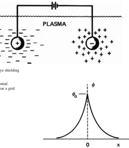
Debye Shielding
Potentials of the order KT/ecan leak into the plasma and cause finite electric fields to exist. Fortunately, this region does not contribute much to the thickness of the cloud (called a sheath) because the potential drops off very quickly there.
The Plasma Parameter
Criteria for Plasmas
For the case of an infinite, transparent grid charged at a potential ϕ, show that the shielding distance is approximately given by. The space between them is uniformly filled by a gas with a density of charge particles. a) Using Poisson's equation, show that the potential distribution between the plates is.
Applications of Plasma Physics
- Gas Discharges (Gaseous Electronics)
- Controlled Thermonuclear Fusion
- Space Physics
- Modern Astrophysics
- MHD Energy Conversion and Ion Propulsion
- Solid State Plasmas
- Gas Lasers
- Particle Accelerators
- Industrial Plasmas
- Atmospheric Plasmas
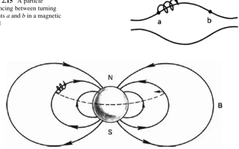
Another important application of plasma physics is the study of Earth's environment in space. The solar wind blows the Earth's magnetic field into a long tail on the night side of the Earth.
Introduction
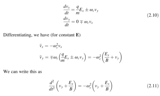
Finite E
In the first half cycle of the ion's orbit in Fig.2.2, it gains energy from the electric field and increases inv⊥and thus inrL. For particles with the same speed but different masses, the lighter one will have a smaller rL and thus drift less per cycle.
Gravitational Field
Approximate the right half of the orbit through a semicircle corresponding to the ion energy after acceleration through the E-field, and the left half through a semicircle corresponding to the energy after deceleration. If Bi is in the +z direction and E is the electrostatic field due to the charge of the beam, calculate the magnitude and direction of the EB drift at r¼a (see Fig.P2.7).
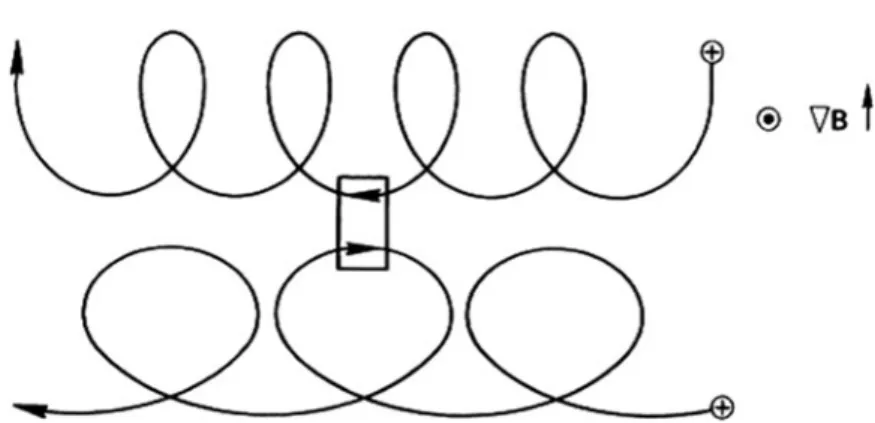
Nonuniform B Field
Curved B: Curvature Drift
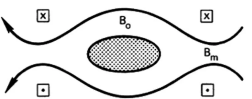
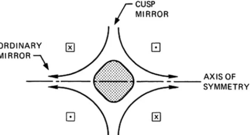
If Bis is high enough in the "throat" of the mirror, v eventually becomes zero; and the particle is "bounced" back to the weak field region. A further example of the mirror effect is the confinement of particles in the Van Allen belts.
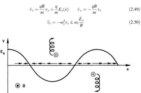
Nonuniform E Field
If the electric field is weak, we can use, as an approximation, the unperturbed orbit to estimate Ex(x). If there is a feedback mechanism that causes the second electric field to enhance the first, it grows infinitely and the plasma is unstable.
Time-Varying E Field
If we now make the assumption that Changes slowly, so thatω2ω2c, then Eq. 2.64) is the approximate solution to Eq. Since vpi is in opposite directions for ions and electrons, there is a polarization current; forZ¼1, that is.
Time-Varying B Field
If an E field is suddenly applied, the first thing the ion does is move in the E direction. Since the plasma is diamagnetic, we have B·dS<0 for ions and >0 for electrons.
Summary of Guiding Center Drifts
Adiabatic Invariants
The First Adiabatic Invariant, μ
In particular, a particle that makes a collision during the compression phase can transfer part of its gyration energy to energy, and this is not taken out again in the expansion phase. Since the B-field vanishes at the center of symmetry, ωci is zero there; andμ is not conserved.
The Second Adiabatic Invariant, J
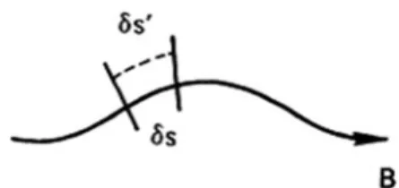
This cannot happen if J is conserved. J determines the length of the line between the breakpoints, and no line has the same length between points with the same jBj. When taking the integral vkδs between the turning points, it may happen that the turning points on δs0 do not coincide with the intersections of the perpendicular planes (Fig. 2.17).
The Third Adiabatic Invariant, Ф
The magnetic field in the center of the room is 1 T, and you can make a large aspect ratio (Ra) approximation where necessary. At t¼0 an electron of small gyroradius is at z¼0 and r¼r0 with v⊥0¼vk0·(⊥and refers to the direction relative to the magnetic field.) (a) Calculate the magnitude and direction of the resulting center of conduction.
Introduction
- Maxwell ’ s Equations
- Classical Treatment of Magnetic Materials
- Classical Treatment of Dielectrics
- The Dielectric Constant of a Plasma
Note that we used E and B in the vacuum equations instead of their counterparts Dan and H, which are related by the constants ε0 and μ0. In the vacuum equation (3.1) we must include both the bound charge and the free charge: .
The Fluid Equation of Motion
- The Convective Derivative
- The Stress Tensor
- Collisions
- Comparison with Ordinary Hydrodynamics
- Equation of Continuity
- Equation of State
- The Complete Set of Fluid Equations
Then all the particles in the fluid element move together and the average velocity u of the particles in the element is equal to the individual velocity of the particles v. The answer is guarded yes and the reasons for this will tell us the limitations of fluid theory.
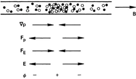
Fluid Drifts Perpendicular to B
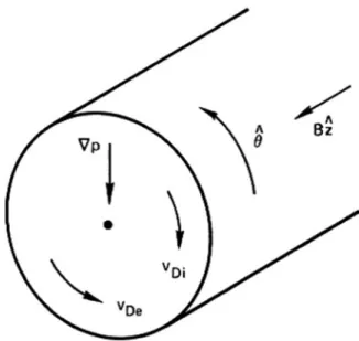
B2 ð3:69Þ In the particle image one would not expect to measure a current if the conduction centers are not drifting. In the presence of a density gradient, the density of conducting centers is not the same as the density of particles.
Fluid Drifts Parallel to B
The latter is the Boltzmann relation, Eq. b) Show that the plasma rotates as a solid body. Since the plasma is quasi-neutral, the gradient exists for both the electron and ion liquids.
The Plasma Approximation
Of course, if only one species can move and the other cannot follow, such as in high-frequency electron waves, then the plasma approximation is not valid and must be found from Maxwell's equations rather than from the ion and electron equations of motion. We will return to the question of the validity of the plasma approximation when we come to the theory of ion waves.
Representation of Waves
Ifω/kis is positive, the wave moves to the right; that is, xincreases in increments to keep kxωtconstant. The phaseδ can be recovered from Ec, since Re Ec ¼Ecosδ and Im Ec ¼Esinδ; so that.
Group Velocity
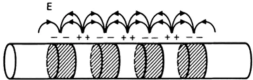
Plasma Oscillations
Either traveling waves or standing waves can be created, as in the case of a stretched rope. Note that the time patterns can be obtained by translating the x-patterns in the right direction, as if the wave were passing a fixed observer.
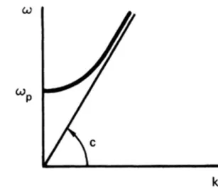
Electron Plasma Waves
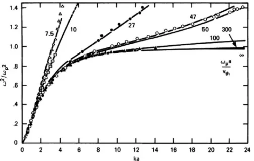
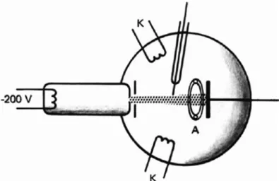
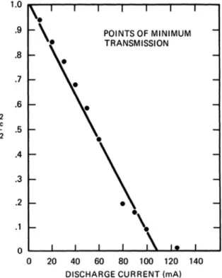
The accumulation of electrons was not realized in the plasma, but in the oscillating coils at the ends of the plasma column. When the oscillator frequency ω varies, the graph of the dispersion curve (ω/ωp)2vs.ka is obtained, while the radius of the column (Fig. 4.10).
Sound Waves
Ion Waves
In ion acoustic waves, the other species (namely electrons) is far from fixed; in fact, electrons are pulled along with the ions and tend to shield electric fields created by the bundling of ions. First, the ion thermal motions spread out the ions; this effect gives rise to the second term in the square root of Eq.
Validity of the Plasma Approximation
This is the same as we obtained earlier (Eq. 4.41)) except for the factor 1þk2 λ2D: Our assumptions have given rise to an error of the order k2λ2D¼ð2πλD=λÞ2: Since λD is very small in most experiments, the plasma approximation is invalid everywhere a thin layer, called a mantle (chap.8), a few λDs in thickness, next to a wall.
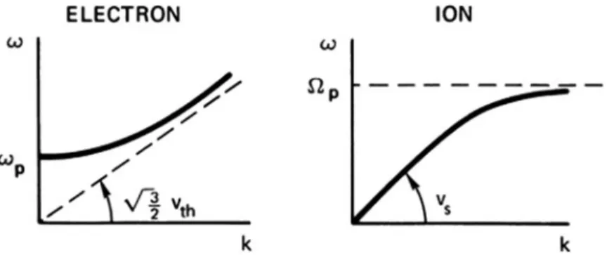
Comparison of Ion and Electron Waves
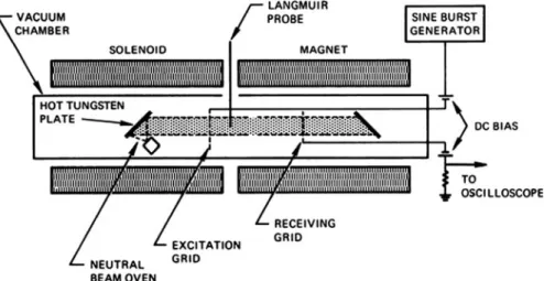
The slopes of such lines give the phase velocities plotted in Figure 4.17 for the two masses and different plasma densities n0. The constancy of υs with ωenn0 is shown experimentally, and the two sets of points for K and Cs plasmas show the correct dependence on M.
Electrostatic Electron Oscillations Perpendicular to B
The existence of the upper hybrid frequency has been experimentally verified by microwave transmission through a magnetic field. One is like the plasma swing and the other is like the top hybrid swing, but both will be modified by the propagation angle.
Electrostatic Ion Waves Perpendicular to B
Electrostatic ion cyclotron waves were first observed by Motley and D'Angelo, again in the aQ-machine (Figure 4.24). In this experiment, the k2v2s term was small compared to the Ω2c term, and the measured frequencies were only slightly above Ωc.
The Lower Hybrid Frequency
If we had used Poisson's equation instead of the plasma approximation, we would have obtained In many low-density plasmas the latter term actually dominates because the plasma approximation is not valid when the Debye length is not negligibly small.
We see that the vacuum relation Eq. 4.76) is modified by a termω2 reminiscent of plasma oscillations. For densities greater than this, Eq. 4.85) cannot be fulfilled for any area and the wave cannot propagate.
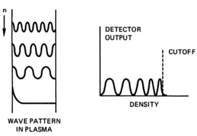
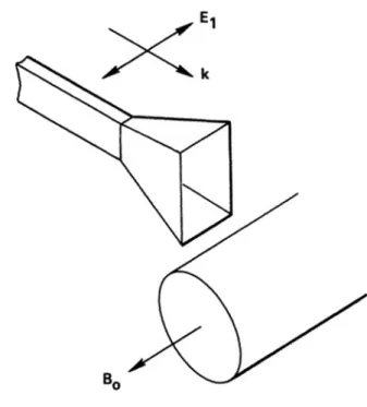
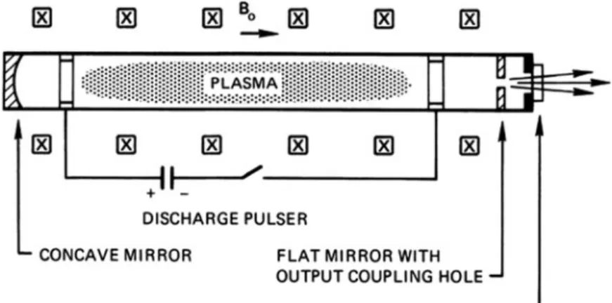
Experimental Applications
Part of the signal goes to the detector through the "reference leg". The other part is sent through the plasma with horn antennas. Perhaps the best known effect of the plasma cutoff is its application to shortwave radio communications.
Electromagnetic Waves Perpendicular to B 0
In plasma physics, it makes more sense to let the "ordinary" wave be the one unaffected by the magnetic field.
¼0 ð4:102Þ Since the coefficientAisω2ω2h;whereωhis is the upper hybrid frequency given by Eq. 4.60), the condition AD¼BC can be written.
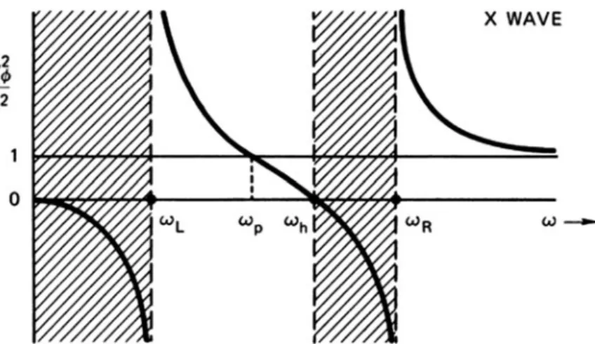
Cutoffs and Resonances
The boundary values of the extraordinary wave are found by setting k equal to zero in Eq. Instead of the usual ω–k diagram, it is more illuminating to give a graph of phase velocity versus frequency; or, more precisely, a graph ofω2/c2k2¼1/n~2vs.ω(Fig. 4.36).
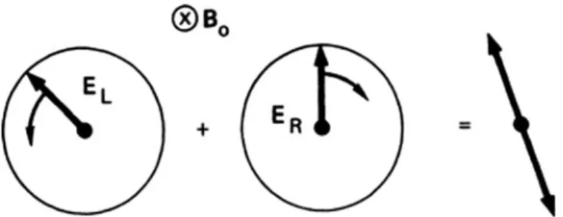
Electromagnetic Waves Parallel to B 0
For the R wave, k becomes infinite at ω¼ωc; the wave is then in resonance with the cyclotron motion of the electrons. The Lwave, on the other hand, has no cyclotron resonance with the electrons because it rotates in the opposite direction.
Experimental Consequences .1 The Whistler Mode.1 The Whistler Mode
Faraday Rotation
Show that there is no Faraday rotation in a positronium plasma (equal number of positrons and electrons). Show that the Faraday angle of rotation, in degrees, of a linearly polarized transverse wave propagating along B0 is given by.
Hydromagnetic Waves
As we saw before, ε is much larger than unity for most laboratory plasmas, and Eq. ð Þ1=2 ð4:125Þ These hydromagnetic waves move along B0 at a constant velocity vA, called the Alfve´n velocity:. vAB. At the point shown, By is in the positive y-direction, so, according to Eq. 4.128), Exists in the positivex direction ifω/kis in this direction.
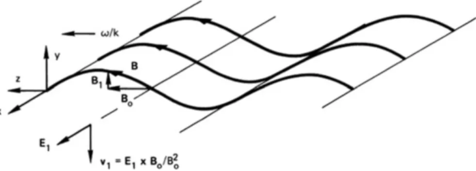
Magnetosonic Waves
It is an acoustic wave in which compressions and rarefactions are produced not by motions along E but by EB motions along E. The phase velocity of the magnetosonic mode is almost always greater than vA; for this reason, it is often simply called "fast".
Summary of Elementary Plasma Waves
Nevertheless, it is a very useful set of equations to consider as a frame of reference for discussing more complex wave motions. Often a complex situation can be understood as a modification or superposition of these basic modes of oscillation.
The CMA Diagram
The upper regions of the CMA diagram correspond to ω ωc: the low-frequency ion waves are found here. The Appleton-Hartree dispersion relation for high-frequency electromagnetic waves propagating at an angle θ to the magnetic field is .
Diffusion and Mobility in Weakly Ionized Gases
Collision Parameters
The probability of loss of momentum can be expressed in terms of the equivalent cross section σ the atoms would have if they were perfect absorbers of momentum. The atoms are thought to be opaque spheres with a cross-sectional areaσ; that is, an electron each time.
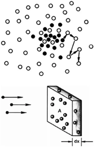
Diffusion Parameters
If a current Γ of electrons is incident on the plate, the current that appears on the other side is Γ0 ¼Γð1nnσdxÞ. Due to the possibility of organized motions (plasma waves), the plasma can spread out in a way that is not truly random.
Decay of a Plasma by Diffusion .1 Ambipolar Diffusion.1Ambipolar Diffusion
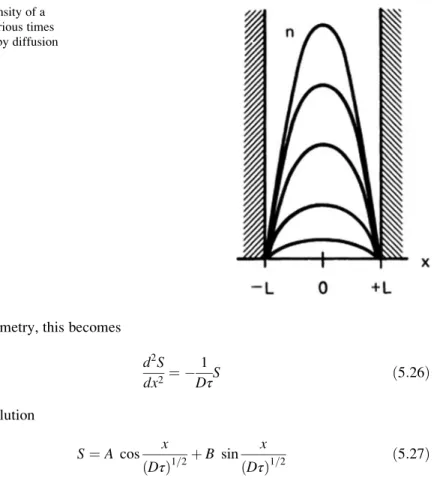
Diffusion in a Slab
This is called the lowest diffusion mode. The density distribution is a cosine, and the peak density decays exponentially with time. Substituting this into the diffusion equation (5.17), we see that each cosine term yields a relation of the form
Diffusion in a Cylinder
Higher diffusion modes with more than one maximum in the cylinder will be given in terms of higher-order Bessel functions, in direct analogy with the plate geometry example.
Steady State Solutions
Constant Ionization Function
Plane Source
Line Source
Recombination
When the density is high, recombination, which is proportional ton2, is dominant, and the density decays reciprocally. After the density reaches a low value, diffusion becomes dominant, and the decay is henceforth exponential.
Diffusion Across a Magnetic Field
Ambipolar Diffusion Across B
However, this electric field can be short-circuited by an imbalance of the fluxes along B. In short plasma columns with the field lines terminating on conducting plates, one would expect the ambipolar electric field to be short-circuited.
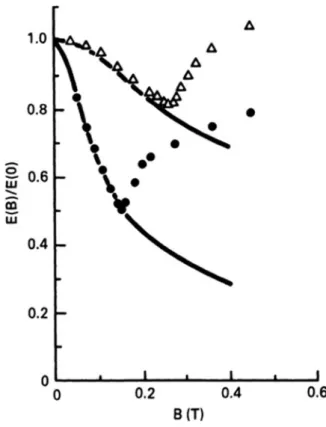
Experimental Checks
Furthermore, the response depends sensitively on the boundary conditions at the ends of the field lines. The theory correctly predicted the value of Bc. The wave, in the form of a helical distortion of the plasma column, was later seen directly in an experiment by Allen, Paulikas, and Pyle at Berkeley.
Collisions in Fully Ionized Plasmas
- Plasma Resistivity
- Mechanics of Coulomb Collisions
- Physical Meaning of η
- Numerical Values of η
- Pulsed Currents
This force is felt when the electron is near the ion; this time is approx. The factor 2.0 comes from the difference in the weighting of the different velocities in the electron distribution.
The Single-Fluid MHD Equations
A less obvious equation is obtained by a different linear combination of the equations of the two fluids. 5.82) with M and subtract the latter from the former. EþvB¼ηj ð5:91Þ The continuity equations for massρ and chargeσ are easily obtained from the sum and difference of the continuity equations of ions and electrons.
Diffusion of Fully Ionized Plasmas
First, D⊥ is not a constant in a fully ionized gas; it is proportional tons. This is because the density of scattering centers is determined not by the neutral atomic density, but by the plasma density itself. Finally, we would like to point out that there is no transverse mobility in a fully ionized gas.
Solutions of the Diffusion Equation
Time Dependence
Time-Independent Solutions
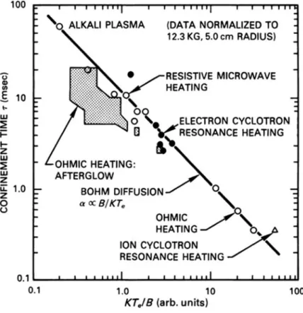
Bohm Diffusion and Neoclassical Diffusion
Suppose that the plasma in a fusion reactor is in the form of a cylinder with a diameter of 1.2 m and a length of 100 m. The increasing magnetic field inside the coil induces a surface current in the highly conductive plasma.
Introduction
Hydromagnetic Equilibrium