FRICTION STIR SPOT WELDING: ENGINEERING ANALYSIS AND DESIGN By
Chase Davison Cox
Dissertation
Submitted to the Faculty of the Graduate School of Vanderbilt University
In partial fulfillment of the requirements for the degree of
DOCTOR OF PHILOSOPHY in
Mechanical Engineering May, 2014 Nashville, TN
Approved:
Dr. Alvin M. Strauss Dr. George E. Cook Dr. David R. DeLapp
Dr. Greg Walker Dr. Jason Valentine
ii DEDICATION
For my wife and daughter
iii
ACKNOWLEDGMENTS
I would like to thank Professor Alvin M. Strauss and Professor George E. Cook for their support and guidance during my graduate career. I would also like to thank Dr.
David R. DeLapp, Professor Greg Walker, and Professor Jason Valentine for serving on my PhD committee and for their numerous contributions to my education and research. I would like to thank John Fellenstein and Bob Patchin in the machine shop for their assistance. I would also like to thank my fellow graduate students, both past and present, in the Vanderbilt Welding Automation Laboratory for their help and support. I would like to thank the Tennessee Space Grant Consortium for their financial support.
Lastly, I’d like to thank my family for their support.
iv
Table of Contents
Page
DEDICATION ... ii
ACKNOWLEDGMENTS ... iii
LIST OF FIGURES ... vii
LIST OF TABLES ... xv
Chapter I. INTRODUCTION ... 1
Background ... 1
Overview of Work ... 3
II. FRICTION STIR SPOT WELDING ... 7
The Friction Stir Spot Welding Process ... 7
Advantages of FSSW ... 8
Friction Stir Spot Welding Terminology ... 9
Process Parameters ... 13
Tool Design ... 16
Material Flow ... 23
Defects and Failure Modes ... 26
Notable FSSW Variations ... 29
III. FSSW MODELING AND SIMULATION ... 31
Introduction ... 31
Analytic (Process) Models ... 32
Heat Generation... 32
Weld Torque ... 42
Axial Force... 46
Thermal Boundary Conditions ... 49
Material Flow ... 52
Computational Modeling Studies ... 60
IV. EFFECT OF PIN LENGTH AND ROTATION RATE ON THE TENSILE STRENGTH OF A FRICTION STIR SPOT-WELDED AL ALLOY: A CONTRIBUTION TO AUTOMATED PRODUCTION ... 69
Abstract ... 69
Introduction ... 70
Experimental ... 72
Results ... 75
Effect of Pin Length and Rotation Rate on Static Weld Strength ... 75
v
Failure Analysis ... 77
Weld Zone Imaging ... 83
Discussion ... 86
Conclusions ... 93
V. THE APPLICATION OF A PINLESS TOOL IN FRICTION STIR SPOT WELDING: AN EXPERIMENTAL AND NUMERICAL STUDY ... 95
Abstract ... 95
Introduction ... 96
Experimental ... 98
Results ... 102
Joint Strength ... 103
Spindle Torque ... 107
Temperature ... 110
Failure Analysis ... 113
Macrosection Analysis ... 114
Numerical Simulation ... 116
Discussion ... 123
Conclusions ... 127
VI. A METHOD FOR DOUBLE-SIDED FRICTION STIR SPOT WELDING ... 128
Abstract ... 128
Introduction ... 129
Numerical Model ... 132
Design ... 132
Thermal Model ... 133
Material Flow Model ... 137
Results ... 140
Experimental ... 141
Rotating Anvil Design ... 141
Using the RAFSSW Process ... 148
Experimental Results ... 150
Macrosection Analysis ... 150
Mechanical Strength ... 151
Process Forces ... 153
Conclusions ... 155
VII. ENERGY INPUT DURING FRICTION STIR SPOT WELDING ... 157
Abstract ... 157
Introduction ... 157
Experimental ... 159
Results ... 161
Axial Force... 163
Spindle Torque ... 164
vi
Spot Weld Energy ... 164
Tensile Shear Strength ... 167
Discussion ... 168
Conclusions ... 172
VIII. ROTATING ANVIL APPLICATIONS FOR FRICTION STIR SPOT WELDING ... 173
Abstract ... 173
Introduction ... 174
Experimental ... 176
Results and Discussion ... 176
Force Control... 176
Non-Matched Rotation Rates ... 183
Triple-Lap Joint Welding ... 189
Al-Steel-Al With Through Hole ... 195
Spot Stich Welding ... 205
Conclusions ... 207
IX. DISCUSSION OF RESULTS ... 209
Overview ... 209
Tool Geometry ... 209
Spot Welding Parameters ... 210
Rotating Anvil ... 211
Numerical Modeling ... 212
X. RECOMMENDATIONS FOR FUTURE WORK ... 213
Friction Stir Spot Welding ... 213
Tool Rotation Feedback ... 213
FSSW Tool Turn Limit ... 213
FSSW of Butt Joints... 214
FSSW with Sealant ... 215
FSSW with “Energy” Control ... 215
XI. CONCLUSIONS ... 217
REFERENCES ... 218
APPENDIX ... 227
A. Design of A Pinless FSSW Tool ... 227
B. Patent Application for Double Sided Friction Stir Spot Welding Method ... 233
vii
LIST OF FIGURES
Figure 1: The friction stir spot welding process. ... 7
Figure 2: Advantages of FSW/FSSW [Mishra] ... 8
Figure 3: An FSSW tool with the shoulder and pin identified ... 9
Figure 4: Cross-section view of an FSSW spot weld [Arul] ... 11
Figure 5: Joint configurations for FSSW ... 12
Figure 6: The FSSW cycle ... 15
Figure 7: FSSW tool profile and pin size (d): (a) straight cylindrical, (b) tapered cylindrical, (c) threaded cylindrical, (d) square, (e) triangular and (f) hexagonal. [Bilici] ... 17
Figure 8: Schematic illustration of FSSW tool geometries (a) cylindrical pin shape (threads not shown in illustration) and (b) triangular pin shape [Badarinarayan 142-48]. 18 Figure 9: Macro images of a) long step spiral pin (CP) and b) off-center hemisphere pin (OC) [Yuan] ... 18
Figure 10: Lap-shear separation load as a function of shoulder penetration depth [Yuan] ... 19
Figure 11: Effect of FSSW pin length (x-axis) and anvil insulation on 6111 aluminum alloy tensile shear strength (y-axis) [Bakavos 2009] ... 20
Figure 12: Schematic of FSSW tool shoulder geometries a) concave, (b) flat, (c) convex [Badarinarayan 814-23] ... 21
Figure 13: Different FSSW shoulder features shown before and after twenty welds: (a) featureless tool, (b) the short flute wiper tool (ii), (c) the long flute wiper tool (iii), (d) the fluted scroll tool (iv), and (e) the proud wiper tool (v) [Bakavos 2011]. ... 22
Figure 14: Schematic illustration of material flow with a pinless tool [Tozaki 2010] ... 24
Figure 15: Material flow observed during FSSW. (a-d) cross section views of the weld formation sequence, (e) plan view below top surface of weld for 0 and 0.5 seconds of dwell time [Bakavos 2011]. ... 25
Figure 16: The hooking defect observed in a FSSW spot weld [Badarinarayan 142-148] ... 27
Figure 17: Relationship between generated heat and process parameters during FSSW [Mijajlovic] ... 33
Figure 18: Experimental apparatus for measuring momentum of friction and axial force [Mijajlovic]. ... 36
Figure 19: Variations of (a) fractional slip and (b) the friction coefficient [Nandan 2006] ... 38
viii
Figure 20: Definition of contact condition, velocity/shear relationship, and contact state variable [Schmidt] ... 40 Figure 21: Spatial variation of heat generation (watts) along the tool/workpiece interface for a) the shoulder b) the pin bottom [Nandan 2007] ... 41 Figure 22: Simplified geometry of the Nunes Rotating Plug model during FSW [Nunes 2011] ... 43 Figure 23: Estimated and experimental torque values for FSW of a) AA2524 and b) Ti- 6Al-4V [Arora] ... 45 Figure 24: Computed axial force using Equation 3.20 (Data from Nunes RP et al.) ... 47 Figure 25: Idealization of weld metal flow around a FSW tool during the plunge stage [Nunes 2012] ... 47 Figure 26: Free body diagram for flow elements around the FSW tool [Nunes 2012] .... 49 Figure 27: Schematic diagram of the pinless FSSW system considered in the model for thermal boundary conditions [Nandan 2006] ... 50 Figure 28: Three incompressible flow fields of FSW. a) rigid body rotation b) uniform translation c) ring vortex [Schneider] ... 53 Figure 29: a) schematic of the velocity field domain. b) flow field from well-tested visco- plastic flow code c) flow field from analytic expression [Arora] ... 54 Figure 30: Flow stress data for Al 6061 and curve fitting values: R2 = 0.996 [Tello] ... 57 Figure 31: Computed contours of viscosity. The contour labels represent logarithm to the base 10 of viscosity in Pa·s [Nandan 2007] ... 58 Figure 32: Variation of viscosity with shear rate according to the Carreau model [Fluent]
... 59 Figure 33: Comparison between experimental and numerical results a) weld cross section b) contour graph of dynamic viscosity [Atharifar] ... 60 Figure 34: Mesh representation for FSSW tool, workpiece, and anvil. b) Boundary Conditions [Awang] ... 61 Figure 35: Deformation and temperature distribution [Awang] ... 62 Figure 36: Temperature vs. radial distance from the center of the tool [Awang] ... 62 Figure 37: Location of thermocouples imbedded in the workpiece (butt joint) [Song] ... 64 Figure 38: Temperature contours during the a) plunge stage, and b) the extraction stage of FSW [Song] ... 65 Figure 39: a) FSSW geometry used for CFD Simulation b) mesh scheme for cylindrical pin c) close up view of mesh scheme [Kim] ... 66 Figure 40: Temperature distribution during FSSW for a cylindrical pin (left) and
triangular pin (right) at t = a) 0.01 sec b) 1.0 sec c) 2.0 sec [Kim] ... 67 Figure 41: Material flow during FSSW for a cylindrical pin (left) and triangular pin (right) at t = a) 1.94 sec b) 1.95 sec c) 1.96 sec ... 68
ix
Figure 42 The Friction Stir Spot Welding Process. A-C: represents the traditional FSSW process using a tool with a pin. The resulting keyhole defect is illustrated. D-F: represents
the FSSW process using a pinless tool. The lack of the keyhole defect is illustrated. ... 71
Figure 43: Clamp orientation relative to the spot welds for each sample. This clamp prevented the top plate from pulling away from the bottom plate during the spot welding process. The holes in the top plate were created off center for alignment purposes with the FSW machine. ... 73
Figure 44: Lap tensile specimen. ... 74
Figure 45: Effect of pin length and rotation rate on static joint strength of spot welds.... 75
Figure 46: FSSW Failure Modes for 750 RPM ... 77
Figure 47: FSSW Failure Modes for 1250 RPM ... 78
Figure 48: FSSW Failure Modes for 1500 RPM ... 79
Figure 49: FSSW Failure Modes for 2000 RPM ... 80
Figure 50: Comparison of failure mode to weld strength. Only 2 welds in the experiment were classified as a mode (i) failure while 12 (60%) of the welds were classified as a mode (ii). The mode (ii) type failures exhibited the highest joint strength when compared to the other failure modes. The remaining welds were classified as mode (iii) failures... 82
Figure 51: Macrosection images of cross-sections of welds. (a) 750 rpm/pinless, (b) 750 rpm/0.010” pin, (c) 750 rpm/0.032” pin, (d) 750 rpm/0.036” pin, (e) 750 rpm 0.038” pin ... 83
Figure 52: Images of bond interface modes and notable failures. (a) A compiled image for the cross section of the pinless tool at 2000 rpm. Bond (i and iii) account for 100% of the interface for this weld. (b) The combination of 750 rpm and a pinless tool resulted in a well formed stir zone with good metallurgical bonding. (c) The 0.032” pin length at 2000 rpm resulted in a weld exhibiting bond (i). (d) The 0.032” pin length at 750 rpm resulted in a good metallurgical bond. A small amount of bond (iii) was observed at the right edge of the interface between the plates. (e) The 0.038” pin length at 2000 rpm resulted in a weld exhibiting bond (i). (f) The 0.038” pin length at 750 rpm resulted in a good metallurgical bond. ... 85
Figure 53: Comparison of theoretical heat generated by the FSSW tools used at the various rotation rates and their resulting average tensile strength. Q’/Q* represents the normalized theoretical heat input calculated for each rotation rate used. Q’ is the individual calculated value for each tool and rotation rate combination and Q* is the maximum calculated value. The average tensile values represented as TS’/TS* were calculated by averaging each of the measured tensile strengths for a given rotation rate for all pin lengths used. TS’ and TS* represent the individual average tensile strength for a given rotation rate and the maximum average tensile strength respectively. ... 88 Figure 54: Comparison of velocity field at various depths (0.02, 0.04, 0.06 and 0.08) created beneath the shoulder during FSSW. Two rotation rates were considered; 750 and 2000 rpm. A pinless and non-zero pin design were considered. V’ represents the
x
magnitude of the 3 dimensional velocity field for a given parameter set (u, v, w, r, z). The velocity is calculated such that r = radius of shoulder or pin. V* represents the maximum calculated value. ... 91 Figure 55: Graphical representation of the observed pin length effect on joint strength.
Region “A” represents the velocity field created by the shoulder. Region “B” represents the velocity field created by two different pin lengths. It can be seen that in the case of the longer pin length, the total velocity field is increased by the pin bottom’s contribution.
Region “C” represents the resultant velocity field. ... 92 Figure 56: The Friction Stir Spot Welding Process. A-C: represents the traditional FSSW process using a tool with a pin. The resulting keyhole defect is illustrated. D-F: represents the FSSW process using a pinless tool. The lack of the keyhole defect is illustrated. ... 97 Figure 57: Spot weld sample geometry ... 99 Figure 58: Instrumented Anvil. Thermocouples are located 1/16th of an inch beneath the surface of the anvil beneath the weld zone. ... 100 Figure 59: FSSW tool with scrolling ... 101 Figure 60: Contour plots of shear load of spot welds vs. all parameters. The label of each access can be seen in the title of each subplot (y-label * x-label) ... 104 Figure 61: Contour plots of spindle torque. The label of each access can be seen in the title of each subplot (y-label * x-label) ... 108 Figure 62: Comparison of experimental, empirical, and analytic torque values ... 110 Figure 63: Contour plots of the peak temperature measured via the thermocouples. The label of each access can be seen in the title of each subplot (y-label * x-label) ... 111 Figure 64: Temperature versus dwell time. The welding tool makes contact at 5 seconds.
... 112 Figure 65: Temperature versus rotation rate. Tool contact at 7 seconds. ... 112 Figure 66: A shear specimen exhibiting the weld pullout mode. a) The top of the bottom plate. The weld nugget remains in the bottom plate. b) The top of the top plate. c) The bottom of the bottom plate. d) The bottom of the top plate. ... 113 Figure 67: Macrosections of spot welds. Hold parameters: 2 sec dwell, 0.006 in plunge depth, 0.5 ipm plunge rate. a) 750 rpm b) 1000 rpm c) 1250 rpm d) 1500 rpm e) 1750 rpm ... 114 Figure 68: Geometry mesh for FSSW simulation... 117 Figure 69: Maximum temperature value at a point located at the bottom-center of the workpiece during welding (1250 RPM, 6 Sec Dwell) for experimental measurement and the values predicted by simulation. ... 118 Figure 70: Development of temperature field within the workpiece during an FSSW spot weld. 1250 rpm, 4 sec dwell. Temperatures are reported in K. The y-axis has units of 10-
4 meters. The x-axis has units of meters. ... 119 Figure 71: Cross section view of velocity magnitude contour from CFD model for a tool rotation speed of 750 RPM ... 121
xi
Figure 72: Cross section view of velocity magnitude contour from CFD model for a tool rotation speed of 1250 RPM ... 121 Figure 73: Cross section view of velocity magnitude contour from CFD model for a tool rotation speed of 1750 RPM ... 122 Figure 74: Regression graphs for a) Shear failure load b) Torque c) Temperature ... 123 Figure 75: Strength of the spot welds vs. the number of rotations made by the weld zone during the weld. ... 124 Figure 76: Dependence of gas consumption on the weight of an automobile [Prangnell]
... 129 Figure 77: The Friction Stir Spot Welding Process. A-C: represents the traditional FSSW process using a tool with a pin. The resulting keyhole defect is illustrated. D-F: represents the FSSW process using a pinless tool. The lack of the keyhole defect is illustrated .... 131 Figure 78: Thermal boundary conditions and mesh used for the workpiece in the FSSW simulation. ... 135 Figure 79: Temperature field within the workpiece during FSSW with a rotating anvil for 1 mm and 2 mm thick workpieces. Temperatures are reported in ºK. ... 136 Figure 80: Cross section view of the velocity contours and arrow surface of the RAFSSW process when joining a) 1 mm and b) 2 mm thick workpieces of Al 6061 T6. A rotation rate of 1000 rpm is used. The contour is taken at the end of the 3 second dwell period, immediately before the tool is retracted. ... 139 Figure 81: The VUWAL FSW Machine. ... 142 Figure 82: CAD drawing of the preliminary RAFSSW device design. ... 144 Figure 83: The RAFSSW Device. The motor can be seen mounted in front of the welding machine. During welding the worktable and rotating anvil would raise causing the belt to slip. ... 146 Figure 84: Plot of accelerometer data from the sample stage during welding with (red line) and without (blue line) the stabilization arm. ... 147 Figure 85: The RAFSSW device. The FSSW tool receives power from the main spindle of the FSW machine. The rotating anvil assembly, stabilization arm and 7.5 HP motor are all mounted to the stage of the FSW machine. The vertical actuation of the RAFSSW device is achieved through a simple combination of the vertical drive of the FSW
machine and the floating stage. ... 148 Figure 86: The welding tool and rotating anvil. A spherically tapered (convex) shoulder with scrolling and a 10.2 mm flat ground into the end. ... 149 Figure 87: Macrosection image of spot welds made using the RAFSSW process. Spot weld created at a) 750 rpm (welding tool and anvil) and a 0.5 second dwell phase and b) 1500 rpm and a 0.5 dwell time. A hooking defect can be seen on the left and right side of the 1500 rpm spot weld macrosection. ... 150
xii
Figure 88: Comparison of joint strengths between spot welds made using the RAFSSW process using 750 and 1500 rpm and two different dwell times in 1 mm thick Al 6061 plate. ... 152 Figure 89: Comparison of joint strengths between spot welds made using the RAFSSW process using 750 and 1500 rpm and two different dwell times in 2 mm thick Al 6061 plate. ... 153 Figure 90: Comparison of welding forces between the traditional FSSW and RAFSSW processes created in the 1 mm (0.04”) thick plate. Axial forces created in 2 mm (0.08”) and 3 mm (0.125”) using the RAFSSW are also presented. ... 154 Figure 91: Pinless FSSW tool with a spherically tapered shoulder. ... 160 Figure 92: Open-loop position control system used for this experiment. The rotation rate, dwell time, plunge depth, plunge and extraction rates are inputs. The plunge depth and dwell time are the limits in this system. The resulting axial force and spindle torque are monitored during welding. ... 161 Figure 93: Axial force during FSSW for different numbers of tool turns. The average axial force is 10.1 kN ± 0.5 kN. For this experiment, an open-loop position control scheme was used. Error bars represent standard deviation. ... 163 Figure 94: Spindle torque (Nm) and energy (J) during spot welding. 1200 RPM, 0.5 sec dwell, 10 tool turns. ... 166 Figure 95: Total spot welding energy generated during FSSW. Error bars represent standard deviation. ... 167 Figure 96: Spot Weld Strength. Error bars represent standard deviation. ... 168 Figure 97: Spot Weld Tensile Shear Strength vs. Spot Welding Energy. Error bars
represent standard deviation. ... 170 Figure 98: Proposed FSSW open-loop control system with energy monitoring. Like with traditional position control, the rotation rate, plunge depth, plunge and extraction rate are still input into the system. Instead of inputting a dwell time, total weld energy is
specified. The plunge depth and total weld energy are now the limits on the system. Once the specified weld energy is generated, the welding tool would retract. ... 171 Figure 99: Axial force during RAFSSW with position control. The desired plunge depth is 0.008 inch. The maximum axial force of RA1 is 6080 N, of RA8 is 6710 N, and of RA18 is 7140 N. ... 178 Figure 100: Vertical position of welding stage during a friction stir spot weld (rotating anvil) without force control. RA1 overshot the desired plunge depth by 0.0018 in (23%), RA8 by 0.0022 in (28%), and RA18 by 0.0018 in (23%) ... 179 Figure 101: Z-Force vs. Plunge Depth. An increase in the plunge depth resulted in a linear increase in the axial force acting on the welding frame. The weld data for this plot is from the experiments performed in Chapter IV. ... 180
xiii
Figure 102: Axial force during RAFSSW with force control. The cut-off force is 4250 N.
The maximum axial force of RAFC5 is 4645 N, of RAFC8 is 4581 N, and of RAFC9 is 4843 N. RAFC5 exceeded the cut-off force by 9%, RAFC8 by 8%, and RAFC9 14%. 181 Figure 103: Vertical position of welding stage during a friction stir spot weld (rotating anvil) with force control... 182 Figure 104: Tensile shear strength of spot welds made using non-matched rotation rates between the FSSW tool and rotating anvil. The rotation rate of the FSSW tool for all cases was 1200 rpm. The rotating anvil had rotation rates of 1200 (0 rpm difference), 1500 (300 rpm difference), and 1800 (600 rpm difference). ... 184 Figure 105: Total spot weld energy of spot welds made using non-matched rotation rates between the FSSW tool and rotating anvil. The rotation rate of the FSSW tool for all cases was 1200 rpm. The rotating anvil had rotation rates of 1200 (0 rpm difference), 1500 (300 rpm difference), and 1800 (600 rpm difference). ... 185 Figure 106: Tensile shear strength (kgf) vs. total spot weld energy (kN). Increase in weld energy results in a decrease in joint strength. ... 186 Figure 107: Numerical simulation results of the double-sided FSSW process showing the temperature contours within the workpiece during welding using non-matched rotation rates. ... 187 Figure 108: Acura’s “3D Lock Seam” technology created to join Al-Steel-Al in a triple- lap joint configuration. ... 190 Figure 109: Triple-lap joint configuration used for the Al-Al-Al and Al-Steel-Al spot welds. ... 191 Figure 110: Macrosection of an Al-Al-Al triple lap spot weld made using RAFSSW. . 192 Figure 111: Interlocking of the top and bottom plate with the thicker middle plate of an Al-Al-Al triple-lap joint made using the RAFSSSW process. ... 192 Figure 112: Al-Steel-Al triple lap spot weld with RAFSSW ... 193 Figure 113: No mixing or mechanical interlocking was observed for the Al-Steel-Al RAFSSW joint. ... 194 Figure 114: Cross section of an aluminum to steel FSSW spot weld using a tool that penetrates into the steel sheet [Bozzi] ... 196 Figure 115: Aluminum plastically deformed into the threaded hole. a) top view of
extruded weld zone material b) side view of threads c) side view with a standard nut attached to the threads. ... 197 Figure 116: The proposed through hole method. A 0.125 inch hole is punched in the steel directly in line with the RAFSSW weld zone. The size, location, and orientation may be altered. ... 198 Figure 117: % Volume of the available material to be extruded into the through hole according to the selected diameter of the through hole. ... 199 Figure 118: Tensile shear strength of spot welds made using the through hole with the RAFSSW process. Three cases are presented; no hole, center hole, and an offset hole.
xiv
The dwell time and control force for each case are listed above (or within) their
respective case. For all cases the welding tool and anvil had a rotation rate of 1200 rpm.
... 201 Figure 119: Al-Steel-Al with a through hole. 1200 rpm, 1 sec, 4250 N control force. The extruded material has not completely filled the volume of the through hole. No weld joint is formed. ... 201 Figure 120: Al-Steel-Al with a through hole. 1200 rpm, 1 sec, 8000 N control force. The extruded material from the top and bottom sheet has not completely filled the volume of the through hole. A weld joint was formed within the through hole however. ... 203 Figure 121: Al-Steel-Al with through hole. 1200 rpm, 5 sec, 8000 N control force. The extruded material from the top and bottom sheets has completely filled the volume of the through hole. There is no observable joint line... 204 Figure 122: The Friction Stir Spot Stitch welding process. d is the spacing between each FSSW spot weld. ... 206 Figure 123: A series of overlapping spot welds created using the RAFSSW process. .. 207 Figure 124: Estimated torque vs. experimental torque for various plunge depths. ... 232
xv
LIST OF TABLES
Table 1: FSSW tool dimensions and material... 72
Table 2: Chemical composition (% weight) of Al 6061-T6 ... 99
Table 3: Mechanical properties of Al 6061-T6 ... 99
Table 4: Experimental factors and levels ... 102
Table 5: Experimental design for FSSW using a pinless tool ... 103
Table 6: Regression coefficients for shear load, spindle torque and temperature ... 106
Table 7: Temperature dependent material properties ... 120
Table 8: Temperature dependent material properties of Al 6061 T6... 138
Table 9: Experimental Welding Parameters ... 159
Table 10: Experimental spot welding results. ... 162
Table 11: Experimental results for the non-matched rotation rates for the FSSW tool and rotating anvil. ... 183
1 CHAPTER I
INTRODUCTION
Background
Friction stir welding (FSW) was invented by Wayne Thomas at The Welding Institute (UK) in 1991. As a solid-state joining process capable of joining light-weight metals with lower melting points, FSW quickly received the attention of many
researchers around the world. In 1996, NASA began to investigate the use of Al-Li 2195 in the manufacture of the external fuel tanks in an effort to reduce the cost of shuttle launches. The difficulties in joining this alloy with traditional fusion techniques drove NASA engineers to explore FSW as a possible alternative. In 2005, just nine years later, NASA successfully took the FSW process from the laboratory to the manufacturing floor when external tank 134 took flight [Romine]. NASA’s success with the process
demonstrates the need and willingness of manufacturers to adopt new technologies in an effort to reduce cost and improve efficiency.
While FSW has been the focus of a great deal of research for more than two decades, friction stir spot welding (FSSW) didn’t become a serious topic of interest until the early 2000’s. The initial development of FSSW was performed by Sumitomo Light Metal Industries, LTD., Mazda, Kawasaki Heavy Industries, LTD., and Norsk Hydro. In 2003, Mazda implemented FSSW in the assembly of the rear door panel of their RX-8, the first noted application of the process [Mishra]. This quick three year turnaround compared to the NASA example above speaks to the level of understanding of the
2
FSW/FSSW processes garnered by the welding community in the first decade of its existence.
In FSSW, the joint is created by plunging a rotating tool into a weldment until the tool’s shoulder reaches a desired penetration depth. It will remain at this depth for a specified length of time, at which point the tool is retracted. Unlike fusion welding, FSSW does not melt the parent material, require consumables such as filler rod, shielding gas, or welding sticks, and uses 99% less energy to create the weld [Feldman]. For these reasons FSSW can be considered a “green technology”. The FSSW process can be characterized by three main parameters: rotation rate, plunge depth, and dwell time.
Compared to the multitude of parameters involved in resistance spot welding, FSSW presents the operator with a simpler, more controllable process. Using technologies like self-piercing rivets affords manufacturers some of the same advantages of FSSW but adds to the overall complexity and weight of the design and increases the overhead for production.
One identified drawback of this process is that the tooling leaves a keyhole (the size of its dynamic volume – the volume created by rotating the tool’s geometry) in the weld during retraction that requires removal via either post-processing or costly, highly specialized tool design. As such, pinless tool designs have been identified in the literature as a low-cost alternative in this situation. However, there exists very little information on the topic of the application of a pinless tool for FSSW and it is the purpose of this work to expand upon the understanding of the process through numerical simulation and experimentation.
3
Overview of Work
Chapters II and III presents a review of previously published research on the topic of friction stir spot welding. Chapter II considers experimental investigations (methods and results) while Chapter III focuses on analytic and numerical models and their results.
These chapters form the basis for the motivation of this dissertation.
Chapter IV covers the initial efforts on FSSW with a pinless tool. This work helped in understanding the role the pin and shoulder play in FSSW. It is accepted that for joining a specific thickness of plate there exists an optimal pin length and that the use of a longer pin will result in a lesser quality weld. It has also been shown that a pinless tool can be used to create spot welds that are approximately 90% as strong as those created with a pin of optimal length. However, the addition of a pin of any length greater than zero and less than the optimal length will result in a proportional increase in weld strength [Bakavos]. This claim is supported by interpolating the resulting weld strengths created with a pinless tool and a tool with a pin of nearly optimal length. In this work, sub-optimal pin lengths (pin lengths that do not penetrate the bottom sheet) were tested and it was found that the inclusion of such a pin is detrimental to weld quality. The results of an analytic model of the material flow during spot welding found that, for thin sheet, the shoulder largely contributes to the shape and size stir zone of the spot weld. It was found that unless the pin is long enough to contribute to the effective size of the stir zone it will only leave a keyhole in the spot weld, reducing the load carrying capacity.
Chapter V continues the investigation of the use of pinless tools for FSSW. A new spot welding tool was developed with a spherically tapered and scrolled shoulder.
4
Experiments determined that, in addition to providing additional stirring in some instances, the inclusion of a pin added to the overall stability of the process. Using the traditional pinless tool required the need for rigid clamping due to the tool “chattering”
during the initial plunge phase of spot welding. The spherically tapered shouldered improved the stability and the tolerance of the FSSW process. This new tool was then used in a large experimental study to investigate the effect the rotation, plunge, and extraction rates and the dwell time had on weld quality. The plunge rate had been previously identified in the literature as the most important parameter for FSSW. The results found the plunge rate to be almost negligible when compared to rotation rate, dwell time, and plunge depth. By comparing the experiments with the data presented in the literature one is led to conclude that welding with parameters that result in lower heat inputs resulted in higher quality welds i.e. low rotation rates and short dwell times. The data that supported the claim on the importance of plunge rate was actually found to be largely dependent on pin length and as a result, plunge rate. The use of a pin requires a slower plunge rate which can significantly increase the heat input into the weld during the plunge stage. By eliminating the pin it is possible to drastically reduce the cycle time of the process by eliminating the need for a lengthy plunge phase.
A transient CFD model was created for the pinless FSSW tool to understand the material flow and heat transfer during welding. The model was found to be in good agreement with experimental temperature measurements made during welding. It was found that the majority of the material within the weld zone rotates at a much lower rate (< 5%) than the FSSW tool. Combining the results of the CFD model with the
experimental data it was determined that the highest weld quality was achieved when the
5
weld zone completed approximately one complete rotation during welding. “Over- stirring” the spot weld was found to negatively affect weld quality.
Chapter VI introduces the idea of using a rotating anvil for FSSW and presents an in-depth look into the process. The objective was to improve the weld quality by
increasing the size of the stir zone and to increase the thickness of plate that could be joined with a pinless tool. A transient CFD model was created to help understand how the addition of a rotating anvil would affect the material flow in the stir zone and to aide in tool design and parameter selection. A device was designed and built so that a rotating anvil could be tested using the existing FSW machine at Vanderbilt. After several iterations the process was successfully able to create quality spot welds reliably. In addition to being able to weld material up to 0.125 inches thick (both workpieces are 0.125 inches thick for a total joint thickness of 0.25 inches), the initial objective of the device, it was also found to improve the strength of the welds made in thinner plate. The rotating anvil also helped to reduce the axial load experienced during welding and lowered the cycle times of the process. The rotating anvil is a promising technology that is already beginning to garner the interest of the FSW community for its applications in automotive and aerospace manufacturing.
Chapter VII investigates the effect tool rotations have on the quality of the spot weld. To achieve this goal, different combinations of rotation rate and dwell time were investigated. A linear relationship was found to exist between the number of tool rotations completed during the spot weld and the resulting tensile shear strength. Spot welds that only completed 10 rotations were 177% stronger than those created at 50 tool rotations. Further investigation revealed that the energy generated during the welding
6
operation had strong linear relationship to the tensile shear strength. A modified open- loop position control system is proposed that could monitor and limit the energy generated during friction stir spot welding by adjusting the dwell time.
Chapter VIII explores several novel applications of the rotating anvil for FSSW including triple-lap joints and a “stitch” welding method. First, the operation of the welding process is improved by implementing an open-loop force control system.
Selecting axial force as the input variable resulted in a more repeatable process and improved the cycle time. Additionally, Non-matched rotation rates between the welding tool and anvil are also investigated.
7 CHAPTER II
FRICTION STIR SPOT WELDING
The Friction Stir Spot Welding Process
Figure 1: The friction stir spot welding process.
FSSW, as stated in the introduction, is a solid-state joining process, meaning the base metal is not melted during welding. Like in FSW, the process begins by plunging a rotating tool into the workpiece. During the plunge, the tool begins to heat the workpiece via frictional contact. As the temperature of the workpiece increases, the material in the immediate vicinity of the FSSW tool begins to soften, allowing for plastic flow of the weldment material. Once the tool reaches the desired level of penetration into the workpiece the plunge motion of the tool is halted and the tool continues to rotate for a specified length of time. During this “dwell period”, the material continues to experience plastic deformation. The shoulder of the FSSW tool provides a forging force and retains the plastically deformed material from being expelled from the weld zone. The forging
8
force places a large axial load (perpendicular to the workpiece) on the welding frame and it is supported by the use of a rigid backing anvil. After the dwell period is complete, the rotating tool is retracted from the workpiece. The weld is formed, almost immediately, when the tool disengages from the workpiece (Figure 1).
Advantages of FSSW
The advantages of FSSW when compared to other welding technologies are the same as those identified by Mishra et al. for FSW and can be seen in Figure 2. Because of the advantages FSW/FSSW provides manufacturers, the process is beginning to see more applications ranging from the 2013 Honda Accord [Honda] to the newest Apple iMac desktop computers [Dillet]. Despite these advantages, FSSW is still a long ways from being used by the mechanic in your local auto-garage due to the large process forces during welding. These large forces incurred during the process necessitate the use of large rigid robots to perform the welds [Cook].
Figure 2: Advantages of FSW/FSSW [Mishra]
9
Friction Stir Spot Welding Terminology
Process Terminology
It is important to establish a common language when discussing FSSW and as such, key terms will be defined in this section. When appropriate the terminology outlined by Threadgill et al. will be used to discuss FSSW [Threadgill].
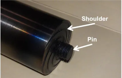
The FSSW tool is considered to be the “whole of the rotating device between the machine spindle and the workpiece.” The shoulder of the tool can be defined as the component of the tool that rests on top of, or slightly beneath, the workpiece and is designed to generate heat via frictional contact. The pin or “probe” of the tool can be defined as being invariably smaller in diameter than the shoulder and completely plunged into the workpiece during welding (Figure 2).
Figure 3: An FSSW tool with the shoulder and pin identified
10
The term “tool rotation speed” is the preferred term to describe tool rotation. The direction of rotation is defined from a top-down view; the use of the terms clockwise or counter-clockwise is appropriate.
The distance the tool’s shoulder penetrates into the workpiece during welding is defined as the “heel plunge depth” or “plunge depth”. This term is sometimes incorrectly used by members of the FSSW welding community to describe the amount the pin penetrates into the workpiece or, even worse, used to describe the length of the pin. Any alternate uses of this term should be avoided as it is misleading for the reader.
The time the tool remains plunged into the material is defined as the “dwell time”.
The velocity at which the tool plunges into the material is defined as the “plunge rate”
and the velocity at which the tool is withdrawn from the weld be defined as the
“extraction rate”.
The process forces of concern during FSSW are the axial force, defined as the force experienced by the tool during welding perpendicular to the workpiece, and the spindle torque, defined as the torque acting about the tool’s vertical axis (of rotation) during welding.
The keyhole is a result of the FSSW process and occurs when the tool is retracted from the weld. The shape and size of the keyhole are dependent upon the geometry (dynamic or swept volume) of the tool used to make the spot weld and the plunge depth selected.
11 Weld Zone Terminology
Figure 4: Cross-section view of an FSSW spot weld [Arul]
The cross section view of a spot weld made using FSSW (Figure 3) has a
significantly different appearance than that of a conventional FSW weld, the most notable being the presence of the keyhole. The area around the pin and shoulder represent the stir zone while the slightly darker area represents the thermomechanically affected zone (TMAZ). The stir zone is defined as being the material in immediate contact with the tool during welding. The TMAZ is defined as being affected by both heat and deformation.
Two unwelded regions of the interface, labeled with x’s in Figure 3, can be seen at the edge of the weld zone. The heat affected zone (HAZ) is defined as being affected only by heat [Threadgill]
Joint Configurations
FSSW is typically restricted to primarily one or two joint configurations. The most common being the lap joint. In the lap joint configuration, one sheet or plate is placed directly on top of another sheet. The weld is then made by plunging the tool into
12
the workpiece such that the shoulder rests on the top sheet while the pin penetrates into the bottom sheet. This joint type is illustrated in Figure 4.
The other less common joint type for FSSW is the butt joint (Figure 4.b). In the butt joint configuration two sheets of identical thickness are abutted against each other.
For this case, the spot welding tool is plunged into the seam between the two plates.
For either case the joint-line is semi-infinite. Simply put, it is an unavoidable consequence that there will be a “crack” that will terminate somewhere along the
interface between the base material and weld zone. This “crack” will occur whenever the joint line is not completely eliminated during the welding process and is not limited to FSSW e.g. the use of FSW for a lap joint configuration would also encounter this issue.
Figure 5: Joint configurations for FSSW
13
Process Parameters
As stated in the previous sections, the FSSW process is dependent on a handful of process parameters that include tool rotation speed, plunge rate, dwell time, and plunge depth. Other parameters may be of interest, especially for some of the variants of FSSW that will be discussed in later sections, and should be noted when relevant. In this section the process parameters investigated in the literature will be discussed.
The tool rotation rate is a dominant process parameter in FSSW as it is
responsible for the heat input into the weld. A wide range of rotation rates can be used for FSSW depending on the application and is more often restricted by the capabilities of the spot welding machine being used. A study by Karthikeyan et. al. [Karthikeyan] evaluated tool rotation rates between 600 and 1800 rpm while Arul et. al.[Arul] evaluated rotation rates between 1500 and 3000 rpm. These two studies effectively capture the majority of the tool rotation rates presented in the literature concerning the joining of aluminum alloys. The tool rotation rate is proportional to the heat input into the weld. The optimal condition for tool rotation rate will depend on the selection of the other process
parameters, tool geometry, and the material(s) being welded.
The plunge rate largely goes unreported in the FSSW literature despite being identified by Karthikeyan et al. as being the parameter with the greatest influence on the tensile shear fracture load [Karthikeyan] of the resultant spot weld. The time to complete the plunge will depend on the geometry of the FSSW tool, primarily the pin length, the plunge depth, and plunge rate. Higher plunge rates will place higher axial loads on the welding machine. Plunge rates reported in the literature range from 0.4 [Tozaki 2007] – 6.0 [Bakavos] inches per minute. Depending on the combination of FSSW tool and
14
plunge rate the plunge stage process can require anywhere from less than a second to more than a minute.
The dwell time of the process is the window during which the weld is created by maintaining the tool at the desired weld height and may or may not be longer than the plunge and extraction times. The depiction of the process in Figure 6 shows the dwell time as being longer than the plunge and extraction times. As previously stated, during this part of the process, the material beneath the FSSW tool is experiencing severe plastic deformation which will lead to the formation of the weld. The short dwell times
associated with FSSW, 0 – 10 seconds, result in a transient, or dynamic, process, much different than that of the relatively steady-state FSW process. This short timespan may increase the difficulty of implementing a closed-loop feedback control like those used for FSW.
15
Figure 6: The FSSW cycle
The plunge depth can be thought of as the contact condition or rather the amount of contact that exists between the FSSW tool’s shoulder and weldment during welding. If the plunge depth is too large, more material will be displaced than the shoulder is
designed to contain and excess weld flash will form. If the plunge depth is too shallow there will not be a sufficient forging force and the weld may not be properly formed. For a traditional flat-shouldered tool this acceptable window of plunge depths ranges has been experimentally observed to be only ± 0.003 of an inch. A poor selection of plunge depth is tied to the observation of several different types of flaws and defects and will be discussed in a later section. In FSW, the plunge depth (contact condition) is often time maintained via force control, which as previously mentioned, may not be a viable option for FSSW. This issue may be addressed by creating more robust FSSW tool designs.
16 Tool Design
The design of the FSSW tool is paramount for weld quality and as such, is a popular topic for researchers working with FSSW. In addition to weld quality, the selection of the tool design has a profound effect on tool performance, load bearing ability, tool lifetime, and process economics. The focus of this work will be in joining materials with relatively low melting points, such as aluminum, which are commonly welded using steel tools [Rai]. The observed wear experienced by tools made from steel during the FSSW of traditional aluminum alloys is negligible and will not be discussed at length in this work.
The geometry of the tool affects the heat generated during welding, plunge force, spindle torque, and the material flow during welding. Dimensions of the shoulder and probe, the inclusion of features on the probe and/or shoulder, and the shape of the shoulder and probe for FSSW will be discussed in this section.
Probe Geometry
A wide variety of probe shapes have been investigated for FSSW. Bilici et al.
reviewed six different probe shapes to identify the optimal geometry for joining polyethylene sheets using FSSW (Figure 7). The geometry of the probe was found to significantly affect the thickness of the weld nugget and tensile strength. Of those, the tapered cylinder (TC) was found to create the strongest welds at similar plunge depths [Bilici].
17
Figure 7: FSSW tool profile and pin size (d): (a) straight cylindrical, (b) tapered
cylindrical, (c) threaded cylindrical, (d) square, (e) triangular and (f) hexagonal. [Bilici]
A modified triangular probe design was introduced by Badarinarayan et al. and was compared to a more traditional threaded probe tool for joining Al 5083 (Figure 8).
The tool geometry was found to affect the formation of a “hook” at the joint interface, a common defect found to occur when welding in the lap-joint configuration. The severity and shape of the hook was reduced when using the triangular shaped pin and resulted in welds that were twice as strong as those created with the threaded cylindrical probe.
Successive rotation of the asymmetric geometry of the triangular probe was found to improve material flow around the probe in the radial direction while the threads were found to improve material flow in the vertical direction [Badarinarayan 142-48]. A more detailed look at material flow during FSSW will be presented in the following sections.
18
Figure 8: Schematic illustration of FSSW tool geometries (a) cylindrical pin shape (threads not shown in illustration) and (b) triangular pin shape [Badarinarayan 142-48].
The tool probe designs presented thus far are fairly standard and their forms can be found in-use for FSW as well. Yuan et al. presented two unique tool probe designs for spot welding Al 6016-T4 using FSSW; the first being a long step spiral pin (CP) and the second being an off-center feature tool with three hemispherical pin features (OC) (Figure 9) [Yuan].
Figure 9: Macro images of a) long step spiral pin (CP) and b) off-center hemisphere pin (OC) [Yuan]
19
Their results indicated that both tool pin designs resulted in spot welds of about the same maximum mechanical strength, ≈ 3.3 kN, at the same process parameters (Figure 10).
This work by Yuan et al. is one of only a few that compares a traditional pin tool to one without a pin (sudo-pinless in this instance). More discussion will follow on the
differences between a pin and pinless tool design.
Figure 10: Lap-shear separation load as a function of shoulder penetration depth [Yuan]
Probe Length
The length of the FSSW probe, or pin, is typically selected on the basis of workpiece thickness, i.e. thicker workpiece requires a longer probe. Tozaki et al. found that the tensile shear strength of the weld increased with increasing probe length (above 25% bottom sheet penetration) regardless of tool rotational speed or dwell time. The
20
increase in shear strength associated with the longer probe lengths was attributed to an increase in the size of the weld nugget [Tozaki 2007]. Bakavos et al. found that the probe lengths that penetrated the bottom sheet by more than 20% negatively affected the tensile shear strength of the weld. In the same study, a pinless tool was found to create welds of comparable strength to those created with a traditional tool with a probe (Figure 11).
Figure 11: Effect of FSSW pin length (x-axis) and anvil insulation on 6111 aluminum alloy tensile shear strength (y-axis) [Bakavos 2009]
Shoulder Geometry
The shoulder geometry of the FSSW tool largely contributes the heat generated during welding, provides the forging force needed to create the weld, and retains the plasticized material within the weld zone. By manipulating the shape and form of the shoulder researchers have been able to improve upon these important functions. The
21
inclusion of features on the shoulder has been shown to increase the shoulder’s effect on the plasticized material’s flow field. The diameter of the shoulder is proportional to heat generated during the weld, spindle torque, axial load, and the volume of the weld zone.
The details of these relationships will be discussed in later sections.
The shape of the FSSW tool’s shoulder is typically concave, flat, or convex (Figure 12). Badarinarayan et al. investigated the differences these different geometries may have on the mechanical properties of spot welds made at identical parameters. The authors claim a 15% improvement in mechanical strength using the concave shoulder when compared to the convex shoulder [Badarinarayan 814-23]. However, in the discussion of their experimental approach they are not clear as to why they chose the selected plunge depth. As previously stated, the selection of a plunge depth for an FSSW tool is very sensitive to position and as such, a large difference in mechanical properties would be expected if an arbitrary plunge depth was selected for three different shoulder geometries. For example, the optimal plunge depth for a concave shoulder may not be the same as that of a flat or convex shoulder.
Figure 12: Schematic of FSSW tool shoulder geometries a) concave, (b) flat, (c) convex [Badarinarayan 814-23]
22
The shoulder of the FSSW tool may include features to better contain material and improve upon its contribution to stirring during welding. The inclusion of shoulder surface features has been confirmed to greatly affect surface roughness and metal deformation in the uppermost layers of the weld zone. Additionally, by incorporating these shoulder features in the design researchers have been able to improve the fatigue resistant properties of the weld zone [Burford].
Figure 13: Different FSSW shoulder features shown before and after twenty welds: (a) featureless tool, (b) the short flute wiper tool (ii), (c) the long flute wiper tool (iii), (d) the fluted scroll tool (iv), and (e) the proud wiper tool (v) [Bakavos 2011].
Bakavos et al. studied different shoulder geometries for FSSW using a pinless tool design (Figure 13). The features investigated were variations of a “wiper” and
“scroll” design. The variations of the wiper tools had six symmetrically arranged
machined flutes cut into the surface of the shoulder that ended before the outer diameter.
The scroll tool design consisted of a machined fluted scroll that started at the center of the shoulder and ended at the outer diameter. As previously mentioned, a pinless FSSW tool design is an attractive alternative to the traditional probe tool design because of the
23
elimination of the key-hole. When using shoulder features on a pinless tool, it was found that a balance must be kept between the tool coupling with top sheet before the
temperature of the material becomes high enough to achieve bonding in the radial and vertical directions [Bakavos 2011]. If the tool couples too strongly with the top plate it may be difficult to create a quality weld due to cracking in the parent material. The use of the scroll and wiper features on a pinless shoulder design was found to strongly influence the flow of material during welding.
Material Flow
The flow of plasticized metal during spot welding with a pinless tool is dependent upon the selection of process parameters and the design of the FSSW tool’s shoulder which has been discussed at length. During welding, the material from the top sheet is pushed down into the bottom sheet where material is displaced outward in the radial direction and, given enough process time, back up into the top sheet where it will be re- incorporated into the stir zone (Figure 14). The displacement of the material from the bottom sheet into the top sheet may result in a hooking defect which will become more pronounced with longer dwell periods.
24
Figure 14: Schematic illustration of material flow with a pinless tool [Tozaki 2010]
Using aluminum alloys with different copper content and metallographic techniques, Bakavos et al. [Bakavos 2011] were able to experimentally visualize the material flow of a spot weld made using a pinless tool with features (Figure 15). The weld samples were prepared by using a three-plate approach in which the bottom sheet was split along the weld center. The result nicely captures the evolution of the material flow from the top sheet into the bottom sheet. For a dwell time of just 0 seconds, it can be seen that stir zone is limited to the top sheet however the joint line in the bottom plate has experienced slight displacement. After 2.5 seconds the stir zone can be observed to completely penetrate into the bottom plate and the joint line in the bottom plate is completely incorporated into the weld zone. The development of the hooking defect during welding is also shown (highlighted by the dashed line).
25
Figure 15: Material flow observed during FSSW. (a-d) cross section views of the weld formation sequence, (e) plan view below top surface of weld for 0 and 0.5 seconds of dwell time [Bakavos 2011].
26
Defects and Failure Modes
Spot welds made using FSSW are not immune to defects. In common with other friction welding processes, the FSSW metallurgical bond is created through the
application of high pressure, heat, and a means for deformation. However, due to a lack of tool translation and a probe, it is sometimes difficult to create a strong bond due to a lack of material flow when using a pinless FSSW tool design. The most common defects encountered with FSW are voids, joint line remnants, hooking defects, top-sheet thinning, and root flaws. Voids, or volumetric defects, are not typically observed in FSSW due to the symmetric nature of the process. A root flaw, or incomplete root penetration, is a defect associated with the butt-joint and is not an issue for FSSW of lap-joints.
The most detrimental weld defect, a defect unique to FSSW with a pinless tool, is a total lack of weld consolidation stemming from a combination of insufficient forging force, rotation rate, and/or dwell time. Insufficient forging force can be caused by a poor selection of the plunge depth parameter, run-to-run variations in workpiece dimensions, or robotic linkage deflection. Other contributing factors could be tool geometry,
excessive weld surface contamination, or material thickness (material selection is too thick i.e. beyond the capability of the process). In the case of this defect, the stir zone never fully propagates into the bottom sheet and the joint is never formed.
The hooking defect, named for its distinct shape, is a characteristic flaw found in both FSW and FSSW of lap-joints. A partial metallurgical bond, the hook is formed in the weld zone at the interface of the workpieces. The severity of the “hook” depends largely upon the geometry of the tool and the process parameters selected. The hook forms when the weld zone penetrates into the bottom sheet which in turn creates an
27
upward bending of the joint interface. The oxides that are present on the surface of the workpiece may or may not be completely incorporated into the weld zone which results in the variation of the bonding condition. The presence of the hook may diminish the mechanical properties of the spot weld since failure can occur along the hook when placed under a load [Badarinarayan 142-48]. In Figure 16 the distinction between an unbonded, partially bonded, and completely bonded region can be seen.
Figure 16: The hooking defect observed in a FSSW spot weld [Badarinarayan 142-148]
The thin oxide layer that exists along the joint interface before welding may also remain within the weld zone after the joint has been formed. Though it is referred to as a defect or imperfection, this is not an accurate classification as it is virtually unavoidable.
The oxide particles are observed to form a wavy path that delineates from the original
28
joint line. The joint line remnant does not typically negatively affect the mechanical properties of the spot weld [Threadgill].
Top-sheet thinning, or effective thickness, is a term used to describe the minimum thickness of the spot weld measured beneath the shoulder (not within the key-hole) and is a result of the selected plunge depth. This effect is caused by the shoulder mechanically displacing material during the plunge and dwell phases of the process. While more stirring can be achieved by increasing the plunge depth the load-bearing capability may begin to suffer as the cross-section of the weld decreases.
During the spot welding process excess material displaced by the FSSW tool is expelled from under the shoulder and out of the weld zone (Figure 4). This can result in thin flakes of material that can easily be brushed off of the weld surface to a thick ring of material that surrounds the spot weld. In addition to being a cosmetic nuisance, the formation of weld flash removes material that would otherwise be in the weld zone and can lead to a weaker weld joint. Weld flash can be reduced or eliminated by proper tool geometry and parameter selection.
When a FSSW spot weld is subjected to excessive loading three distinct failure modes are typically observed, the first being the “shear mode”. This mode is
characterized by a complete separation of the top and bottom plate with the weld nugget remaining in the top sheet. The fracture occurs along the original joint line interface between the top and bottom plates. The “nugget pullout” failure mode is again characterized by a complete separation of the top and bottom plate. However for this mode the nugget remains attached to the bottom sheet. For this mode the fracture occurs along the perimeter of the weld zone in the top plate. The “mixed” mode is a combination
29
of the other two modes but without plate separation. In this mode the nugget is partially separated from both the top and bottom plates, though the nugget may “peel” away from the bottom plate. The fracture occurs along the perimeter of the weld zone in both the top and bottom plate.
Notable FSSW Variations
There are two notable variations of the FSSW process; refill FSSW and swing FSSW. The refill FSSW process was developed by GKSS in 2003. In refill FSSW, a purpose-built machine is used to create a spot weld without a keyhole that is nominally flush with the original workpiece surface. This is accomplished by actuating the three components of the system, a clamp ring, shoulder, and pin, independently during welding. The process begins with the clamp firmly holding the weldment in place. The rotating shoulder then makes contact (the probe at this point is completely retracted) and begins to heat the workpiece. Once the temperature of the workpiece is sufficient, the probe is extended into the workpiece. As the probe penetrates the workpiece, the shoulder retracts enough to create a reservoir that will allow for the material displaced by the probe to be contained. When the probe retracts the shoulder is lowered back toward the workpiece, pushing the expelled material back into the weld zone, filling the keyhole.
The weld is completed when the pin is completely retracted back into the shoulder.
In swing FSSW the tool is traversed a short distance during the dwell phase of the process. This short tool translation results in a larger contact area that may result in higher joint strength. A keyhole would be present in the resultant spot weld unless a pinless tool was used.
30
While both of these alternative FSSW processes result in quality spot welds with the possibility of higher joint strengths only one of them eliminates the undesirable keyhole. The downside of these alternatives is that they require expensive, highly specialized equipment to make the spot welds.
31 CHAPTER III
FSSW MODELING AND SIMULATION
Introduction
Gathering information experimentally about a process can be time consuming and cost-prohibitive. While experimentally varying a parameter or set of parameters and noting a change in the response may eventually lead to new understandings, the ability to model the process is an invaluable tool for a researcher. The primary goal of any model is the ability to predict how a system will respond given a change of an input. Whether it is through an analytic or numeric approach, the use of modeling is not unique to FSSW and is par for the course for more mature manufacturing processes.
In this chapter several different modeling techniques will be presented as they apply to FSSW, though the steps needed to obtain a numerical simulation will be the main focus. Analytic models are ideal as they are closed-form and have definite solutions. These analytic models are based on a sound physical understanding of the process and can be used to make reliable predictions about the system. Another approach would be to generate an empirical based model, that is, a model based on experimental observation. This type of model is susceptible to experimental error and can be
misleading if the fundamental understanding of the process is lacking. Great care should be taken when creating an empirical model. Empirical models are however very useful in characterizing a system, capturing the relationship between parameters, and optimizing a process. For more complex systems a numerical model may be useful to the researcher.
32
Numerical models require inputs based on the process in order to accurately establish initial conditions, boundary conditions, and material properties. Input data is commonly taken from a combination of analytic models and experimental observation. This
approach is preferable because it provides the researcher more intuitively useful results [Lammlein].
Analytic (Process) Models Heat Generation
The heat generated during FSSW is a result of the intimate (rotating) contact that exists between the FSSW tool and workpiece during welding. The relationship between the heat generated and the process is complex and depends on the welding tool geometry, process parameters, the workpiece and tool materials, workpiece deformation, the contact condition between the workpiece and welding tool, etc. (Figure 17). Understanding the heat generation in FSSW may help in the selection of ideal welding parameters (rotation rate, dwell time, plunge depth, etc.) for the process.
33
Figure 17: Relationship between generated heat and process parameters during FSSW [Mijajlovic]
The heat generated during the FSSW process is equivalent to the power input into the weld by the tool [Lammlein, Hamilton]. The power input into the weld can be
determined using the rotational speed of the tool and the weld torque (eqn. 3.1):
(3.1)
where P is the weld power (watts), M is the weld torque (N·m), and ω is the tool’s angular velocity (rad/s) [Pew, Khandkar]. While a majority of this heat is transferred into the workpiece, some of this heat is lost to the welding environment. If ηP represents a heat transformation, the total amount of heat generated during FSSW, Qtotal, is a function of the mechanical power delivered by the welding tool [Mijajlovic].
(3.2)
34
Where Qtotal is the heat transferred into the workpiece. Values of η can be estimated using inverse modeling [Ferro]. The amount of heat generated by the tool depends on the surface contact area between the welding tool and workpiece:
(3.3)
where dF, r, and dA are an infinitesimal force, segment, and area respectively, and τcontact
is the contact shear stress within the weldment. Heat is generated by each surface of the tool during welding e.g. the shoulder, pin sides, and pin bottom. Integrating equation 3.3 for a simple flat shoulder (featureless), pinless FSSW tool yields:
(3.4)
where R is the radius (m) of the shoulder. The heat generated during welding is attributed to both friction and deformation heating [Mijajlovic, Schmidt]. In some instances
FSW/FSSW models are presented in the literature with the assumption that the heating is entirely due to friction [Aljoaba, Heurtier]. Both friction and deformation heat generation occur simultaneously and mutually affect one another. The total amount of heat generated during welding is expressed as:
( ) (3.5)
35
where δ represents the dimensionless contact state variable (slip) at the shoulder surface [Atharifar, Mijajlovic, Schmidt]. The amount of heat generated by friction and
deformation with respect to the contact shear stress is:
{
(3.6)
where µF is the coefficient of friction, P is the contact pressure (N/m2), and τyield is the shear yield strength of the material. The shear yield strength of a material can be obtained from the yield strength by applying the von Mises yield criterion in uniaxial tension and pure shear [Schmidt, Lammlein], expressed as:
√ (3.7)
While values of weld torque, axial force (N) (used to calculate the contact pressure), and temperature (°C) can be experimentally measured, values of the friction coefficient and slip cannot and therefore must be estimated. The coefficient of friction is often estimated to have a value of somewhere between 0.3-0.4 [Nandan 2006, Schmidt].
Nandan et al. state that “a problem with the calculations of heat generation is that the friction coefficient cannot be determined from fundamental principles or it seems, by straightforward representative experiments of relevance to the conditions of FSW”
[Nandan 2008].
Alternatively, Kumar et al. have proposed a model of the friction coefficient that is based on an experimental estimation of the momentum of friction and axial force for
36
the plunge and dwell stage of traditional FSW. The momentum of friction is calculated using a measurement of the resultant lateral force acting on the tool and an experimental
“pole” attached to the welding anvil which can be seen in Figure 18(11).
Figure 18: Experimental apparatus for measuring momentum of friction and axial force [Mijajlovic].
The coefficient of friction is expressed by Kumar et al. as:
( )
( ) ( ) (3.8)
where Ft(t) is the measured lateral force, Lt is the length of the “pole (Figure 18)”, FZ(t) is the measured axial force, and d(t) the diameter of the welding tool in contact with the workpiece. This model is only applicable to the early stages of FSW (plunge and initial
![Figure 8: Schematic illustration of FSSW tool geometries (a) cylindrical pin shape (threads not shown in illustration) and (b) triangular pin shape [Badarinarayan 142-48]](https://thumb-ap.123doks.com/thumbv2/123dok/10733158.0/33.918.170.797.116.387/figure-schematic-illustration-geometries-cylindrical-illustration-triangular-badarinarayan.webp)
![Figure 11: Effect of FSSW pin length (x-axis) and anvil insulation on 6111 aluminum alloy tensile shear strength (y-axis) [Bakavos 2009]](https://thumb-ap.123doks.com/thumbv2/123dok/10733158.0/35.918.181.792.367.749/figure-effect-length-insulation-aluminum-tensile-strength-bakavos.webp)
![Figure 17: Relationship between generated heat and process parameters during FSSW [Mijajlovic]](https://thumb-ap.123doks.com/thumbv2/123dok/10733158.0/48.918.286.698.114.403/figure-relationship-generated-heat-process-parameters-fssw-mijajlovic.webp)
![Figure 18: Experimental apparatus for measuring momentum of friction and axial force [Mijajlovic]](https://thumb-ap.123doks.com/thumbv2/123dok/10733158.0/51.918.277.755.291.635/figure-experimental-apparatus-measuring-momentum-friction-axial-mijajlovic.webp)
![Figure 22: Simplified geometry of the Nunes Rotating Plug model during FSW [Nunes 2011]](https://thumb-ap.123doks.com/thumbv2/123dok/10733158.0/58.918.254.703.162.490/figure-simplified-geometry-nunes-rotating-plug-model-nunes.webp)
![Figure 23: Estimated and experimental torque values for FSW of a) AA2524 and b) Ti- Ti-6Al-4V [Arora]](https://thumb-ap.123doks.com/thumbv2/123dok/10733158.0/60.918.166.846.229.537/figure-estimated-experimental-torque-values-fsw-aa2524-arora.webp)
![Figure 27: Schematic diagram of the pinless FSSW system considered in the model for thermal boundary conditions [Nandan 2006]](https://thumb-ap.123doks.com/thumbv2/123dok/10733158.0/65.918.273.697.115.448/figure-schematic-diagram-pinless-considered-thermal-boundary-conditions.webp)
![Figure 28: Three incompressible flow fields of FSW. a) rigid body rotation b) uniform translation c) ring vortex [Schneider]](https://thumb-ap.123doks.com/thumbv2/123dok/10733158.0/68.918.217.751.110.394/figure-incompressible-fields-rotation-uniform-translation-vortex-schneider.webp)
