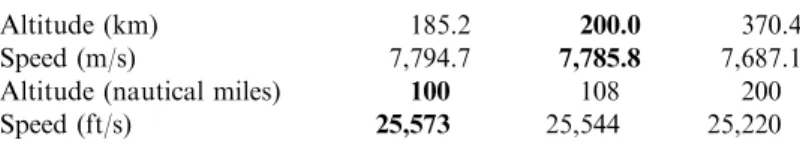
Using the Earth's equatorial radius, with the magnitude of the velocity V ¼25;947 ft/s (7,908.7 m/s), the normal (perpendicular) acceleration is equal in magnitude to the acceleration to gravity, but acts in the opposite direction . The scale of the MIRLIN (Mid-Infrared Large Well Imager) is indicated by a light-year bar.
THE CHALLENGE
During that nearly thirty-year period, the countries of the former Soviet Union (USSR) launched a series of Salyut orbital stations, culminating in MIR, Russia's seventh orbital station. Missions must be conducted within the project team's possible lifetime, i.e. approximately twenty Earth years.
THE CHALLENGE OF FLYING TO SPACE
Even the Russian Buran had a lower sliding angle of attack than a rocket plane. Most of the reduction in gross weight is due to the lower amount of oxidizer and the lower weight of the propulsion system.
OPERATIONAL REQUIREMENTS
So now it is for the future to achieve the dreams of the previous generation. In 50 years since the first artificial satellite (Sputnik), the launch vehicle is still the liquid rocket-propelled ballistic missile of the late 1950s.
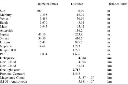
OPERATIONAL SPACE DISTANCES, SPEED, AND TIMES
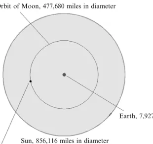
From the Sun, we can continue outward to the outer edge of our solar system and our nearest star, Proxima Centauri. The second zone extends to the boundary of our solar system and the galactic medium, the Heliopause.
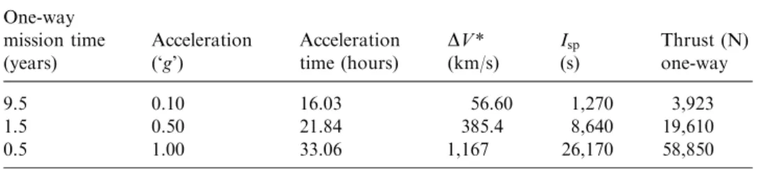
IMPLIED PROPULSION PERFORMANCE
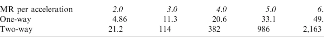
The challenge is greater for a two-way mission and involves maintaining the propellant after a long stay in the space environment. We have not yet said anything about the performance of the propulsion system (in terms of its ISP), we only estimated a reasonable value for the mass ratio required to move the spacecraft from LEO and to its destination distant space.
PROPULSION CONCEPTS AVAILABLE FOR SOLAR SYSTEM EXPLORATIONSYSTEM EXPLORATION
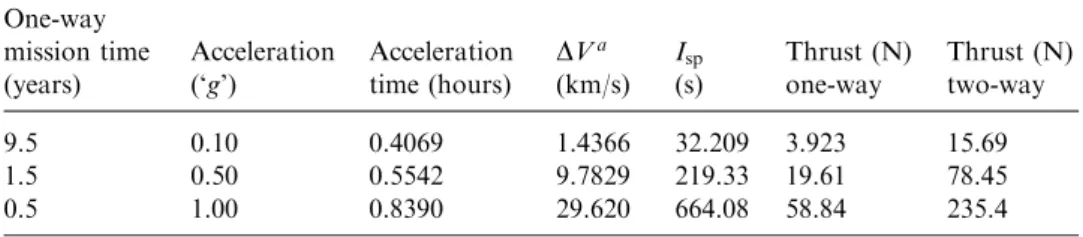
Keep in mind, however, that these times are for observers on Earth, not for the spacecraft crew. The available thrust level is extremely small and decreases with the square of the distance from the sun.
BIBLIOGRAPHY
This propulsion concept, which has been widely publicized recently, is certainly capable of doing Solar System missions, but the poor thrust at this time and in the foreseeable future, as in the case of the solar sail concept, makes it unable to not meet the travel time criterion. As mentioned, these propulsion systems limit us to our Solar System and long duration missions (10 years or more to Pluto).
MEETING THE CHALLENGE
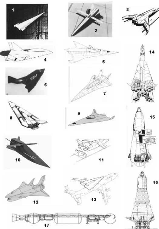
The rocket engine for the X-15 was developed from previous rockets and developed to a level not yet installed in an aircraft. The goal of the X-15 was an approach to fly to space as many times as could be expected from an aircraft-launched experimental vehicle.
EARLY PROGRESS IN SPACE
Deep space exploration and the creation of a permanent lunar base was also part of the overall space plan (see Chapter 6). Deep space exploration and the creation of a permanent lunar base was also part of the overall space plan.

HISTORICAL ANALOGUES
After NASA submitted the three operational shuttles, the Soviets were convinced that ''the missing four''. The neural network controller, without any input from ground control, performed a 540-degree turn, rather than the planned 180-degree turn, to bleed off the excessive speed [Lozino-Lozinski, 1990].
CONFLICTS BETWEEN EXPENDABLE ROCKETS AND REUSABLE AIRBREATHERS
A combined-cycle propulsion system, in which a single propulsion system can switch from one mode to another, is the key to the success of an air-breathing launcher. In this case, the fuselage of the An-225 can carry part of the launch crew and equipment.

COMMERCIAL NEAR-EARTH LAUNCHERS ENABLE THE FIRST STEP
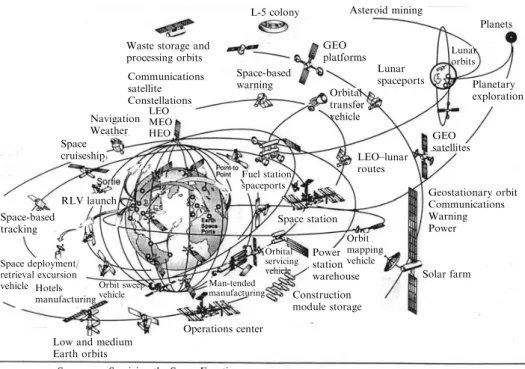
A US view of future space infrastructure making full use of the space potential of Dr. William Gaubatz, when he was director of the McDonnell Douglas Astronautics Delta Clipper Program, circa 1999. The Space Cruiser is a LEO service vehicle capable of using of the filling station shown in Figure 5.27. .
BIBLIOGRAPHY
Note that in Figure 3.3 the mass ratio curve is essentially continuous, with an abrupt decrease around Mach 5. Based on the definition of fuel weight to OWE in equations (3.1), the values from Figure 3.3 result in a fuel weight to weight ratio OWE. of about 1.
OPERATIONAL CONCEPTS ANTICIPATED FOR FUTURE MISSIONSFUTURE MISSIONS
If that payload represents a 14% fraction of the launcher's empty weight, then the launcher's empty weight is 114.3 tons and, with the typical mass ratio to reach LEO of 8.1 for an all rocket system, the total mass at liftoff is 925.7 ton. If that payload represents a 14% fraction of the launcher's empty weight, then the launcher's empty weight is 70.0 tons.
CONFIGURATION CONCEPTS
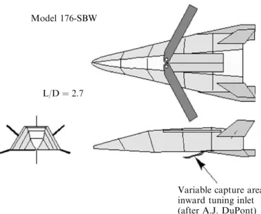
As shown in Figure 3.9, the propellant volume is plotted for a number of geometrically related hypersonic shapes as a function of their wetted area. A McDonnell Douglas Astronautics Company Model 176 wind tunnel model installed in the McDonnell Aircraft Company Hypervelocity Impulse Tunnel for a heat transfer mapping test is shown in Figure 3.15.

TAKEOFF AND LANDING MODE
However, in some launcher studies, study directives mandate horizontal lift regardless of mass ratio. With this approach, landing and takeoff speeds are essentially equal, adding a degree of operational simplicity.
AVAILABLE SOLUTION SPACE
BIBLIOGRAPHY
It would take 64 flights a year to lift crew supplies to the station, not counting fuel and hardware replacement missions that could require another five to six flights a year. For the MOL designers of 1964, it was instead a fleet of 10 to 14 vehicles in continuous use operated over a 15-year period, plus repair and maintenance.
PROPULSION SYSTEM ALTERNATIVES
In the last paragraph of the chapter, the sentence is: "The liquid oxygen turbopump was the next component in line." A single combined cycle engine operating in all required cycle modes, throughout the flight trajectory [Maita et al., 1990;.
PROPULSION SYSTEM CHARACTERISTICS
In the case of most respiratory propulsion systems, the transition from one cycle to another is not a show stopper. For air propulsion, the two main considerations are: the flow energy compared to the energy the fuel can add to the flow through combustion, and the internal flow energy losses due to internal drag of struts, injectors and skin friction and fuel/air mixing.
AIRFLOW ENERGY ENTERING THE ENGINE
In actual combustion, 100% of the fuel energy is not available to increase airflow energy. This means that the kinetic energy of the air stream is nine times greater than the heat added by burning the fuel, which is a staggering number.

INTERNAL FLOW ENERGY LOSSES
The only positive term that adds to the available energy is the kinetic energy of the injected fuel. With this information, the magnitude of the internal engine resistance can be compared to the external aircraft resistance.

SPECTRUM OF AIRBREATHING OPERATION
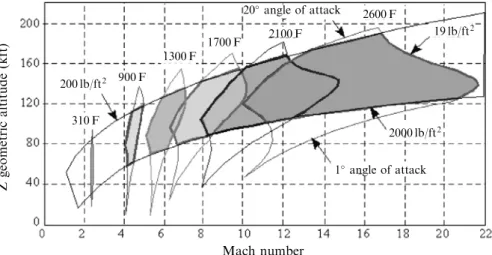
To the right of this region, the kinetic enthalpy compression ratio exceeds the value of the optimal enthalpy compression ratio. The speed regime to the right of the 4 energy ratio line is questionable for an operational vehicle.
DESIGN SPACE AVAILABLE—INTERACTION OF PROPULSION AND MATERIALS/STRUCTURESAND MATERIALS/STRUCTURES
Similarly, reducing the angle of attack to almost 1 degree of angle of attack could "overheat" the expansion surface (upper surface). In Figure 4-8, the maximum temperature of the material is 4600F (2542C) for an air-breathing vehicle cruising or accelerating to orbital speed.
MAJOR SEQUENCE OF PROPULSION CYCLES
Whether accelerating or cruising, any deviation from straight ahead can be a source of "overheating" of the thermal protection system. less the weight ratio and the oxygen-to-fuel ratio, the smaller the size and gross weight of the vehicle. In Table 4.4, the term ''Abortable at launch'' is the ability of the launcher to safely abort the mission while on launch and to return to the launch site.
ROCKET-DERIVED PROPULSION
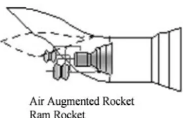
Since the thrust per unit mass flow is constant, the rocket motor thrust is a function of the total mass flow. The external air stream is mixed with the rocket exhaust to increase mass flow and with the combustion of the excess fuel thrust and specific impulse increase at lower Mach numbers (M<6).
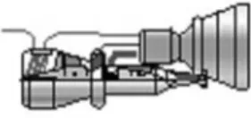
AIRBREATHING ROCKET PROPULSION
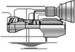
The total thermal energy collected from the incoming air and hydrogen combustion chamber is used to drive an expansion turbine, which in turn drives a turbopump that pumps liquid air into the rocket motor. The turbopump pressurizes the liquid air to the rocket's working pressure so that it can be introduced into the rocket's combustion chamber.
ENGINE THERMAL INTEGRATION
When these principles are applied to SSTO and TSTO launchers, size and weight are reduced (both dry and gross weight). These three propulsion systems can profoundly affect the size and weight of both SSTO and TSTO launchers if applied.
TOTAL SYSTEM THERMAL INTEGRATION
The result was an experiment that used a test section of a high-temperature hypersonic tunnel as a scramjet combustion engine. The model was mounted on the injection system so that the duration of time on the test section could be controlled.

THERMALLY INTEGRATED ENRICHED AIR COMBINED CYCLE PROPULSIONCYCLE PROPULSION
The oxygen component is then stored for use in the rocket takeoff portion of the flight. The oxygen component is then liquefied as LEA (LEA contains 80% to 90% oxygen) and stored for use in the rocket takeoff portion of the flight.
COMPARISON OF CONTINUOUS OPERATION CYCLES
The air-breathing thrust cycles down to the right, lowering the weight ratio and oxidizer-to-fuel ratio to values of 2.5 and 0.5, respectively. So the fuel-to-OWE ratio is multiplied by one plus the oxidizer-to-fuel ratio to produce the weight ratio.
WREOWE ¼ OWE
CONCLUSIONS WITH RESPECT TO PULSE DETONATION CYCLESDETONATION CYCLES
With these considerations, the OWE of 70 metric tons is equivalent to the conventional missile. For other propulsion systems the OWE is 70 tonnes plus any differential weight for the propulsion system.
COMPARISON OF CONTINUOUS OPERATION AND PULSED CYCLESPULSED CYCLES
The weight ratio, i.e. the gross take-off weight, is a direct result of the propellant weight relative to the OWE.
WR = OWE ¼ OWE
LAUNCHER SIZING WITH DIFFERENT PROPULSION SYSTEMS The real measure of a propulsion system’s performance is when, installed in a vehicle
All weight ratios presented in this chapter include the orbital maneuvering weight ratio of 1.1148, assumed constant for all propulsion systems. In these cases, the decisive structural parameter was the thermal strength and stiffness of the material.

STRUCTURAL CONCEPT AND STRUCTURAL INDEX, ISTR
The aerodynamic surface is made by smooth shingles with interlocking shingles with standoff and insulation materials that provide a high-temperature radiating surface to dissipate most of the incoming aerodynamic heating to space. Depending on the duration of the flight, that heat can be absorbed in the airframe's thermal capacitor or removed by an active thermal management system (Figures 4.17 and 4.18).
SIZING RESULTS FOR CONTINUOUS AND PULSE DETONATION ENGINESDETONATION ENGINES
The ram rocket, in which oxygen is burned in the secondary air of the ejector, is a different case, and the weight and oxidizer in the propellant are smaller than all rockets. Direct air-breathing rockets (LACE, deep-cooled rocket, or KLIN cycle) form a cluster in the center of each graph, in the 3 to 4 oxidizer to fuel ratio and the 5.5 to 6.5 weight ratio zone .