Ronald Schrimpf for their profound support during my time at Vanderbilt University and during the writing of this dissertation. Having the opportunity to study at Vanderbilt University and complete the graduate program was very rewarding for me. Synchronization is achieved because the leading edge of the comparator 2 output signal goes to logic one and the trailing edge goes to logic zero before the leading edge and trailing edge of the one-shot timer/slow start output signal.
42 Figure 21: Application example of a boost converter with the controller's new hysteretic-based feedback loop built from common off-the-shelf components. 46 Figure 25: Output voltages of one-shot timer/slow start, comparator 2 and power switch drive versus time in PSM. 47 Figure 26: Output voltages of one-shot timer/slow start and comparator 2 vs. time at an input voltage of 10 V and an output power of 100 W.
49 Figure 28: Output voltages for one-shot timer/slow start and comparator 2 vs. time in PSM at an input voltage of 14V and output power of 2W.
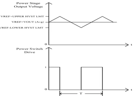
Its change in switching frequency is the main practical drawback of hysteretic topology in its basic form. This is because the switching frequency is not determined by any clock or synchronization signal. This thesis identifies the main problem with traditional PWM controllers, discusses previous work on hysteretic controllers, describes in detail a new controller resulting from the combination of a pure hysteresis controller with a traditional PWM controller, analyzes the modes of operation supported by this new controller, and illustrates the new controller based on hysteresis with SPICE simulation and prototype results.
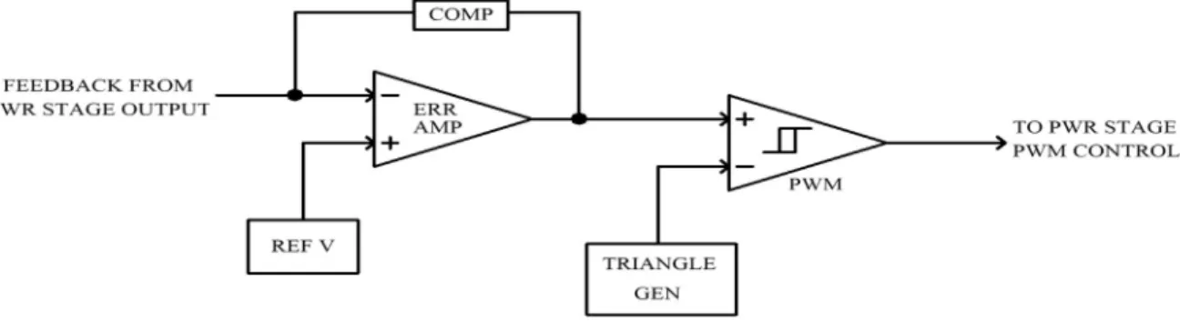
The problem becomes even more pronounced if the change occurs on the input side of the power stage. The minimum, 2-pole low-pass filter is usually used at the output of the power stage making the design of the compensation network for VMC a complex process [4]. Compensation is also complicated due to the 2-pole low-pass filter commonly used at the output of the power stage.
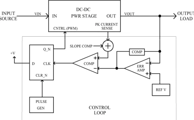
A logic zero on the PWM control line directs the power stage to not output current. In CMC, the 2-pole low-pass filter typically used at the output of the power stage is driven by an effective current source. CMC can rectify the output of the power stage with greater speed than VMC, but adding a compensation network to the error amplifier adds delay in the feedback loop.
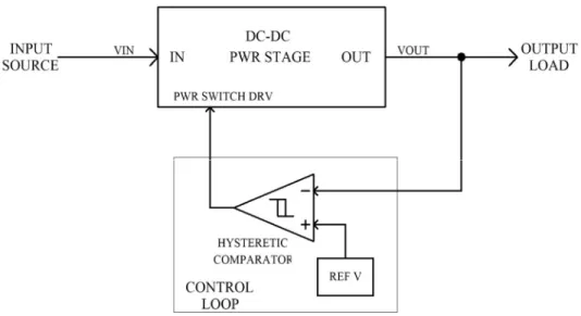
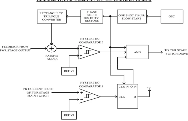
Switching between two hysteresis thresholds set by the hysteretic comparator allows the output of the power stage to be adjusted [6]. The output voltage of the power stage is fed back to the DCS control circuit via two separate inputs.
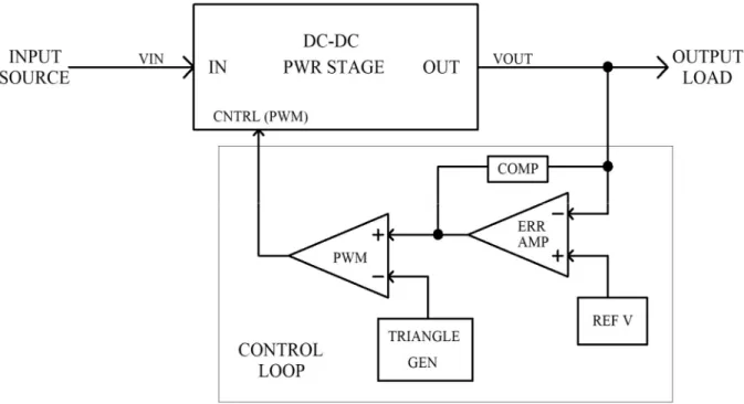
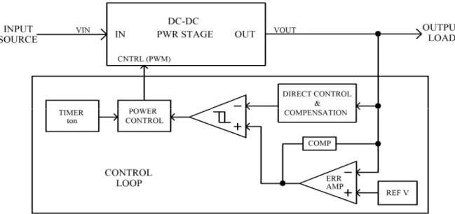
All compensation components have been moved out of the feedback loop and into the power stage if necessary. This allows for a much faster loop response since the only delay is the propagation delay of the hysteretic comparator [10]. To achieve accurate tracking and control of the output variable in the power stage, a high open loop gain is necessary.
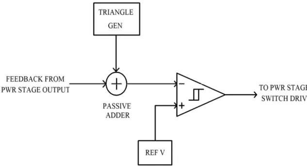
The gain through the hysteretic comparator is controlled directly by the amplitude of the triangular waveform supplied to the negative terminal. Because the output of the hysteretic comparator directly drives the power switches in the power stage, via a gate driver, the excessive jitter will propagate to the power stage, resulting in audible noise emanating from. One shot timer/slow start: Provides a gradual increase in the output voltage of the output stage and sets the maximum duty cycle requirement for the converter.
This function block also restores the one-shot timer output to a 50% duty cycle before sending it to the rectangle-to-triangle converter. The amplitude of the output signal from this block sets the gain of the hysteretic comparator for use in PWM mode. Together with the power stage gain, sets the open loop gain of the entire system.
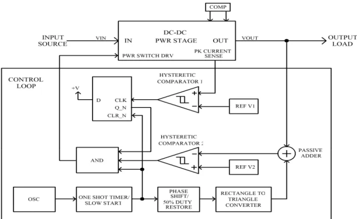
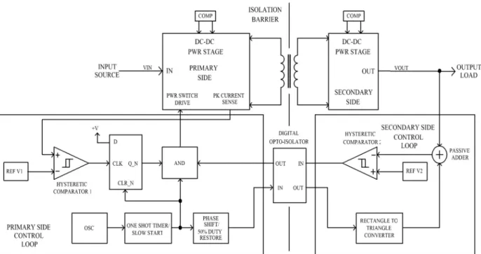
Hysteretic Comparator 1 and D-Latch: Provides peak current monitoring in the power phase for current limiting. AND function: Combines the signal outputs of the one-shot timer, hysteretic comparator 2 and D-Latch to provide full control over the DC-DC converter. Because the feedback signal from hysteretic comparator 2 consists of pulses, a digital opto-isolator is required instead of the traditional analog version typically found in isolated DC-DC converters.
This low-pass filter attenuates the output ripple of the power stage, depending on the effective cutoff frequency of the RC network. The delta generator effectively "sees" a high-pass network, since the output impedance of the power stage is designed with low impedance. The net effect of the RC network is attenuation of the output ripple of the power stage, while the output of the triangle generator passes with minimal attenuation and phase shift [10].
Gain Derivation
An application example is presented and discussed for the new hysteretic-based controller with a prototype boost converter demonstrating the results of the SPICE simulations. The intent of this chapter is not to provide detailed methodology for the design of the boost power stage or why certain component and parameter values were chosen, but rather to illustrate the operation of the new hysteretic-based controller. The on-time of the one-shot timer/slow start block must be set higher than the calculated 77.78% so that comparator 2 can regulate the output voltage when delivering 100 W of output power at an input voltage of 10 V.
Since a maximum duty cycle limit is not required for this design application, setting the maximum time of the one shot timer/slow start block to a value greater than 7.78uS will allow comparator 2 to regulate the output during worst case conditions. The D latch is reset each cycle by the output signal from the one shot timer/slow start block. Synchronization is achieved when the output signal leading edge of comparator 2 sets to logic one and the trailing edge to logic zero before the leading and trailing edge of the one-shot timer/slow start block output signal.
Derivation of the component values for the various sections of the feedback loop will not be discussed and is left to the reader to derive. Industry standard TLC556C dual CMOS timers used as one-shot timer/slow start and 50% duty recovery functions. When triggered, the component values used result in a constant output pulse on time of 8.23uS for the one-shot timer/slow start and 5.03uS for the 50% duty recovery timers.
Texas Instruments 74HC74 double D-type latch is used to implement part of the cycle-by-cycle current limit portion of the loop.
Available: https://www.electronicdesign.com/power-management/article/21798877/voltagemode-hysteretic-or-hystereticbased-welke-to-choose. Available: https://www.microsemi.com/document-portal/doc_view/124786-voltage-mode-current-mode-and-hysteretic-control.