Preliminary Remarks
The International Society for Photogrammetry and Remote Sensing (ISPRS) is a non-governmental organization dedicated to the advancement of photogrammetry and remote sensing and their applications. Members are national associations representing photogrammetry and remote sensing professionals and specialists of a country.
Definitions, Processes and Products
Data Acquisition
This is achieved without physical contact with the objects, which is essentially the most obvious difference from surveying. As shown in Table 1.1, the remotely sensed objects can range from planets to parts of the Earth's surface, to industrial parts, historic buildings or human bodies.
Photogrammetric Products
The most popular form for representing parts of the earth's surface is the DEM (Digital Elevation Model).
Photogrammetric Procedures and Instruments
Stating explicit information means identifying and extracting those features that must be presented on the map. An astereo plotting instrument, or stereo plotter for short, is used to measure the 3-D positions of points in a stereo model.
Historical Background
- Introduction
- Components of Aerial Cameras
- Image Motion
- Camera Calibration
- Summary of Interior Orientation
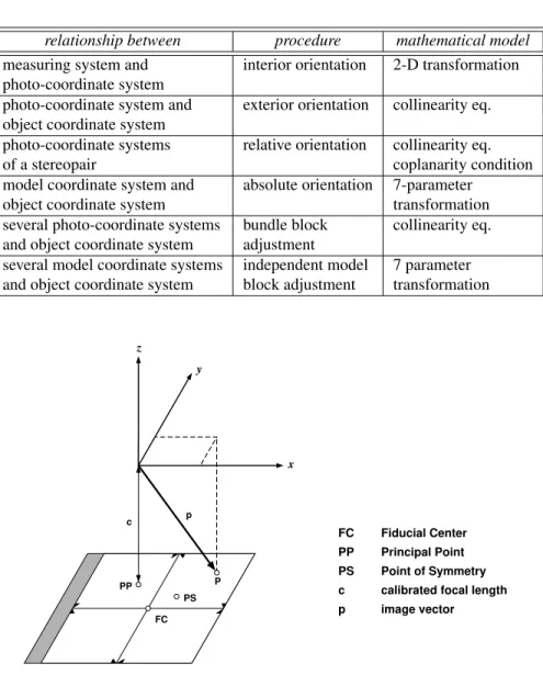
The processed plate is measured and the position of the PPA is determined in relation to the trust marks. The position of the PPA and PPS is established with reference to the fiduciary system.

Photographic Processes
- Photographic Material
- Photographic Processes
- Sensitometry
- Speed
- Resolving Power
The size and density of the silver halide crystals suspended in the gelatin emulsion varies. Image quality is directly related to the size and distribution of silver halide crystals and dyes suspended in the emulsion.

Overview
- Camera Overview
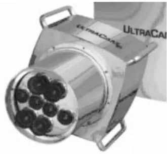
- Multiple frame cameras
- Line cameras
- Camera Electronics
- Signal Transmission
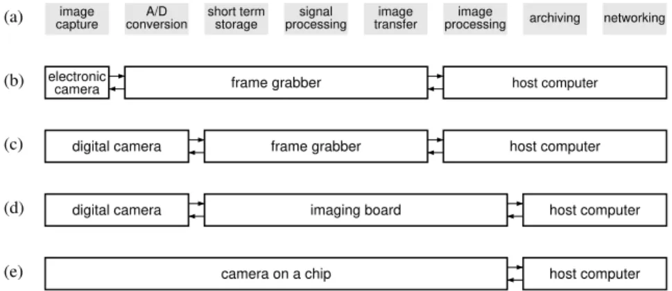
- Frame Grabbers
The accuracy of a solid-state camera depends largely on the accuracy and stability of the sensor elements, for example on the uniformity of the distance between the sensor elements and the flatness of the array. Camera calibration and measurements of the position and distance of the sensor elements confirm that the regularity is between 1/50 and 1/100 of the distance. The dark current can be measured and subtracted, leaving only the noise signal component; defective pixels can be identified and an interpolated signal can be output; the contrast can be changed (gamma correction); and image compression can be applied.
The camera electronics may have additional components that serve the purpose of increasing the camera's functionality. An example is the acceptance of external synchronization which allows the camera to be synchronized with other devices. In (a), 3 sensor lines are mounted on the image plane in front, bottom and back locations.
Frame grabbers receive the video signal, convert it, buffer data and output it to the digital image storage device.
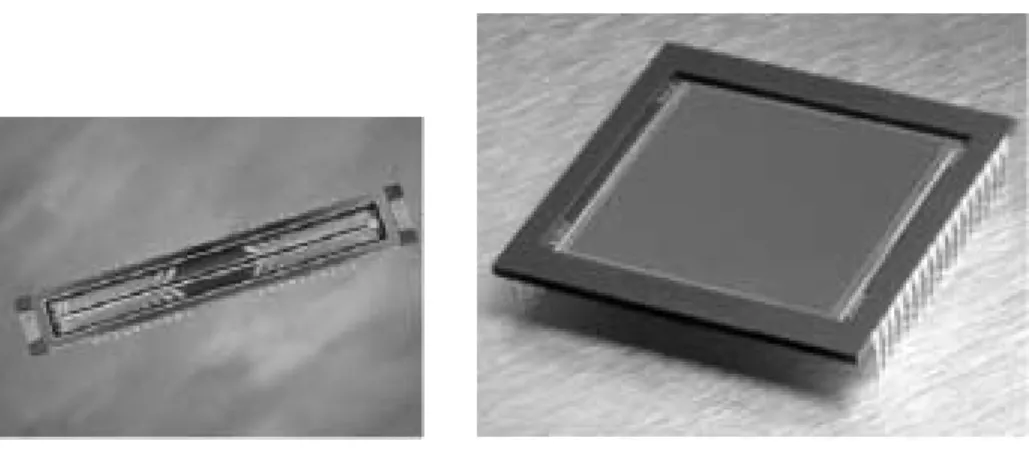
CCD Sensors: Working Principle and Properties
Working Principle
In this way, a region (depletion region) without a positive charge is formed under the electrode on the opposite side of the insulator. In (a), a photon with energy greater than the semiconductor's bandwidth creates an electron-hole pair. The electron e is attracted by the positive voltage of the electrode, while the moving hole moves towards the ground.
Photons with an energy greater than the band gap energy of the semiconductor can be absorbed in the depletion region, creating an electron-hole pair. The electron—referred to as the photon electron—is attracted to the positive charge of the metal electrode and remains in the depletion region while the moving hole moves toward the electrical ground. Note that the current charge is proportional to the number of photons absorbed under the electrode.
The initial location of the pixel whose charge is being measured in the drain is directly related to the time at which a voltage pulse was applied.
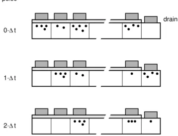
Charge Transfer
The accumulated charge is transferred during one pixel clock from the active detectors to the adjacent shift registers, from which it is read out sequentially. In front of each pixel is a lens that directs the light incident on an area defined by adjacent active pixels to the (smaller) pixel.
Spectral Response
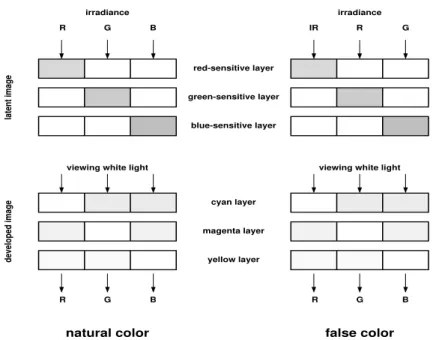
Front-illuminated sensors have a lower quantum efficiency than back-illuminated sensors because part of the incident flux can be absorbed or redirected by the electrodes (see text for details). The photo is the end result of the data acquisition process discussed in the previous chapter. Of greatest importance for measurement and interpretation are the positive reproductions of the negatives, called diapositives.
In this chapter we describe the types of aerial photographs, their geometrical characteristics and relationship to object space.

Classification of aerial photographs
Orientation of camera axis
Here we present the terminology used to classify aerial photographs according to camera axis orientation. Gyroscopically controlled mounts ensure camera stability so that tilt is typically less than two to three degrees. A schematic diagram of a true vertical photograph is shown in (a); (b) shows a low slope and (c) depicts a high slope picture.
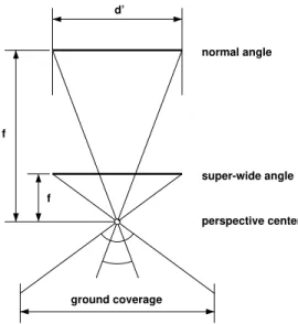
Angular coverage
Emulsion type
Geometric properties of aerial photographs
- Definitions
- Image and object space
- Photo scale
- Relief displacement
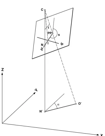
It is the azimuth of the principal plane trace in the XY plane of the earth system. The main line is directed in the direction of the maximum slope of the tilted photo. The horizon line is in the scope of the photo only for high-angle photos.
The principal rays of each bundle of all object points pass through the center of the entrance and exit pupil, unchanged in direction. This causes two problems: geometric reconstruction (eg the position of objects) and radiometric reconstruction (eg the gray shades of a surface). By partial reconstruction we mean that only a fraction of the information recorded from the object space is used for its representation.
Table 5.1 summarizes the most common relationships, along with associated photogrammetric procedures and basic mathematical models.
Coordinate Systems
Photo-Coordinate System
In this chapter we describe these procedures and the mathematical models, with the exception of aerotriangulation (block fitting), which will be discussed later. They differ mainly in the degree of complexity, that is, how accurately they describe physical processes. For example, a similarity transformation is a good approximation to describe the process of converting measured coordinates to photo coordinates.
Object Space Coordinate Systems
Interior Orientation
- Similarity Transformation
- Affine Transformation
- Correction for Radial Distortion
- Correction for Refraction
- Correction for Earth Curvature
- Summary of Computing Photo-Coordinates
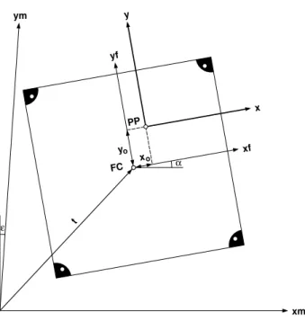
Thus, the calculation of internal orientation parameters is the same as the measurement of reference points (in the measurement system). Since the origin of the photo-coordinate system is known in the fiducial system (x0, y0), the photo-coordinates are easily obtained by translation. Radial distortion can also be represented by an odd power polynomial of the form.
Strictly speaking, the correction of photo coordinates due to earth curvature is not a refinement of the mathematical model. It would be quite awkward to produce the map in the Cartesian system and then transform it to the target system. Insert the slide into the measuring system (eg comparator, analytical plotter) and measure the fiducial marks in the machine coordinate system xm, ym.
Since this correction has the opposite sign of the refraction, the combined correction for refraction and soil curvature would bedcomb= 31µm.
Exterior Orientation
Single Photo Resection
The position and position of the camera in relation to the coordinate system of the object (external orientation of the camera) can be determined with the help of collinearity equations. Thus, the collinearity equations can be directly used as observation equations, as the following functional representation illustrates. If three control points are measured, a total of 6 equations are formed to solve for the 6 external orientation parameters.
Computing Photo Coordinates
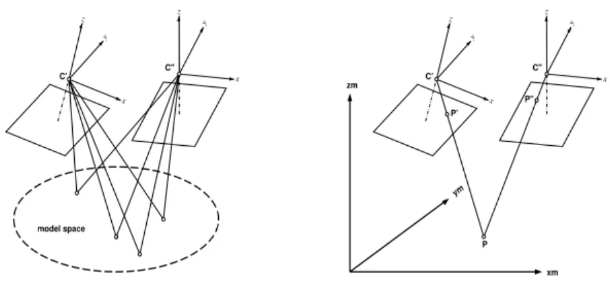
Orientation of a Stereopair
- Model Space, Model Coordinate System
- Dependent Relative Orientation
- Independent Relative Orientation
- Direct Orientation
- Absolute Orientation
- Background
- System Overview
- Basic Functionality
- Typical Workflow
- Advantages of Analytical Plotters
As already mentioned, the definition of the coordinate system of the model reduces the number of parameters by seven. The definition of the model coordinate system in the case of dependent relative orientation is shown in the figure. This step means introducing the external orientation of the photo-coordinate system, as it is known.
With this definition of the model coordinate system, we are left with the following functional model. With this definition of the model coordinate system, we have eliminated the position of both perspective centers and one rotation angle. For example, the rotation angles φ′, κ′ can be calculated based on the spatial direction of the base in the dependent relative orientation.
It is good practice to include control points in relative orientation measurements and calculations.
Digital Photogrammetric Workstations
Background
Great advances have been made in digital photogrammetry over the past few years due to the availability of new hardware and software, such as powerful image processing workstations and significantly increased storage capacity. On the input side, we have a digital camera or a scanner with which existing aerial photos are digitized. The view presented here is that a DPW is a separate, unique part of a digital photogrammetric system.
The accuracy of digital photogrammetry products depends largely on the accuracy of electronic cameras or scanners and on the algorithms used. Unlike analytical plotters (and even more so for analog stereoplotters), the hardware in DPWs has no appreciable effect on accuracy. The main feature of Intergraph's ImageStation Z is the 28-inch panoramic monitor that provides a large field of view for stereo viewing (see Fig. 6.9, label 1).
The infrared radiator on top of the monitor (label 4) provides synchronization of the glasses and allows group viewing.
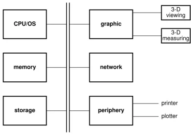
Basic System Components
As an option to the 3-D pointing device (tracking ball), the system can be equipped with hand wheels to more closely simulate the operation on a classic instrument. UNIX satisfies these needs; in fact, UNIX-based workstations were the systems of choice for DPWs until the advent of Windows 95 and NT making PCs a serious competitor to UNIX-based workstations. The purpose of the display processor is to retrieve data, such as raster (images) or vector data (GIS), process it and store it in the display memory and update the monitor.
It is often linked to the scanning system and other workstations, such as a geographic information system.

Basic System Functionality
As a result, the size of the image being viewed decreases and stereoscopic viewing may be affected. As pointed out earlier, using more monitor pixels for displaying an image pixel reduces the size of the field of view. Here, the left and right images are displayed on the left and right half of the monitor, respectively.
In the simpler solution, the cursor moves on the screen according to the movements of the pointing device (eg mouse) by the operator. This is similar to the operation of analytical plotters where the floating point mark is always in the center of the field of view. The display memory contains the portion of the image that is displayed on the monitor.
As soon as we roam out of display memory, new image data must be fetched from disk and transferred to the graphics system.
Analytical Plotters vs. DPWs