PROJECT : - DONGGI SENORO
CLIENT :- DONGGI SENORO
PT. SCHNEIDER E-HOUSE INDONESIA
I. Lightning Risk Assessment L.1 General
This lightning risk assessment methodology is provided to assist the building owner, safety professional, or architect/engineer in determining the risk of damage or injury due to lightning. This annex provides a simplified, quicklook assessment (Section L.5) and a more detailed assessment for those requiring a more detailed analysis (Section L.6). Once the level of risk has been determined, the development of appropriate lightning protection measures can begin.
L.1.1 There are some cases where the need for protection should be given serious consideration regardless of the outcome of the risk assessment. Examples are those applications where the following are factors:
(1) Large crowds
(2) Continuity of critical services (3) High lightning flash frequency (4) Tall isolated structure
(5) Building containing explosive or flammable materials (6) Building containing irreplaceable cultural heritage
L.1.1.1 Statutory, regulatory, and insurance requirements for the installation of a lightning protection system should take precedence over the results of a risk assessment.
L.1.2 The vulnerability of a structure or object to lightning involves evaluation of the equivalent collection area of the structure or object and the flash density for the area in which the structure is located.
L.1.3 This risk assessment method is a guide that takes into account the lightning threat parameters and the following factors:
(1) Building environment (2) Type of construction (3) Structure occupancy (4) Structure contents
(5) Lightning stroke consequences
L.1.4 Lightning risk for a structure is the product of the lightning frequency, exposure vulnerability, and the consequence of the strike to the structure or object L.2 Lightning Flash Density (Ng). Lightning flash density, the yearly number of flashes to ground per square kilometer, can be found in Figure below
flash density in strikes to ground per kilometre square per year as per Furse Strike Risk Software V5.0
L.3 Annual Threat of Occurrence (Nd). The yearly annual threat of occurrence (lightning strike frequency) (Nd) to a structure is determined by the following equation:
where:
includes the effect of the height and location of the structure.
L.4.1 The equivalent ground collection area of a structure is the area obtained by extending a line with a slope of 1 to 3 from the top of the structure to ground completely around the structure. The equivalent collection area can be developed either numerically or by graphical methods.
L.4.1.1 The equivalent collection area of a rectangular structure with length L, width W, and height H (see Figure L.4.1.1) is as follows:
L.4.1.2 The equivalent collection area of complex structures can be developed by numerical or graphical methods. [See Figure L.4.1.2(a) and Figure L.4.1.2(b) for examples of complex structures.]
L.4.2 The location factor accounts for the topography of the site of the structure and any objects located within the distance 3H from the structure that can affect the collection area. Location factors are given in Table L.4.2.
Nd=(Ng)(Ae)(C1)(10-6) = Potential events/ yr
Nd = yearly lightning strike frequency to the structure or object Ng = lightning ground flash density in flashes/km2/year Ae = the equivalent collection area of the structure (m2) C1 = environmental coefficient
L.4 Equivalent Collection Area (Ae).
Ae refers to the equivalent ground area having the equivalent lightning flash vulnerability as the structure. It is an area adjusted for the structure that
Ae = LW+6H (L+W)+9H2
L.4.3 Where the equivalent collection area of one structure or object totally encompasses another structure, the covered structure is disregarded L.4.4 When the collection areas of several structures overlap, the corresponding common collection area is considered as a single collection area.
L.5 Simplified Risk Assessment.
L.5.1 General.
L.5.1.1 A simplified risk assessment calculates the tolerable lightning frequency (Nc) and compares it to the annual threat of occurrence (Nd) calculated according to Section L.3. The tolerable lightning frequency (Nc) is a measure of the risk of damage to the structure, including factors affecting risks to
the structure, to the contents, and of environmental loss. It is losses by various coefficients relating to the structure, the contents, and the consequence of damage.
The tolerable lightning frequency is expressed by the following formula
L.5.2 Risk Calculation
L.5.2.1 The tolerable lightning frequency (Nc) is compared with the annual threat occurrence (Nd). The result of this comparison is used to decide if a lightning protection system is needed. If Nd ≤ Nc , a lightning protection system can be optional. If Nd > Nc , it is recommended that a lightning protection
system be installed.
DONGGI SENORO DONGGI SENORO
PT. SCHNEIDER E-HOUSE INDONESIA
This lightning risk assessment methodology is provided to assist the building owner, safety professional, or architect/engineer in determining the risk of damage or injury due to lightning. This annex provides a simplified, quicklook assessment (Section L.5) and a more detailed assessment for those requiring a more detailed analysis (Section L.6). Once the level of risk has been determined, the development of appropriate lightning protection measures can begin.
L.1.1 There are some cases where the need for protection should be given serious consideration regardless of the outcome of the risk assessment. Examples
L.1.1.1 Statutory, regulatory, and insurance requirements for the installation of a lightning protection system should take precedence over the results of a risk
L.1.2 The vulnerability of a structure or object to lightning involves evaluation of the equivalent collection area of the structure or object and the flash density for
L.1.3 This risk assessment method is a guide that takes into account the lightning threat parameters and the following factors:
L.1.4 Lightning risk for a structure is the product of the lightning frequency, exposure vulnerability, and the consequence of the strike to the structure or object L.2 Lightning Flash Density (Ng). Lightning flash density, the yearly number of flashes to ground per square kilometer, can be found in Figure below
flash density in strikes to ground per kilometre square per year as per Furse Strike Risk Software V5.0
L.3 Annual Threat of Occurrence (Nd). The yearly annual threat of occurrence (lightning strike frequency) (Nd) to a structure is determined by the following
L.4.1 The equivalent ground collection area of a structure is the area obtained by extending a line with a slope of 1 to 3 from the top of the structure to ground completely around the structure. The equivalent collection area can be developed either numerically or by graphical methods.
L.4.1.1 The equivalent collection area of a rectangular structure with length L, width W, and height H (see Figure L.4.1.1) is as follows:
L.4.1.2 The equivalent collection area of complex structures can be developed by numerical or graphical methods. [See Figure L.4.1.2(a) and Figure L.4.1.2(b)
L.4.2 The location factor accounts for the topography of the site of the structure and any objects located within the distance 3H from the structure that can refers to the equivalent ground area having the equivalent lightning flash vulnerability as the structure. It is an area adjusted for the structure that
L.4.3 Where the equivalent collection area of one structure or object totally encompasses another structure, the covered structure is disregarded L.4.4 When the collection areas of several structures overlap, the corresponding common collection area is considered as a single collection area.
L.5.1.1 A simplified risk assessment calculates the tolerable lightning frequency (Nc) and compares it to the annual threat of occurrence (Nd) calculated according to Section L.3. The tolerable lightning frequency (Nc) is a measure of the risk of damage to the structure, including factors affecting risks to
L.5.2.1 The tolerable lightning frequency (Nc) is compared with the annual threat occurrence (Nd). The result of this comparison is used to decide if a lightning protection system is needed. If Nd ≤ Nc , a lightning protection system can be optional. If Nd > Nc , it is recommended that a lightning protection
PROJECT : - DONGGI SENORO
CLIENT :- DONGGI SENORO
PT. SCHNEIDER E-HOUSE INDONESIA
LIGHTNING PROTECTION CALCULATION FOR E-HOUSE METALCLAD SUBSTATION ( REFERENCE : NFPA 780 )
Description / Parameter Symbol / Formula / References A) CHECK FOR NEED OF PROVIDING LIGHTNING PROTECTION
i) Input Data :-
a) Dimensions of Building / Structure
Length of the Building L
( Refer the Relevant Layout Drawings of the Building / Structure )
Width of the Building W
Height of the Building H
b) 4.Isolated structure on a hilltop
1.Metal Structure, Metal Roof 1.Low value and nonflammable 2.Normally Occupied
1.Continuity of facility services not required no environmental impact c) Lightning Flash Density (Ng). Ng The yearly number of flashes to ground per km²
ii) Calculations :- Based on Tabel 1.5.2.2. Simplified Risk Calculation, NFPA 780, 2014 Collection area of a rectangular structure Ae =
Expected annual threat occurrence Nd =
Tolerable lightning frequency to the structure Nc =
Risk Calculation Result =
Calculations
Base Area of Structure Ab =
Perimeter of Structure P =
i)
a) Number of Down Conductors Required =
ii)
b) Based on Base Area of Structure:-
Number of Down Conductors Required =
c) Based on Parimeter of Structure:-
Number of Down Conductors Required =
Note:
Hence, Required Number of Down Conductors
Date
R0 9-Jun-15
Relative Structure Location (C1) C1
Determination of Construction Coefficient (C2) C2 Determination of Structure Contents Coefficient (C3) C3 Determinaton of Structure Occupancy Coefficient (C4) C4 Determinaton of Lightning Consequence Coefficient (C5) C5
B) CHECK FOR ADEQUACY OF NUMBER OF DOWN CONDUCTORS (Applicable if Provision for Lightning Protection is needed)
For Base Area (Ab) < 100m2 For Base Area (Ab) > 100m2
REVISION DETAILS Rev
.
REVISION DETAILS
DONGGI SENORO DONGGI SENORO
PT. SCHNEIDER E-HOUSE INDONESIA
LIGHTNING PROTECTION CALCULATION FOR E-HOUSE METALCLAD SUBSTATION ( REFERENCE : NFPA 780 )
Symbol / Formula / References Value Unit A) CHECK FOR NEED OF PROVIDING LIGHTNING PROTECTION
( Refer the Relevant Layout Drawings of the Building / Structure )
= 10.00 m
= 5.00 m
= 4.00 m
4.Isolated structure on a hilltop = 2
1.Metal Structure, Metal Roof = 0.5
1.Low value and nonflammable = 0.5
2.Normally Occupied = 1
1.Continuity of facility services not required no environmental impact = 1
The yearly number of flashes to ground per km² 6
Calculations :- Based on Tabel 1.5.2.2. Simplified Risk Calculation, NFPA 780, 2014
= 862.16
= 0.010346
= 0.006000 Events/yr LPS NEEDED
( L x W ) = 50
2(L+W) = 30 Meter
= 0.833333 Nos
1+(Ab-100)/300 = 0.833333 Nos
P/30 = 1 Nos.
Note:
= 3Nos.
Reviewed Approved flashes/km2/yr
LW+6H (L+W)+9H2 Meter2
(Ng)(Ae)(C1)(10-6) potential event
per year (1.5 x 10-03)/C
B) CHECK FOR ADEQUACY OF NUMBER OF DOWN CONDUCTORS (Applicable if Provision for Lightning Protection is needed)
Meter2
For Ab < 100m2
Table L.4.2 Location Factor, C1 C1
1.Structure located within a space containing structures or trees of the same height or taller within a distance of 3H 2.Structure surrounded by smaller structures within a distance of 3H
3.Isolated structure, no other structures located within a distance of 3H 4.Isolated structure on a hilltop
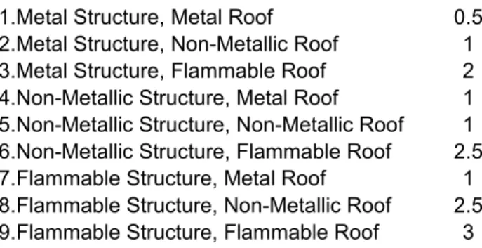
Table L.5.1.2(a) Determination of Construction Coefficient, C2 C2
0.25 1.Metal Structure, Metal Roof 0.5
0.5 2.Metal Structure, Non-Metallic Roof 1
1 3.Metal Structure, Flammable Roof 2
2 4.Non-Metallic Structure, Metal Roof 1
5.Non-Metallic Structure, Non-Metallic Roof 1 6.Non-Metallic Structure, Flammable Roof 2.5 7.Flammable Structure, Metal Roof 1 8.Flammable Structure, Non-Metallic Roof 2.5 9.Flammable Structure, Flammable Roof 3
Table L.5.1.2(b) Determination of Structure Contents Coefficient, C3 C3
1.Low value and nonflammable 0.5
2.Standard value and nonflammable 1
3.High value, moderate flammability 2
4.Exceptional value, flammable, computer or electronics 3
5.Exceptional value, irreplacable cultural items 4
Table L.5.1.2(c) Determination of Structure Occupancy Table L.5.1.2(d) Determination of Lightning Consequence
Coefficient, C4 Coefficient, C5
1.Unoccupied 0.5 1.Continuity of facility services not required no environmental imp
2.Normally Occupied 1 2.Continuity of facility services required,no environmental impact
3.Difficult to evacuate or risk of panic 3 3.Consequences to the environment
Table L.5.1.2(d) Determination of Lightning Consequence
1.Continuity of facility services not required no environmental imp 1 2.Continuity of facility services required,no environmental impact 5
3.Consequences to the environment 10
DESIGN, INSTALLATION, INSPECTION AND MAINTENANCE LIGHTNING PROTECTION SYSTEM LNG DONGGI SENORO PROJECT
BASED ON NFPA 780
CHECK LIST DESIGN, INSTALLATION, INSPECTION AND MAINTENANCE LIGHTNING PROTECTION SYSTEM
Check if Acceptable ; Provide Comment if Unacceptable Design
Chapter 4 . General Requirement
4.1 General. This chapter provides general requirements for the protection of structures against lightning 4.1.1 Material Class Requirements
4.1.1.1. Structures shall be protected according to 4.1.1.1.1 or 4.1.1.1.2.
4.1.1.1.1 Structures not exceeding 75 ft (23 m) in height shall be protected with Class I materials as shown in Table 4.1.1.1.1
4.1.1.1.2 Structures exceeding 75 ft (23 m) in height shall be protected with Class II materials as shown in Table 4.1.1.1.2.
4.1.1.2 If part of a structure exceeds 75 ft (23 m) in height (e.g., a steeple) and the remaining portion does not exceed 75 ft (23 m) in height, the requirements for Class II air terminals and conductors shall apply only to that portion exceeding 75 ft (23 m) in height.
4.2 Materials.
Protection systems shall be made of materials that are resistant to corrosion or protected against corrosion.
4.2.1 Combinations of materials that form electrolytic couples of such a nature that, in the presence of moisture, corrosion is accelerated shall not be used.
4.2.2 One or more of the materials in 4.2.2.1 through 4.2.2.3 shall be used.
4.2.2.1 Copper.
Copper shall be of the grade required for commercial electrical work and shall be of 95 percent conductivity when annealed.
4.2.2.2 Copper Alloys.
Copper alloy shall be as resistant to corrosion as is copper 4.2.2.3 Aluminum
4.2.2.3.1 Aluminum shall not be used where contact with the earth is possible or where rapid deterioration is possible 4.2.2.3.2 Conductors shall be of electrical-grade aluminum.
4.2.3 Copper lightning protection materials shall not be installed on or in contact with aluminum roofing, aluminum siding, or other aluminum surfaces
4.2.4 Aluminum lightning protection materials shall not be installed on or in contact with copper surfaces.
4.3 Corrosion Protection.
4.3.1 Protection shall be provided against deterioration of lightning protection components due to local conditions
4.3.2 Copper components installed within 24 in. (600 mm) of the top of a chimney or vent emitting corrosive gases shall be protected by a hot-dipped lead or tin coating.
4.3.3 Connectors and Fittings.
4.3.3.1 Connectors and fittings shall be compatible for use with the conductor and the surfaces on which they are installed.
4.3.3.2 Bimetallic connectors and fittings shall be used for splicing or bonding dissimilar metals.
4.4 Mechanical Damage or Displacement.
4.4.1 Any part of a lightning protection system that is subject to mechanical damage or displacement shall be protected with a protective molding or covering.
4.4.2 Where metal pipe or tubing is used around the conductor, the conductor shall be bonded to the pipe or tubing at both ends.
4.5 Use of Aluminum
Aluminum systems shall be installed in accordance with other applicable sections and 4.5.1 through 4.5.3.
4.5.1 Aluminum lightning protection equipment shall not be installed on or in direct contact with copper roofing materials or other copper surfaces, or where exposed to runoff from copper surfaces
4.5.2 Aluminum materials shall not be used within 18 in.(460 mm) of the point where the lightning protection system conductor comes into contact with the earth.
4.5.2.1 Fittings used for the connection of aluminum down conductors to copper or copper-clad grounding equipment shall be of the bimetallic type.
4.5.2.2 Bimetallic connectors shall be installed not less than 18 in. (460 mm) above earth level.
4.5.3 An aluminum conductor shall not be attached to a surface coated with alkaline-base paint, embedded in concrete or masonry, or installed in a location subject to excessive moisture.
4.6 Strike Termination Devices 4.6.1 General
4.6.1.1 Strike termination devices shall include air terminals, metal masts, permanent metal parts of structures as described in 4.6.1.4, and overhead ground wires
4.6.1.2 Combinations of these strike termination devices shall be permitted.
4.6.1.3 Strike termination devices shall be provided where required by other sections of this standard.
4.6.1.4 Metal parts of a structure that are exposed to direct lightning flashes and that have a metal thickness of 3⁄16 in. (4.8 mm) or greater shall only require connection to the lightning protection system in accordance with Section 4.8
4.6.1.5 Strike termination devices shall not be required for those parts of a structure located within a zone of protection 4.6.2 Air Terminals
The tip of an air terminal shall be not less than 10 in.(254 mm) above the object or area it is to protect, as shown in Figure 4.6.2.1
4.7.2. Location of Devices.
4.7.2.1 As shown in Figure 4.7.2.1, the distance from strike termination devices to ridge ends on pitched roofs or to edges and outside corners of flat or gently sloping roofs shall not exceed 2 ft (0.6 m).
4.7.2.2 Strike termination devices shall be placed on ridges of pitched roofs and around the perimeter of flat or gently sloping roofs at intervals not exceeding 20 ft (6 m).
4.7.2.3 Strike termination devices 2 ft (0.6 m) or more above the object or area to be protected shall be permitted to be placed at intervals not exceeding 25 ft (7.6 m).
4.7.5 Flat or Gently Sloping Roof Area.
Flat or gently sloping roofs that exceed 50 ft (15 m) in width or length shall have additional strike termination devices located at intervals not to exceed 50 ft (15 m) on the flat or gently sloping areas, as shown in Figure 4.7.5(a) and Figure 4.7.5(b); such area shall be permitted to be protected using taller strike termination devices that create zones of protection using the rolling sphere method so the sphere does not contact the flat or gently sloping roof area.
4.8 Zones of Protection.
The geometry of the structure shall determine the zone of protection
4.8.1 One or more of the following methods shall be used to determine the overall zone of protection:
(1) Air terminal placements, as described in Section 4.7 (2) The angle method, as described in 4.8.2
(3) The rolling sphere method, as described in 4.8.3 4.8.3 Rolling Sphere Method.
4.8.3.1. The zone of protection shall include the space not intruded by a rolling sphere having a radius of the striking distance determined for the type of structure being protected,as shown in Figure 4.8.3.1.
4.8.3.1.1 Where the sphere is tangent to earth and resting against a strike termination device, all space in the vertical plane between the two points of contact and under the sphere shall be considered to be in the zone of protection
4.8.3.1.2 A zone of protection shall also be formed where such a sphere is resting on two or more strike termination devices and shall include the space in the vertical plane under the sphere and between those devices, as shown in Figure 4.8.3.1
4.8.3.1.3 All possible placements of the sphere shall be considered when determining the overall zone of protection using the rolling sphere method.
4.8.3.1.4 The striking distance shall not exceed 150 ft (46 m).
4.8.3.2* For structure heights exceeding the striking distance above earth or above a lower strike termination device, the zone of protection shall be the space in the vertical plane between the points of contact and also under the sphere where the sphere is resting against a vertical surface of the structure and the lower strike termination device(s) or earth.
4.8.3.3 Under the rolling sphere method, the horizontal protected distance found geometrically by Figure A.4.8.3.1 also shall be permitted to be calculated using the following formula (units shall be consistent, ft or m)
4.8.3.3.1 For the formula to be valid, the sphere shall be either tangent to the lower roof or in contact with the earth and in contact with the vertical side of the higher portion of the structure.
4.8.3.3.2 In addition, the difference in heights between the upper and lower roofs or earth shall be the striking distance or less.
4.9 Conductors. Main conductors shall interconnect all strike termination devices and shall form two or more paths from each strike termination device downward, horizontally, or rising at no more than 1⁄4 slope to connections with grounding electrodes, except as permitted by 4.9.1 and 4.9.2
4.9.1 One-Way Path. Strike termination devices on a lower roof level that are interconnected by a conductor run from a higher roof level shall require only one horizontal or downward path to ground, provided the lower level roof conductor run does not exceed 40 ft (12 m).
4.9.2 Dead Ends. A “dead ended” main conductor shall be permitted between a single strike termination device or connector fitting and a main conductor run under the following conditions:
(1) Where the main-size conductor run to which the dead end is connected has a two-way path to ground
(2) At a main protected roof level, where the horizontal portion of the dead-end conductor is not more than 8 ft (2.4 m) in total length
(3) On a roof below the main protected roof level, where the dead-end conductor is not more than 16 ft (4.9 m) in total length, as shown in Figure 4.9.2 (4) Where all dead-end conductor runs maintain a horizontal or downward course from the strike termination device to the connection point with the main conductor run
4.9.3 Substitution of Main Conductor.
4.9.3.1 Ancillary metal parts of a structure, such as eave troughs,downspouts, ladders, chutes, or other metal parts except as permitted in 4.19.1, shall not be substituted for the main conductor.
4.9.3.2 Permanent exterior metal handrails and ladders that are subject to direct lightning strikes (e.g., on roofs or between roofs) and are electrically continuous shall be permitted to be used as main conductors where the minimum thickness is 0.064 in. (1.63 mm).
4.9.3.3 Metal roofing or siding having a thickness of less than 3⁄16 in. (4.8 mm) shall not be substituted for main conductors.
4.9.5 Conductor Bends. No bend of a conductor shall form an included angle of less than 90 degrees, nor shall it have a radius of bend less than 8 in. (203 mm), as shown in Figure 4.9.5.
4.9.6 Conductor Supports
4.9.6.1 Conductors shall be permitted to be coursed through air without support for a distance of 3 ft (0.9 m) or less.
4.9.6.2 Conductors that must be coursed through air for distances longer than that permitted in 4.9.6.1 shall be provided with a positive means of support that will prevent damage or displacement of the conductor
4.9.7 Roof Conductors
4.9.7.1 Roof conductors shall be coursed along ridges of gable, gambrel, and hip roofs; around the perimeter of flat roofs; behind or on top of parapets; and across flat or gently sloping roof areas as required to interconnect all strike termination devices
4.9.7.2 Conductors shall be coursed through or around obstructions (e.g., cupolas and ventilators) in a horizontal plane with the main conductor
4.9.8 Cross-Run Conductors. Cross-run conductors (main conductors) shall be required to interconnect the strike termination devices on flat or gently sloping roofs that exceed 50 ft (15 m) in width.
4.9.8.1 For example, roofs from 50 ft to 100 ft (15 m to 30 m) in width shall require one cross-run conductor, roofs 100 ft to 150 ft (30 m to 46 m) in width shall require two cross-run conductors, and so on.
4.9.8.2 Cross-run conductors shall be connected to the main perimeter cable at intervals not exceeding 150 ft (46 m), as shown in Figure 4.7.5(a).
4.9.9 Down Conductors.
4.9.9.1 Down conductors shall be as widely separated as practicable.
4.9.9.2 The location of down conductors shall depend on considerations such as the following:
(1) Placement of strike termination devices (2) Most direct coursing of conductors (3) Earth conditions
(4) Security against displacement (5) Location of large metallic bodies
(6) Location of underground metallic piping systems
4.9.10 Number of Down Conductors. At least two down conductors shall be provided on any kind of structure, including steeples.
4.9.10.1 Structures exceeding 250 ft (76 m) in perimeter shall have a down conductor for every 100 ft (30 m) of perimeter or fraction thereof.
4.9.10.2 The total number of down conductors on structures having flat or gently sloping roofs shall be such that the average distance between all down conductors does not exceed 100 ft (30 m).
4.9.10.3 Irregularly shaped structures shall have additional down conductors as necessary to provide a two-way path from each strike termination device.
4.9.10.4 For a flat or gently sloping roof structure, only the perimeter of the roof areas requiring protection shall be measured
4.9.10.5 When determining the perimeter of a pitched roof structure, the horizontal projection (footprint) of the protected roof shall be measured as shown in Figure 4.9.10.5.
4.9.10.6 Lower roofs or projections that are located within a zone of protection shall not be required to be included in the perimeter measurement.
4.9.11 Protecting Down Conductors. Down conductors located in runways, driveways, school playgrounds, cattle yards, public walks, or other locations subject to physical damage or displacement shall be guarded.
4.9.11.1 Metallic guards shall be bonded at each end.
4.9.11.2 The down conductor shall be protected for a minimum distance of 6 ft (1.8 m) above grade level
4.9.12. Down Conductors Entering Corrosive Soil. Down conductors entering corrosive soil shall be protected against corrosion by a protective covering beginning at a point 3 ft (0.9 m) above grade level and extending for their entire length below grade.
4.12.1 Fittings shall be attached so as to withstand a pull test of 200 lb (890 N).
4.12.2 Fittings used for required connections to metal bodies in or on a structure shall be secured to the metal body by bolting, brazing, welding, screwing, or high-compression connectors listed for the purpose.
4.12.3 Conductor connections shall be of the bolted, welded, high compression, or crimp type.
4.12.4 Crimp-type connections shall not be used with Class II conductors 4.13 Grounding Electrodes.
4.13.1 General
4.13.1.1 Each down conductor shall terminate at a grounding electrode dedicated to the lightning protection system or to a grounding electrode system in the case of a building, structure, or facility that has multiple grounding electrodes that are bonded together with a ground ring electrode sized in accordance with 4.13.4.2 to form the grounding electrode system.
4.13.1.2 The design, size, and depth of grounding electrodes shall comply with 4.13.2 through 4.13.8.
4.13.1.3 Underground metallic piping or ground rod–type electrodes for electrical, communications, or other systems shall not be used in lieu of lightning grounding electrodes
4.13.1.4 The down conductor(s) shall be attached permanently to the grounding electrode system by bolting, brazing, welding, or high-compression connectors listed
for the purpose.
4.13.1.5 Grounding electrodes shall be installed below the frost line where possible (excluding shallow topsoil conditions).
4.13.1.6* In corrosive environments, the use of stainless steel alloy grounding electrodes shall be permitted.
4.13.2* Ground Rods.
4.13.2.1 Ground rods shall be not less than 1⁄2 in. (12.7 mm) in diameter and 8 ft (2.4 m) long.
4.13.2.2 Rods shall be free of paint or other nonconductive coatings.
4.13.2.3 Ground Rod Depth
4.13.2.3.1 The ground rods shall extend vertically not less than 10 ft (3 m) into the earth
4.13.2.3.2 The earth shall be compacted and made tight against the length of the conductor and ground rod, as illustrated in Figure 4.13.2.3.2.
4.13.2.4* Multiple Ground Rods. Where multiple connected ground rods are used, the separation between any two ground rods shall be at least the sum of their driven depths, where
practicable.
4.13.2.5 Ground rods shall be copper-clad steel, solid copper, or stainless steel.
4.13.3 Concrete-Encased Electrodes. Concrete-encased electrodes shall be used only in new construction
4.13.3.1 The electrode shall be located near the bottom of a concrete foundation or footing that is in direct contact with the earth and shall be encased by not less than 2 in. (50 mm) of concrete.
4.13.3.2 The encased electrode shall consist of one of the following:
(1) Not less than 20 ft (6 m) of bare copper main-size conductor
(2) At least 20 ft (6 m) of one or more steel reinforcing bars or rods not less than 1⁄2 in. (12.7 mm) in diameter that have been effectively bonded together by either welding or overlapping 20 diameters and wire tying
4.13.4 Ground Ring Electrode. Aground ring electrode encircling a structure shall be as shown in Figure 4.13.4.
4.13.4.1 The ground ring electrode shall be in direct contact with earth at a depth of not less than 18 in. (460 mm) or encased in a concrete footing in accordance with 4.13.3
4.13.4.2 The ground ring electrode shall be a main-size (lightning) conductor or a grounding conductor of equivalent or greater cross-sectional area.
4.13.5* Radials.
4.13.5.1 A radial electrode system shall consist of one or more main-size conductors, each in a separate trench extending outward from the location of each down conductor.
4.13.5.2 Each radial electrode shall be not less than 12 ft (3.6 m) in length.
4.13.5.3 The radial electrode shall be buried not less than 18 in. (460 mm) below grade.
4.13.6* Plate Electrode or Ground Plate Electrode.
4.13.6.1 A ground plate or plate electrode shall have a minimum thickness of 0.032 in. (0.8 mm) and a minimum surface area of 2 ft2 (0.18 m2) 4.13.6.2 The ground plate electrode shall be buried not less than 18 in. (460 mm) below grade.
4.13.7 Combinations. Combinations of the grounding electrodes in Section 4.13 shall be permitted
4.13.8 Grounding Electrode Selection Criteria. The site limitations and soil conditions shall determine the selection of the type or combinations of types of grounding electrodes used.
4.13.8.1* Shallow Topsoil. The methods in 4.13.3 through 4.13.7 shall be used in shallow topsoil conditions where practicable.
4.13.8.1.1 Where the methods described in 4.13.3 through 4.13.6 are found to be impractical due to topsoil depth less than 18 in. (460 mm), it shall be permitted to provide a ground terminal buried at the maximum depth of topsoil available.
4.13.8.1.2* The ground terminal for shallow topsoil shall be either a ground ring electrode, in accordance with 4.13.4, a minimum distance of 2 ft (0.6 m) from the foundation or exterior footing; radial(s) in accordance with 4.13.5; or a plate electrode, in accordance with 4.13.6, a minimum distance of
2 ft (0.6 m) from the foundation or exterior footing. The ground ring electrode, radial(s), or plate electrode shall be buried at the maximum depth of topsoil available.
4.13.8.1.3 Where a method of 4.13.8.1.2 is impossible, radial( s) shall be permitted to be laid directly on bedrock a minimum distance of 12 ft (3.6 m) from the foundation or exterior footing. A ground ring electrode encircling the structure shall be permitted to be laid directly on bedrock a minimum distance
of 2 ft (0.6 m) from the foundation or exterior footing. 4.13.8.1.4 In those cases where the grounding conductor is laid directly on bedrock, the conductor shall be secured to the bedrock every 3 ft (0.9 m) by nailing, conductive cement, or a conductive adhesive to ensure electrical contact and protect
against movement.
4.13.8.2 Sandy Soil Conditions. Because sandy or gravelly soil conditions are characterized by high soil resistivity, multiple grounding electrodes shall be used to augment the lightning grounding electrode system
(1) Attachment to the object to be protected
(2) Braces that are permanently and rigidly attached to the structure
Figure 4.6.2.2.2
(1) Pitched roofs
(2) Flat or gently sloping roofs (3) Dormers
(4) Domed roofs
(5) Roofs with ridges, wells, chimneys, or vents
accordance with other applicable sections and 4.5.1 through 4.5.3.
4.5.1 Aluminum lightning protection equipment shall not be installed on or in direct contact with copper roofing materials or other copper surfaces, or where exposed to runoff from copper surfaces.
4.5.2 Aluminum materials shall not be used within 18 in.
(460 mm) of the point where the lightning protection system conductor comes into contact with the earth.
4.5.2.1 Fittings used for the connection of aluminum down conductors to copper or copper-clad grounding equipment shall be of the bimetallic type.
4.5.2.2 Bimetallic connectors shall be installed not less than 18 in. (460 mm) above earth level.
4.5.3 An aluminum conductor shall not be attached to a surface coated with alkaline-base paint, embedded in concrete or masonry, or installed in a location subject to excessive moisture
4.6 Strike Termination Devices.
4.6.1.1 Strike termination devices shall include air terminals, metal masts, permanent metal parts of structures as described in 4.6.1.4, and overhead ground wires
4.6.1.2 Combinations of these strike termination devices shall be permitted.
4.6.1.3 Strike termination devices shall be provided where required by other sections of this standard.
4.6.1.4 Metal parts of a structure that are exposed to direct
lightning flashes and that have a metal thickness of 3⁄16 in.
(4.8 mm) or greater shall only require connection to the lightning protection system in accordance with Section 4.8.
4.8 Zones of Protection. The geometry of the structure shall determine the zone of protection
4.6.1.5 Strike termination devices shall not be required for those parts of a structure located within a zone of protection 4.6.2 Air Terminals.
4.6.2.1* The tip of an air terminal shall be not less than 10 in.
(254 mm) above the object or area it is to protect, as shown in Figure 4.6.2.1.
4.6.2.2 Air Terminal Support
4.6.2.2.1 Air terminals shall be secured against overturning or displacement by one of the following methods:
(1) Attachment to the object to be protected
(2) Braces that are permanently and rigidly attached to the structure
4.6.2.2.2 Air terminals exceeding 24 in. (600 mm) in height shall be supported at a point not less than one-half their height, as shown in Figure 4.6.2.2.2
4.7.5 Flat or Gently Sloping Roof Area
4.7.5 Flat or Gently Sloping Roof Area. Flat or gently sloping roofs that exceed 50 ft (15 m) in width or length shall have additional strike termination devices located at intervals not to exceed 50 ft (15 m) on the flat or gently sloping areas, as shown in Figure 4.7.5(a) and Figure 4.7.5(b); such area shall be permitted to be protected using taller strike termination devices that create zones of protection using the rolling
sphere method so the sphere does not contact the flat or gently sloping roof area
4.7.11
Chimneys, Vents, and Other Objects on Roofs Not in a
Zone of Protection. Strike termination devices shall be required on all objects not located within a zone of protection, including metal objects having a metal thickness of less than 3⁄16 in.
(4.8 mm) except as permitted in 4.7.11.1 through 4.7.11.4.
4.7.11.1
4.7.11.1 Metal objects with a metal thickness of 3⁄16 in.
(4.8 mm) or more and not located in a zone of protection shall require connection to the lightning protection system using a main-size lightning conductor and a main-size connector in accordance with the following:
(1) It has a surface contact area of not less than 3 in.2 (1940 mm2) or a minimum of 11⁄2 in. (38 mm) of contact along the axis of a round surface.
(2) Two or more paths to ground are provided, located as is required for strike termination devices.
4.7.12 Metal Roof Top Units.
4.7.12 Metal Roof Top Units. Strike termination devices shall be required in accordance with 4.7.12.1 through 4.7.12.3.2 on all roof top mechanical units with continuous metal housings less than 3⁄16 in. (4.8 mm) thick, such as air-conditioning/
heating units, metal air intake/exhaust housings, and cooling towers, that are not located in a zone of protection.
4.7.12.1 Air terminals shall be installed in accordance with 4.7.2 through 4.7.5
4.7.12.2 The air terminals shall be mounted on bases having a minimum contact area of 3 in.2 (1940mm2), each secured to bare metal of the housing or mounted by drilling and tapping to the unit’s frame in accordance with 4.19.3.2 and 4.19.3.3.
4.7.12.3 At least two main-size conductors shall be installed to connect the unit to the lightning protection system.
4.8.3 Rolling Sphere Method.
4.8.3.1* The zone of protection shall include the space not intruded by a rolling sphere having a radius of the striking distance determined for the type of structure being protected, as shown in Figure 4.8.3.1.
4.8.3.1.1 Where the sphere is tangent to earth and resting against a strike termination device, all space in the vertical plane between the two points of contact and under the sphere shall be considered to be in the zone of protection.
4.8.3.1.2 Azone of protection shall also be formed where such a sphere is resting on two or more strike termination devices and shall include the space in the vertical plane under the sphere and between those devices, as shown in Figure 4.8.3.1
4.8.3.1.3 All possible placements of the sphere shall be considered when determining the overall zone of protection using
the rolling sphere method.
4.8.3.1.4 The striking distance shall not exceed 150 ft (46 m).
4.8.3.3 Under the rolling sphere method, the horizontal protected distance found geometrically by Figure A.4.8.3.1 also
shall be permitted to be calculated using the following formula (units shall be consistent, ft or m):
4.8.3.3.1 For the formula to be valid, the sphere shall be either tangent to the lower roof or in contact with the earth and in contact with the vertical side of the higher portion of the structure
4.9.3.2 Permanent exterior metal handrails and ladders that are subject to direct lightning strikes (e.g., on roofs or between roofs) and are electrically continuous shall be permitted to be used as main conductors where the minimum thickness is 0.064 in. (1.63 mm).
4.9.3.3 Metal roofing or siding having a thickness of less than 3⁄16 in. (4.8 mm) shall not be substituted for main conductors
4.9.5 Conductor Bends. No bend of a conductor shall form an included angle of less than 90 degrees, nor shall it have a radius of bend less than 8 in. (203 mm), as shown in Figure 4.9.5
4.9.6 Conductor Supports.
4.9.6.1 Conductors shall be permitted to be coursed through
air without support for a distance of 3 ft (0.9 m) or less.
4.9.6.2 Conductors that must be coursed through air for distances longer than that permitted in 4.9.6.1 shall be provided
with a positive means of support that will prevent damage or displacement of the conductor.
4.9.7 Roof Conductors
4.9.7.1 Roof conductors shall be coursed along ridges of gable, gambrel, and hip roofs; around the perimeter of flat roofs; behind or on top of parapets; and across flat or gently sloping roof areas as required to interconnect all strike termination devices.
4.9.7.2 Conductors shall be coursed through or around obstructions (e.g., cupolas and ventilators) in a horizontal plane
with the main conductor.
4.9.8 Cross-Run Conductors. Cross-run conductors (main
conductors) shall be required to interconnect the strike termination devices on flat or gently sloping roofs that exceed 50 ft
(15 m) in width.
4.9.8.1 For example, roofs from 50 ft to 100 ft (15 m to 30 m) in width shall require one cross-run conductor, roofs 100 ft to 150 ft (30 m to 46 m) in width shall require two cross-run conductors, and so on.
4.9.8.2 Cross-run conductors shall be connected to the main perimeter cable at intervals not exceeding 150 ft (46 m), as shown in Figure 4.7.5(a).
4.9.9 Down Conductors.
4.9.9.1 Down conductors shall be as widely separated as practicable.
4.9.9.2 The location of down conductors shall depend on considerations such as the following:
(1) Placement of strike termination devices (2) Most direct coursing of conductors (3) Earth conditions
(4) Security against displacement (5) Location of large metallic bodies
(6) Location of underground metallic piping systems
4.9.10 Number of Down Conductors. At least two down conductors shall be provided on any kind of structure, including
steeples
4.9.10.1 Structures exceeding 250 ft (76 m) in perimeter
shall have a down conductor for every 100 ft (30 m) of perimeter
or fraction thereof.
4.9.10.2 The total number of down conductors on structures having flat or gently sloping roofs shall be such that the average distance between all down conductors does not exceed
100 ft (30 m).
4.9.10.4 For a flat or gently sloping roof structure, only the
perimeter of the roof areas requiring protection shall be measured.
4.9.11 Protecting Down Conductors
4.9.11 Protecting Down Conductors. Down conductors located in runways, driveways, school playgrounds, cattle yards, public walks, or other locations subject to physical damage or displacement shall be guarded
4.9.11.1 Metallic guards shall be bonded at each end.
4.9.11.2 The down conductor shall be protected for a minimum distance of 6 ft (1.8 m) above grade level.
4.9.12 Down Conductors Entering Corrosive Soil. Down conductors entering corrosive soil shall be protected against corrosion
by a protective covering beginning at a point 3 ft (0.9 m) above grade level and extending for their entire length below grade
4.9.14 Down Conductors in Nonmetallic Enclosures. The use of PVC conduit or other nonmetallic chase shall not eliminate the need to satisfy the bonding requirements of Sections 4.15 and 4.16
4.10 Conductor Fasteners.
4.10 Conductor Fasteners. Conductors shall be fastened to
the structure upon which they are placed at intervals not exceeding 3 ft (0.9 m)
4.10.1 Attached by nails, screws, bolts, or adhesive as necessary, the fasteners shall not be subject to breakage.
4.10.2 Fasteners shall be of the same materials as the conductor or of a material equally resistant to corrosion as that of the conductor
4.10.3 No combination of materials shall be used that will form an electrolytic couple of such a nature that, in the presence of moisture, corrosion will be accelerated
4.12 Connector Fittings
4.12 Connector Fittings. Connector fittings shall be used at all
“end-to-end”, “tee”, or “Y” splices of lightning conductors 4.12.1 Fittings shall be attached so as to withstand a pull test of 200 lb (890 N).
4.12.2 Fittings used for required connections to metal bodies in or on a structure shall be secured to the metal body by
bolting, brazing, welding, screwing, or high-compression connectors listed for the purpose.
4.12.3 Conductor connections shall be of the bolted, welded, high compression, or crimp type.
4.16.2.5 Structures 40 ft (12 m) and Less in Heigh
4.16.2.5.1 Grounded metal bodies shall be bonded to the lightning protection system where located within a calculated bonding distance, D, as determined by the following formula:
4.16.2.5.2 The value n shall be calculated as follows: n = 1 where there is only one down conductor in this zone; n = 1.5 where there are only two down conductors in this zone;
n = 2.25 where there are three or more down conductors in this zone.
4.19 Structural Metallic Systems.
4.19.1 General. The metal framework of a structure shall be permitted to be utilized as the main conductor of a lightning protection system if it is equal to or greater than 3⁄16 in.
(4.8 mm) in thickness and is electrically continuous, or it is made electrically continuous by methods specified in 4.19.3
4.19.2 Strike Termination Devices.
4.19.2.1 Strike termination devices shall be connected to the structural metal framing by direct connection, by use of individual conductors routed through the roof or parapet walls to
the steel framework, or by use of an exterior conductor that interconnects all strike termination devices and that is connected to the metal framework.
4.19.2.2 Where an exterior conductor is used in lieu of through-roof penetrations for the interconnection of strike
termination devices, it shall be connected to the metal framework of the structure as follows:
(1) Conductors along a ridge at intervals not exceeding an
average distance of 100 ft (30 m), as widely spaced as practicable and at each end in accordance with Section 4.9
(2) Perimeter roof conductors at intervals not exceeding an average distance of 100 ft (30 m), as widely spaced as practicable and at ends in accordance with Section 4.9
(3) Cross-run conductors at intervals not exceeding a distance of 150 ft (46 m) in lieu of the requirements of 4.9.8
4.19.3 Connections to Framework. Conductors shall be connected to areas of the structural metal framework that have
been cleaned to base metal, by use of bonding plates having a surface contact area of not less than 8 in.2 (5200 mm2) or by welding or brazing.
4.19.3.1 Drilling and tapping the metal column to accept a threaded connector also shall be permitted.
4.19.3.2 The threaded device shall be installed with at least five threads fully engaged and secured with a jam nut or equivalent.
4.19.3.3 The threaded portion of the connector shall be not less than 1⁄2 in. (12.7 mm) in diameter.
4.19.3.4 Bonding plates shall have bolt-pressure cable connectors and shall be bolted, welded, or brazed to the structural
metal framework so as to maintain electrical continuity.
4.19.3.5* Where corrosion-protective paint or coatings are removed, the completed electrical connection shall have corrosion
protection equivalent to the original coating.
DESIGN, INSTALLATION, INSPECTION AND MAINTENANCE LIGHTNING PROTECTION SYSTEM LNG DONGGI SENORO PROJECT
BASED ON NFPA 780
CHECK LIST DESIGN, INSTALLATION, INSPECTION AND MAINTENANCE LIGHTNING PROTECTION SYSTEM
Check if Acceptable ; Provide Comment if Unacceptable Comply N/A
Design
4.1 General. This chapter provides general requirements for the protection of structures against lightning
4.1.1.1.1 Structures not exceeding 75 ft (23 m) in height shall be protected with Class I materials as shown in Table 4.1.1.1.1
4.1.1.1.2 Structures exceeding 75 ft (23 m) in height shall be protected with Class II materials as shown in Table 4.1.1.1.2. N/A
4.1.1.2 If part of a structure exceeds 75 ft (23 m) in height (e.g., a steeple) and the remaining portion does not exceed 75 ft (23 m) in height, the requirements for Class II air terminals and conductors shall apply only to that portion exceeding 75 ft (23 m) in height.
Protection systems shall be made of materials that are resistant to corrosion or protected against corrosion.
4.2.1 Combinations of materials that form electrolytic couples of such a nature that, in the presence of moisture, corrosion is accelerated
Copper shall be of the grade required for commercial electrical work and shall be of 95 percent conductivity when annealed.
4.2.2.3.1 Aluminum shall not be used where contact with the earth is possible or where rapid deterioration is possible
4.2.3 Copper lightning protection materials shall not be installed on or in contact with aluminum roofing, aluminum siding, or other aluminum
4.2.4 Aluminum lightning protection materials shall not be installed on or in contact with copper surfaces.
4.3.1 Protection shall be provided against deterioration of lightning protection components due to local conditions
4.3.2 Copper components installed within 24 in. (600 mm) of the top of a chimney or vent emitting corrosive gases shall be protected by a
4.3.3.1 Connectors and fittings shall be compatible for use with the conductor and the surfaces on which they are installed.
4.4.1 Any part of a lightning protection system that is subject to mechanical damage or displacement shall be protected with a protective
4.4.2 Where metal pipe or tubing is used around the conductor, the conductor shall be bonded to the pipe or tubing at both ends.
Aluminum systems shall be installed in accordance with other applicable sections and 4.5.1 through 4.5.3.
4.5.1 Aluminum lightning protection equipment shall not be installed on or in direct contact with copper roofing materials or other copper
4.5.2 Aluminum materials shall not be used within 18 in.(460 mm) of the point where the lightning protection system conductor comes into
4.5.2.1 Fittings used for the connection of aluminum down conductors to copper or copper-clad grounding equipment shall be of the bimetallic type.
4.5.3 An aluminum conductor shall not be attached to a surface coated with alkaline-base paint, embedded in concrete or masonry, or installed
4.6.1.1 Strike termination devices shall include air terminals, metal masts, permanent metal parts of structures as described in 4.6.1.4, and
4.6.1.3 Strike termination devices shall be provided where required by other sections of this standard.
4.6.1.4 Metal parts of a structure that are exposed to direct lightning flashes and that have a metal thickness of 3⁄16 in. (4.8 mm) or greater shall
4.6.1.5 Strike termination devices shall not be required for those parts of a structure located within a zone of protection
The tip of an air terminal shall be not less than 10 in.(254 mm) above the object or area it is to protect, as shown in Figure 4.6.2.1
4.7.2.1 As shown in Figure 4.7.2.1, the distance from strike termination devices to ridge ends on pitched roofs or to edges and outside corners
4.7.2.2 Strike termination devices shall be placed on ridges of pitched roofs and around the perimeter of flat or gently sloping roofs at intervals
4.7.2.3 Strike termination devices 2 ft (0.6 m) or more above the object or area to be protected shall be permitted to be placed at intervals
Flat or gently sloping roofs that exceed 50 ft (15 m) in width or length shall have additional strike termination devices located at intervals not to exceed 50 ft (15 m) on the flat or gently sloping areas, as shown in Figure 4.7.5(a) and Figure 4.7.5(b); such area shall be permitted to be protected using taller strike termination devices that create zones of protection using the rolling sphere method so the sphere does not contact the flat or
4.8.1 One or more of the following methods shall be used to determine the overall zone of protection:
4.8.3.1. The zone of protection shall include the space not intruded by a rolling sphere having a radius of the striking distance determined for the
4.8.3.1.1 Where the sphere is tangent to earth and resting against a strike termination device, all space in the vertical plane between the two points of contact and
4.8.3.1.2 A zone of protection shall also be formed where such a sphere is resting on two or more strike termination devices and shall include the space in the
4.8.3.1.3 All possible placements of the sphere shall be considered when determining the overall zone of protection using the rolling sphere method.
4.8.3.2* For structure heights exceeding the striking distance above earth or above a lower strike termination device, the zone of protection shall be the space in the vertical plane between the points of contact and also under the sphere where the sphere is resting against a vertical surface of the structure and the
4.8.3.3 Under the rolling sphere method, the horizontal protected distance found geometrically by Figure A.4.8.3.1 also shall be permitted to be calculated using the
4.8.3.3.1 For the formula to be valid, the sphere shall be either tangent to the lower roof or in contact with the earth and in contact with the vertical side of the higher
4.8.3.3.2 In addition, the difference in heights between the upper and lower roofs or earth shall be the striking distance or less.
4.9 Conductors. Main conductors shall interconnect all strike termination devices and shall form two or more paths from each strike termination device downward, horizontally, or rising at no more than 1⁄4 slope to connections with grounding electrodes, except as permitted by 4.9.1 and 4.9.2
4.9.1 One-Way Path. Strike termination devices on a lower roof level that are interconnected by a conductor run from a higher roof level shall require only one horizontal or downward path to ground, provided the lower level roof conductor run does not exceed 40 ft (12 m).
4.9.2 Dead Ends. A “dead ended” main conductor shall be permitted between a single strike termination device or connector fitting and a main conductor run under (1) Where the main-size conductor run to which the dead end is connected has a two-way path to ground
(2) At a main protected roof level, where the horizontal portion of the dead-end conductor is not more than 8 ft (2.4 m) in total length
(3) On a roof below the main protected roof level, where the dead-end conductor is not more than 16 ft (4.9 m) in total length, as shown in Figure 4.9.2 (4) Where all dead-end conductor runs maintain a horizontal or downward course from the strike termination device to the connection point with the main
4.9.3.1 Ancillary metal parts of a structure, such as eave troughs,downspouts, ladders, chutes, or other metal parts except as permitted in 4.19.1, shall not be
4.9.3.2 Permanent exterior metal handrails and ladders that are subject to direct lightning strikes (e.g., on roofs or between roofs) and are electrically continuous shall be permitted to be used as main conductors where the minimum thickness is 0.064 in. (1.63 mm).
4.9.3.3 Metal roofing or siding having a thickness of less than 3⁄16 in. (4.8 mm) shall not be substituted for main conductors.
4.9.5 Conductor Bends. No bend of a conductor shall form an included angle of less than 90 degrees, nor shall it have a radius
4.9.6.1 Conductors shall be permitted to be coursed through air without support for a distance of 3 ft (0.9 m) or less.
4.9.6.2 Conductors that must be coursed through air for distances longer than that permitted in 4.9.6.1 shall be provided with a positive means of support that will
4.9.7.1 Roof conductors shall be coursed along ridges of gable, gambrel, and hip roofs; around the perimeter of flat roofs; behind or on top of parapets; and across
4.9.7.2 Conductors shall be coursed through or around obstructions (e.g., cupolas and ventilators) in a horizontal plane with the main conductor
4.9.8 Cross-Run Conductors. Cross-run conductors (main conductors) shall be required to interconnect the strike termination devices on flat or gently sloping roofs
4.9.8.1 For example, roofs from 50 ft to 100 ft (15 m to 30 m) in width shall require one cross-run conductor, roofs 100 ft to 150 ft (30 m to 46 m) in width shall require
4.9.8.2 Cross-run conductors shall be connected to the main perimeter cable at intervals not exceeding 150 ft (46 m), as shown in Figure 4.7.5(a).
4.9.10 Number of Down Conductors. At least two down conductors shall be provided on any kind of structure, including steeples.
4.9.10.1 Structures exceeding 250 ft (76 m) in perimeter shall have a down conductor for every 100 ft (30 m) of perimeter or fraction thereof.
4.9.10.2 The total number of down conductors on structures having flat or gently sloping roofs shall be such that the average distance between all down conductors
4.9.10.3 Irregularly shaped structures shall have additional down conductors as necessary to provide a two-way path from each strike termination device.
4.9.10.4 For a flat or gently sloping roof structure, only the perimeter of the roof areas requiring protection shall be measured
4.9.10.5 When determining the perimeter of a pitched roof structure, the horizontal projection (footprint) of the protected roof shall be measured as shown in
4.9.10.6 Lower roofs or projections that are located within a zone of protection shall not be required to be included in the perimeter measurement.
4.9.11 Protecting Down Conductors. Down conductors located in runways, driveways, school playgrounds, cattle yards, public walks, or other locations subject to
4.9.11.2 The down conductor shall be protected for a minimum distance of 6 ft (1.8 m) above grade level
4.9.12. Down Conductors Entering Corrosive Soil. Down conductors entering corrosive soil shall be protected against corrosion by a protective covering beginning at
4.12.2 Fittings used for required connections to metal bodies in or on a structure shall be secured to the metal body by bolting, brazing, welding, screwing, or
4.13.1.1 Each down conductor shall terminate at a grounding electrode dedicated to the lightning protection system or to a grounding electrode system in the case of a building, structure, or facility that has multiple grounding electrodes that are bonded together with a ground ring electrode sized in accordance with 4.13.4.2
4.13.1.2 The design, size, and depth of grounding electrodes shall comply with 4.13.2 through 4.13.8.
4.13.1.3 Underground metallic piping or ground rod–type electrodes for electrical, communications, or other systems shall not be used in lieu of lightning grounding
4.13.1.4 The down conductor(s) shall be attached permanently to the grounding electrode system by bolting, brazing, welding, or high-compression connectors listed
4.13.1.5 Grounding electrodes shall be installed below the frost line where possible (excluding shallow topsoil conditions).
4.13.1.6* In corrosive environments, the use of stainless steel alloy grounding electrodes shall be permitted.
4.13.2.3.2 The earth shall be compacted and made tight against the length of the conductor and ground rod, as illustrated in Figure 4.13.2.3.2.
4.13.2.4* Multiple Ground Rods. Where multiple connected ground rods are used, the separation between any two ground
4.13.3 Concrete-Encased Electrodes. Concrete-encased electrodes shall be used only in new construction
4.13.3.1 The electrode shall be located near the bottom of a concrete foundation or footing that is in direct contact with the earth and shall be
(2) At least 20 ft (6 m) of one or more steel reinforcing bars or rods not less than 1⁄2 in. (12.7 mm) in diameter that have been effectively bonded
4.13.4 Ground Ring Electrode. Aground ring electrode encircling a structure shall be as shown in Figure 4.13.4.
4.13.4.1 The ground ring electrode shall be in direct contact with earth at a depth of not less than 18 in. (460 mm) or encased in a concrete footing in
4.13.4.2 The ground ring electrode shall be a main-size (lightning) conductor or a grounding conductor of equivalent or greater cross-sectional area.
4.13.5.1 A radial electrode system shall consist of one or more main-size conductors, each in a separate trench extending outward from the location of each
4.13.6.1 A ground plate or plate electrode shall have a minimum thickness of 0.032 in. (0.8 mm) and a minimum surface area of 2 ft2 (0.18 m2)
4.13.7 Combinations. Combinations of the grounding electrodes in Section 4.13 shall be permitted
4.13.8 Grounding Electrode Selection Criteria. The site limitations and soil conditions shall determine the selection of the type or combinations of types of
4.13.8.1* Shallow Topsoil. The methods in 4.13.3 through 4.13.7 shall be used in shallow topsoil conditions where practicable.
4.13.8.1.1 Where the methods described in 4.13.3 through 4.13.6 are found to be impractical due to topsoil depth less than 18 in. (460 mm), it shall be permitted
4.13.8.1.2* The ground terminal for shallow topsoil shall be either a ground ring electrode, in accordance with 4.13.4, a minimum distance of 2 ft (0.6 m) from the foundation or exterior footing; radial(s) in accordance with 4.13.5; or a plate electrode, in accordance with 4.13.6, a minimum distance of
2 ft (0.6 m) from the foundation or exterior footing. The ground ring electrode, radial(s), or plate electrode shall be buried at the maximum depth
4.13.8.1.3 Where a method of 4.13.8.1.2 is impossible, radial( s) shall be permitted to be laid directly on bedrock a minimum distance of 12 ft (3.6 m) from the foundation or exterior footing. A ground ring electrode encircling the structure shall be permitted to be laid directly on bedrock a minimum distance
of 2 ft (0.6 m) from the foundation or exterior footing. 4.13.8.1.4 In those cases where the grounding conductor is laid directly on bedrock, the conductor shall be secured to the bedrock every 3 ft (0.9 m) by nailing, conductive cement, or a conductive adhesive to ensure electrical contact and protect
4.13.8.2 Sandy Soil Conditions. Because sandy or gravelly soil conditions are characterized by high soil resistivity, multiple grounding electrodes shall be used
DESIGN, INSTALLATION, INSPECTION AND MAINTENANCE LIGHTNING PROTECTION SYSTEM LNG DONGGI SENORO PROJECT
BASED ON NFPA 780
CHECK LIST DESIGN, INSTALLATION, INSPECTION AND MAINTENANCE LIGHTNING PROTECTION SYSTEM
Requirement
Total height Pedestal + Ehouse = 2000 + 4100 (mm) 6100 mm
Result : Material Class I
LPS Design Donggi Senoro
Installation fitted with insulation ( rubber, PVC)
LPS use Copper
Installation fitted with insulation ( rubber, PVC)
between support conductor ( copper ) with galvanis plat
Insllation fitted with adaptation support
For Down conductor in condition safe area no posibilty impact for human and animal
because end point of down conductor 2 meter height from floor level
On section transfomer
At the transformer area has been covered by Zone protection
DSLNG design lightning strike location at 70 mm from outside and 150 mm from Ridge Building
DSLNG design lightning strike location interval 6000 mm
DSLNG design lightning strike location at 70 mm from outside and 150 mm from Ridge Building
DSLNG design lightning strike location interval 6000 mm a long outside perimeter building Lighting strike location outside perimeter to lighting strike at the ridge are 3000 mm
DSLNG Building has been covered by LPS, cross check with the rolling sphere method
DSLNG Building has been covered by LPS, cross check with the rolling sphere method with radius 46000 m
Product Selection Donggi Senoro