Amirullah Ubhara Surabaya
Power Transfer Enhancement Using UPQC-PV-BES System With Fuzzy Logic Controller
- Introduction
- Research Method 1. Proposed Method
- Modelling of PV Array
- Series Active Filter Control
- Shunt Active Filter Control
- Fuzzy Logic Controller
- UPQC-PV-BES Eficiency
- Result and Discussion
- Conclussions
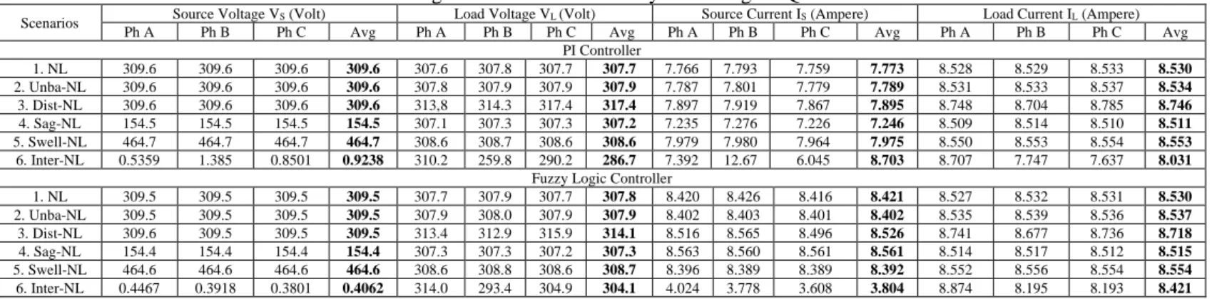
Therefore, in scenario 6, the UPQC-PV-BES combination with FLC is able to provide the load voltage and current performance better than the other two UPQC combinations. While in scenario 6, only the combination of UPQC-PV-BES with PI and FLC controller is able to produce a load voltage of 3720 W and 3700 W, respectively.
Moharana, "Performance Analysis of Unified Power Quality Conditioner in a Grid connected PV System", Proc of International Conference on Signal Processing, Communications, Power and Embedded Systems (SCOPES) 2016, Paralakhemundi, India, pp. Murali Sachithanandam, "Performance Study of Unified Power Quality Conditioner Using Artificial Intelligent Controller", International Review on Modeling Simulation (IREMOS), Volume 8, No. 1.
International Journal of Intelligent Engineering and Systems (IJIES)
Publication Option
Before Submission
Excellent Citation Award
Review Form
Loading Paper Title Optimization of Active Power Transfer Using UPQC-PV-BES System with Fuzzy Logic Controller. 1, "resources are available", "This device has been a function", "This model is used to improve PQ and reduce the burden", "Artificial neural network (ANN) based on SRF theory as a control to compensate PQ The problems of 3P3W system through UPQC for various balanced/unbalanced/distorted conditions in load and source have been", "UPQC applied to 3P4W system." “Both studies show”, “BES is also expected to be able to save the excess energy produced by PV and use it”, “because it has”, “power transfer into action”, etc…….You should point out the difference with other methods to further clarify the position of this work.
Jamet, “Vehicle Detection on Aerial Images”, International Journal of Intelligent Engineering and Systems, Vol.1, No.1, pp.
Paper ID Ijies2893
Paper Title Load Active Power Transfer Enhancement Using UPQC-PV-BES System With Fuzzy Logic Controller
Reviewer comment to the authors
BES is also expected to be able to save excess power generated by PV and "use" it as reserve power revised to BES is also expected to be able to save excess power generated by PV and "use" it as reserve power (page 3, column 1, section 2, Red writing). The PV-UPQC combination was also able to reduce harmonics due to non-linear loads and "is" able to keep total harmonic distortion (THD) revised to The PV-UPQC combination was also able to reduce harmonics due to non-linear loads and. Unbalanced load voltage "contains" harmonics and "pure unbalanced pure load voltage"...revised to Unbalanced load voltage containing harmonics and "pure unbalanced load voltage"...(Page 2, column 1, section 3, red font).
Both methods "were" able to improve PQ and "reduce" distortion in output power reviewed in Both methods "were" able to improve PQ and "reduce" distortion in output power (Page 2, Column 2, Paragraph 3, Red Font). This” research showed that FLC in UPQC-BES supplied by PV was able to significantly... Red Font). The effectiveness of the "proposed" model is validated with UPQC and UPQC-PV, respectively reviewed in
Where 𝐼𝑃𝑉,𝑛, 𝐼𝑆𝐶,𝑛, and 𝑉𝑂𝐶,𝑛 "are" the photovoltaic current, short circuit current, and open circuit voltage under standard conditions (𝑇𝑛 = 250𝐺 = 250𝐺) 𝑚2), revised to Where 𝐼𝑃𝐶,𝑛, and 𝑉𝑂𝐶,𝑛, respectively. ,𝑛 "is" the photovoltaic current, short circuit current and open circuit voltage under standard conditions (𝑇𝑛 = 250𝐶 and 𝐺𝐶 and 𝐺𝑊/ly. The common DC link voltage value depends on the instantaneous energy that can be generated by UPQC which "is" defined in Eq. .13 revised to The common DC link voltage value depends on the instantaneous energy that can be generated by UPQC which "is" defined in Eq.13 (Page 6, Column 2, Paragraph 1, Red Font). FLC is capable of oscillations to reduce and “produce”…….revised to FLC is able to reduce oscillations and “to produce”……….
The value of 𝑝̅𝑙𝑜𝑠𝑠 is one of the input variables to "get" the compensation current..revised to The value of 𝑝̅𝑙𝑜𝑠𝑠 is one of the input variables to "obtain" the compensation current, section 1,7,...(page 1 ,7,...) red font). During the fuzzification process, a number of input variables are calculated and converted "to" linguistic variables...revised to During the fuzzification process, a number of input variables are calculated and converted "to" linguistic variables...(Page 7, column 1) , para. 1, red font). Using the same procedure, the authors propose Eq. 14) for the effectiveness of UPQC-PV-BES "is formulated" below revised to "Using" the same procedure, the authors suggest Eq. 14) for the efficiency of UPQC-PV-BES "in the formula" below.
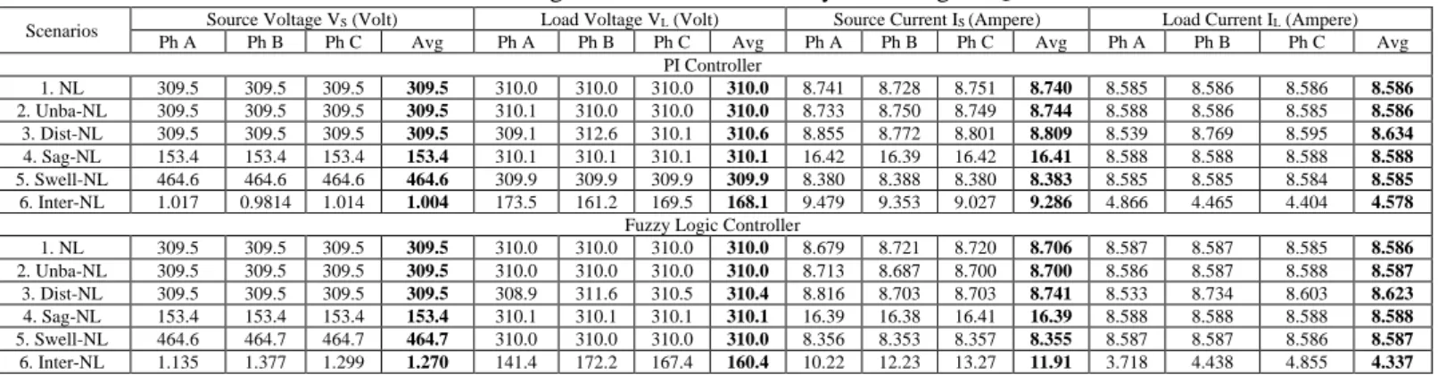
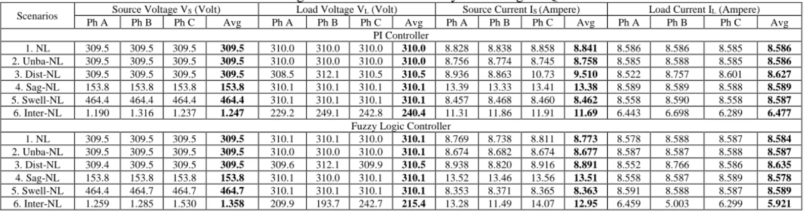
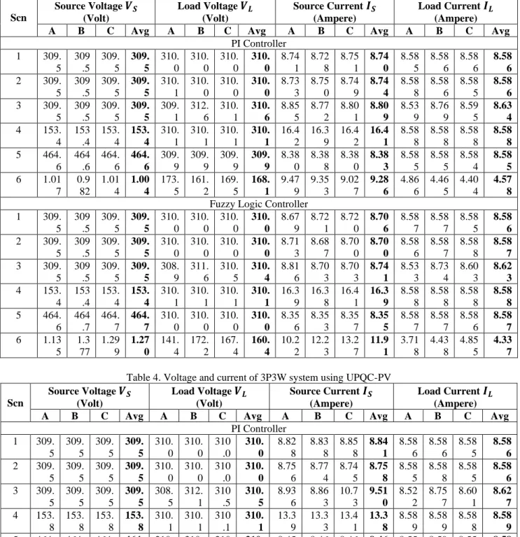
10 shows that in Scn 1 to 5 the 3P3W system "uses" three combinations of UPQC with PI and FLC control, "capable" of maintaining the load voltage above 300V, corrected in Fig. 10 shows that in Scn 1 to 5 the 3P3W system "using " of three UPQC combinations with PI and FLC control "is capable" of maintaining the load voltage above 300 V. 12.c.i, "in Scn 4, the UPQC-PV-BES combination shows the same performance on average" 𝑉𝐶 , 𝑉𝐿 and 𝐼𝐿 …….revised to Fig.
12.c.i “also shows that the UPQC-PV-BES combination in Scn 4 indicates almost the same performance on average” 𝑉𝐶, 𝑉𝐿 and 𝐼𝐿 ……….(Page 9, Column 2, Paragraph 2, Red font). Under this condition, the capacitor in UPQC DC link is "unable" to produce maximum power...revised to Under this condition, the capacitor in UPQC DC link. Under this condition, the UPQC-PV is "unable" to generate maximum... (Page 9, Column 2, Section 4, Red font).
However, in Scn 6, the combination of UPQC-PV-BES with FLC is able to produce load voltage, load current and load active power "higher compared to" UPQC-PV and UPQC revised to In Scn 6, but the combination of UPQC- PV-BES with FLC is capable of producing "higher" load voltage, load current and load active power. So, the UPQC-PV-BES model using FLC is able to compensate for "charge voltage".
In figures/equations, mathematical expressions must be Italic font.Unify the font style
I have revised mathematical expressions in Italic font for the figures/equations i.e
Future work of this paper i.e
The use of BES with different SoCs (0% to 99%) is proposed as a future work to determine the load active power transfer performance of the UPQC-PV-BES system in the under-charged state of the BES.
Thanks a lot for your constructive comments
We are appreciate for your kind guidance and valuable advices
Load Active Power Transfer Enhancement Using UPQC-PV-BES System With Fuzzy Logic Controller
Shunt Active Filter Control
The active shunt filter has the main function of mitigating PQ problems on the load side. The control method of the active shunt filter is that the absorbed current from the PCC bus is a balanced positive sequence current, including an unbalanced drop voltage on the PCC bus, an unbalanced or a non-linear load. The voltages and currents modeled in Cartesian coordinates can be converted to Cartesian coordinates 𝛼𝛽 in Eq. 9) shows calculation of real power (𝑝) and imaginary power (𝑞).
The total imaginary power (𝑞) and the fluctuating section of the actual power are selected as power and current references and applied using Eq. 10) for compensation of harmonics and reactive power [18]. Then the source current output reference is compared to the current source (𝑖𝑠𝑎, 𝑖𝑠𝑏, 𝑖𝑠𝑐) hysteresis current regulator to generate a trigger signal in the IGBT active filter circuit. In this paper, FLC is proposed as a DC voltage control algorithm on a shunt active filter and compared with a PI controller.
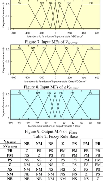
Fuzzy Logic Controller
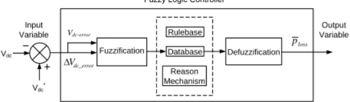
The source phase current (𝑖𝑠𝑎 ∗, 𝑖𝑠𝑎∗, 𝑖𝑠𝑎∗) is expressed in the abc axis obtained from the compensation current in 𝛼𝛽 coordinates and is shown in Eq. The value of 𝑝̅𝑙𝑜𝑠𝑠 is one of the input variables to obtain the compensation current (𝑖𝑐𝛼∗ , 𝑖𝑐𝛽∗ ) in equation (16). During the fuzzification process, a number of input variables are calculated and converted into linguistic variables based on a subset called the membership function.
In order to translate these variables, each input and output variable is designed using seven membership functions (MFs), i.e. The membership functions of input and output troughs are presented with triangular and trapezoidal membership functions. The value of 𝑝̅𝑙𝑜𝑠𝑠 then becomes the input variable for current hysteresis control to produce a trigger signal in the IGBT circuit of UPQC shunt active filter to reduce source current harmonics and load voltage harmonics.
UPQC-PV-BES Efficiency
International Journal of Intelligent Engineering and Systems, Vol.x, No.x, 20xx DOI: 10.22266/ijies2019.xxxx.xx The FLC method is implemented by determining the input. 𝑉𝑑𝑐− during the fuzzification process, the fuzzy rule base, as well as the krips value to determine 𝑝̅𝑙𝑜𝑠𝑠 in defuzzification. Once 𝑉𝑑𝑐− are obtained
The output MF is generated using inference block and basic rules of FLC as shown in Table 2.
Results and Discussion
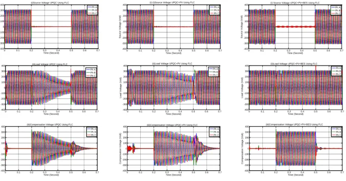
400 (c.ii) Load voltage UPQC-PV-BES Use FLC. a.iii) Compensation Voltage UPQC Using FLC Ph A Ph B Ph C. Time (Second) Source Current (Amperes) (a.iv) Source Current UPQC Using FLC. b.iii) Compensation voltage UPQC-PV Use FLC Ph A Ph B Ph C. (c) UPQC-PV-BES. b.v) Charge current UPQC-PV Using FLC Ph A Ph B Ph C. b.vi) DC switching voltage UPQC-PV Using FLC.
Performance of UPQC combinations using FLC in Scn 6: (a) UPQC; (b) UPQC-PV; (c) UPQC-PV-BES. b.iii) Compensation voltage UPQC-PV Using FLC Ph A Ph B Ph C. Active power transfer performance on three UPQC combinations using FLC in Scn 4. e.vi) BES Power UPQC-PV-BES Using FLC. Series active power (W) (c.ii) Series active power UPQC-PV-BES using FLC. a.iv) Load active power UPQC using FLC.
INVOICE
Copyright for this article is transferred to the Intelligent Networks and Systems Society (INASS) if and when the article is accepted for publication. The undersigned hereby transfers all rights in and to the paper, including without limitation all copyrights to the Intelligent Networks and Systems Society (INASS). The undersigned hereby represents and warrants that the paper is original and that he/she is the author of the paper, except for material clearly identified as to its original source, with permission notices from the copyright holders where necessary. It will not be submitted elsewhere for publication prior to acceptance/rejection by this conference/journal.
The corresponding author signs and assumes responsibility for the release of this material on behalf of all co-authors. This agreement must be signed by at least one of the authors who, if applicable, has obtained the consent of the co-author(s). After the submission of this agreement signed by the corresponding author, changes in authorship or in the order of authors listed will not be accepted.
Official Receipt
Acceptance Letter