YAYASAN BRATA BHAKTI DAERAH JAWA TIMUR
UI\IVE RSTTAS BHAYAI{GKA RA SURABAYA
LEMBAGA PENELITIAN DAN PENGABDIAN PNOA UNS?NNNTNT
(LPPM)
Kampus: Jl. A" Yani 114 surabaya Tetp. 031 - 8295602, g291055, Fax. 031 - g2g5601
STJRAT KETERANGAI\I
No-or ARA
Kepala Lembaga Penelitian dan
Pengabdiankepada Masyarakat (LPPM)
Universitas Bhayangkara Surabaya menerangkan bahwa:Nama
: Dr.Amirullah,
ST,MT.
NIP NIDN
:
19770520200501 1001 :4020057701Unit Kerja
: Universitas Bhayangkara Surabaya Benar telah melakukan kegiatan:1. Menulis jumal berjudul Power Quality
Enhancementof Integration
Photovoltaic Generatorto Grid under Variable Solar Irradiance Level using MPPT-Fuzzy(Amirullah
dan Agus Kiswantono) yang telah dipublikasikandi
lnternational Joumalof
Electrical andcomputer
Engineering (IJECE),vol.
6,No. 6,
December 2016,pp.2629^2642, ISSN:
2088-8708, Publisher: Instituteof
Advanced Engineering and Science (IAES).Terindeks
Scopus Q3.2.
Telah melakukan korespondensi melalui email dalam proses penerbitanjurnal
tersebut.Bukti
korespondensi email dan bulcti pendukung adalah benar sudah dilakukan oleh yang bersangkutan serta sudah dilampirkan bersama suratini.
Demikian surat keterangan
ini
dibuat untuk kepentingan kelengkapanpengusulan Guru Besar.;!.5uUuYu, 20 I arruan 2023 ,,Kepala LPPM
-p -\ \\
Drs. Heru
lrianto, M.Si.
NIP.9000028
''t
Lampiran 1
Bukti Korespondensi Email dengan Editor/Pengelola
Jurnal
[IJECE] Journal Registration
From: Tole Sutikno ([email protected]) To: [email protected]
Date: Saturday, 24 September 2016 at 07:35 am GMT+7
Amirullah '- Amirullah
You have now been registered as a user with International Journal of
Electrical and Computer Engineering (IJECE). We have included your username and password in this email, which are needed for all work with this journal through its website. At any point, you can ask to be removed from the journal's list of users by contacting me.
Username: amirullah
Password: medhurehsampang Thank you,
Tole Sutikno
---
How to submit your manuscript? (when the manuscript submission link is not activated)
To make a submission, you must have a user account and be enrolled as an Author. User accounts can either be created by the Journal Manager or you can register yourself (this journal policy allow you create user account by your self as a Reader, an Author and/or a Reviewer). All fields with an
asterisk beside them (Username; Password; Repeat Password; First Name; Last Name; Email) are mandatory. Your username and your email address must be unique; furthermore, while you can change your email address at a later date, you will be unable to change your username. If you want to register in another role within the same journal (for example, if you are already a Reader, but also want to become an Author) you can log in; go to Edit My Profile (under My Account on your User Home page); and check off the checkboxes next to any available roles, near the bottom of the page. Once you have an account, log in to the journal site and select the role of Author.
________________________________________________________________________
International Journal of Electrical and Computer Engineering http://iaesjournal.com/online/index.php/IJECE
[IJECE] Submission Acknowledgement
From: Tole Sutikno ([email protected]) To: [email protected]
Date: Saturday, 24 September 2016 at 10:02 am GMT+7
Dear Amirullah '- Amirullah:
Thank you for submitting the manuscript, "Power Quality Enhancement of Integration Photovoltaic Generator to Grid under Variable Solar Irradiance Level using MPPT-Fuzzy" to International Journal of Electrical and Computer Engineering (IJECE). With the online journal management system that we are using, you will be able to track its progress through the editorial process by logging in to the journal web site:
Manuscript URL:
http://iaesjournal.com/online/index.php/IJECE/author/submission/12748 Username: amirullah
If you have any questions, please contact us. Please refer to your paper ID whenever you communicate with our Editorial Office in the future. Your paper ID is latest number at Manuscript URL.
Thank you for considering this journal as a venue for your work.
Best Regards, Tole Sutikno
International Journal of Electrical and Computer Engineering (IJECE)
________________________________________________________________________
International Journal of Electrical and Computer Engineering http://iaesjournal.com/online/index.php/IJECE
Amirullah_PDF Avialable Online and Hardcopy Journal Issued
From: amir rullah ([email protected]) To: [email protected]
Date: Wednesday, 18 January 2017 at 05:43 pm GMT+7
Dear IJECE Journal Commitee, My paper for the title:
Power Quality Enhancement of Integration Photovoltaic Generator to Grid under Variable Solar Irradiance Level using MPPT-Fuzzy (Amirullah Amirullah, Agus Kiswantono)
has been accepted and published (avialable online) in Power Quality Enhancement of Integration Photovoltaic Generator to Grid under Variable Solar Irradiance Level using MPPT-Fuzzy | Amirullah | International Journal of Electrical and Computer Engineering (IJECE) Volume 6 Number 6 December 2016.
I would like to know:
1. When PDF of the paper will avialable online and could be downloaded by user?
In online version, the paper was only listed title of paper and name of authors 2. When hardcopy (book) of IJECE Journal will be issued?
If hardcopy have been issued, I will book it soon.
This is my question and I would be happy if you answer it.
Thanks a lot.
Regards,
Power Quality Enhancement of Integration Photovoltaic Generator to Grid und...
Power Quality Enhancement of Integration Photovoltaic Generator to Grid under Variable Solar Irradiance Level u...
Amirullah
Re: Send Paper ID 12748-26432-1-RV (Amirullah and Agus Kiswantono IJECE Journal 2016_Revised)
From: IJECE Journal ([email protected]) To: [email protected]
Date: Sunday, 5 February 2017 at 12:53 pm GMT+7
Just for 11 pages
On Wed, Nov 9, 2016 at 2:42 PM, amir rullah <[email protected]> wrote:
Dear Ms. Lyne Han (IJECE Commitee),
I need information again from you, have I to pay paper fee for 12 (before reduce) or 11 pages (after reduced)?
This information is very important before I pay paper fee today, in order making my paper online again in IJECE Vol. 6 No. 16 Dec 2016.
From previous email Dr. Tolle Sutikno email me that my paper accepted yesterday.
Please forgive me because I have just know from IJECE regulation that the paper payment as soon as possible.
This is my request and thanks a lot for your cooperation.
Amirullah
PhD Candidate in EE ITS Surabaya Lecturer Univ. Bhayangkara Surabaya +62-81-949649423
On Wednesday, 9 November 2016, 8:43, amir rullah <[email protected]> wrote:
Dear Ms. Lyne Han (IJECE Commitee),
I just have checked the list of paper Vol 6 No. 6 2016, why is my paper not in the list (missing)?
Yesterday I have checked paper include in the list after I got acceptance email.
How is about status of my paper accepted or rejected?
This information is very important for me before I will pay the paper fee (11 pages).
Amirullah
PhD Candidate ITS Surabaya Lecturer Ubhara Surabaya
On Wednesday, 9 November 2016, 8:20, amir rullah <[email protected]> wrote:
Dear Ms. Lyne Han (IJECE Commitee),
It is okay I means two weeks (not 2 times) depend on this information before (Please submit your payment receipt within 3 weeks ONLY to this email ([email protected]) Point 1.
For the point 2 please let me reduce number of paper page form 12 into 11 pages (attachment below). I have only made a final revision in placement of figure. I have not made significant revision to overall structure of this paper. As the fact, it is very difficult for me reduce number of pages from 12 to 8 pages.
Depend on the request for 11 pages the paper fee is (US 225 x Rp. 13.200) + (3 pages x 40 USD x Rp. 13.200) = Rp.
2.970.000 + 1.584.000 = Rp. 4.554.000 or USD 345 (Assume US 1 = Rp. 13.200.00) If the nominal paper payment is true, I will transfer it today.
For this I need information, is the payment to the bank account below in USD or Rupiah?
The payment should be made by bank transfer (T/T):
Bank Account name (please be exact)/Beneficiary: TOLE SUTIKNO Bank Name: Bank Mandiri, KCP Yogyakarta UGM
City: Yogyakarta Country : Indonesia
Bank Account # : 1370003247703 SWIFT Code: BMRIIDJAXXX
as alternative, You can by using PayPal to email: [email protected])
Power Quality Enhancement of Integration Photovoltaic Generator to Grid under Variable Solar Irradiance Level using MPPT-Fuzzy | Amirullah | International Journal of Electrical and Computer Engineering (IJECE)
Amirullah
PhD Candidate EE ITS Surabaya Lecturer Ubhara Surabaya
On Tuesday, 8 November 2016, 17:37, IJECE Journal <[email protected]> wrote:
Dear Sir,
1. It's too long time for 2 times, we will re-schedule for Feb'17 issue
2. We re-review your paper If you reduce your page-lengths from 12 into 8 pages
We will publish your paper for Dec'16 issue, if you pay the publication fee now, and only re-check your current paper version
Thank you Best Regards, Lyne Han
On Tue, Nov 8, 2016 at 4:15 PM, amir rullah <[email protected]> wrote:
Dear Dr. Tole Sutikno,
Thanks a lot for your information about acceptance of my paper in IJECE Vol. 6 No. 6. (Indexed Scopus Q3).
The title is Power Quality Enhancement of Integration Photovoltaic Generator to Grid under Variable Solar Irradiance Level using MPPT-Fuzzy (Amirullah Amirullah, Agus Kiswantono)
Power Quality Enhancement of Integration Photovoltaic Generator to Grid under Variable Solar Irradiance Level using MPPT-Fuzzy | Amirullah | International Journal of Electrical and Computer Engineering (IJECE)
Power Quality Enhancement of Integration Photovoltaic Generator to Grid und...
Power Quality Enhancement of Integration Photovoltaic Generator to Grid under Variable Solar Irradiance Level u...
Next I would revise the paper by reduce number page from 12 into 8 pages and pay accepted paper fee (USD 225) at least 2 weeks started from now.
Amirullah
PhD Candidate in EE ITS Surabaya Lecturer in Ubhara Surabaya
On Tuesday, 8 November 2016, 14:26, IJECE Journal <[email protected]> wrote:
Dear Dr. Amirullah,
It is my great pleasure to inform you that your paper is accepted and will be published on the International Journal of Electrical and Computer Engineering (IJECE), a Scopus indexed journal.
Congratulations!
This journal is an OPEN ACCES. Why publish open access? IAES open access authors benefit from:
Quality, established and reputable journal, reaching key audiences' with 5 million users per month, high citations, etc. Benefits of the OPEN ACCESS policy:
- Researchers as authors: immediate visibility for research output and thus increased visibility and usage of their results. Open Access may even lead to an increase of impact.
- Researchers looking for information: access to literature everywhere, not only from a campus but also from any site with wifi access.
- Funding agencies: increased return on investment (ROI), increased visibility.
- Universities & research institutes: greater visibility, clearer management information.
- Libraries: increased access for target audience, financially a more attractive model than the current subscription model.
- Teachers & students: unrestricted access to material, enriched education, allowing equality of learning in poor as well as in rich nations.
- Science: enhanced and accellerated research cycle.
- Citizens & society: access to knowledge / access to the results of publicly funded research.
- Enterprises: access to critical information.
- Publishers: transparent business model, ultimate online article distribution, ultimate visibility for articles.
So, Open access fee is paid by the authors, or on their behalf to support the cost of wide open access dissemination of research results, to pay deposit to CrossRef in order to each published articles has a Digital Object Identifier (DOI), to manage the various costs associated with handling and editing of the submitted manuscripts, and the Journal management and publication in general.
Each accepted paper will be charged: USD 225
This charge is for the first 8 pages, and if any published manuscript over 8 pages will incur extra charges USD40 per page
(http://www.iaesjournal.com/ online/index.php/IJECE/about/ submissions#authorFees)
The payment should be made by bank transfer (T/T):
Bank Account name (please be exact)/Beneficiary: TOLE SUTIKNO Bank Name: Bank Mandiri, KCP Yogyakarta UGM
City: Yogyakarta Country : Indonesia
Bank Account # : 1370003247703 SWIFT Code: BMRIIDJAXXX
as alternative, You can by using PayPal to email: [email protected]) Your paper will be scheduled after your payment reached us
Please submit your payment receipt within 3 weeks ONLY to this email ([email protected]) We really appreciate your total commitment to supporting this journal.
Thank you Best Regards, T. Sutikno Editor
http://www.iaesjournal.com/ online/index.php/IJECE
On Mon, Oct 24, 2016 at 7:36 AM, amir rullah <[email protected]> wrote:
Dear IJECE Commitee,
Here I send you revised paper (Paper ID 12748-26432-1-RV), the title is:
"Power Quality Enhancement of Integration Photovoltaic Generator to Grid under Variable Solar Irradiance Level
using MPPT-Fuzzy"
Amirullah, Agus Kiswantono, Study Program of Electrical Engineering, Faculty of Enginering, University of Bhayangkara Surabaya, Jl. Ahmad Yani 114 Surabaya 60231, East Java Province, Indonesia, Email:
[email protected], [email protected] This is my email and thanks a lot for your cooperation.
Amirullah
University of Bhayangkara Surabaya +62-81-949649423
Re: Amirullah_Request of Hardcopy IJECE Vol 6 No 6 Dec 2016
From: amir rullah ([email protected]) To: [email protected]
Date: Sunday, 5 March 2017 at 06:09 am GMT+7
Dear IJECE Journal Commitee, My paper including PDF for the title:
Power Quality Enhancement of Integration Photovoltaic Generator to Grid under Variable Solar Irradiance Level using MPPT-Fuzzy (Amirullah Amirullah, Agus Kiswantono)
has been accepted and published (avialable online) in Power Quality Enhancement of Integration Photovoltaic Generator to Grid under Variable Solar Irradiance Level using MPPT-Fuzzy | Amirullah | International Journal of Electrical and Computer Engineering (IJECE) Volume 6 Number 6 December 2016.
So I would order the hardcopy (book) IJECE Journal Volume 6 Number 6 December 2016.
How much is one hardcopy book for my edition (as Indonesian Author) and what is your account number?
This information is important for me to transfer hardcopy of my IJECE Journal Edition.
This is 3rd email sending you and I would be happy if you respond it.
Thank you very much.
Regards, Amirullah
On Saturday, 4 February 2017, 9:13, amir rullah <[email protected]> wrote:
Dear IJECE Journal Commitee, My paper including PDF for the title:
Power Quality Enhancement of Integration Photovoltaic Generator to Grid under Variable Solar Irradiance Level using MPPT-Fuzzy (Amirullah Amirullah, Agus Kiswantono)
has been accepted and published (avialable online) in Power Quality Enhancement of Integration
Photovoltaic Generator to Grid under Variable Solar Irradiance Level using MPPT-Fuzzy | Amirullah |
International Journal of Electrical and Computer Engineering (IJECE) Volume 6 Number 6 December
2016.
I would like to know when hardcopy (book) of IJECE Journal will be issued?
If hardcopy have been issued, I will book it soon.
This is my question and I would be happy if you answer it.
Thanks a lot.
Regards, Amirullah
On Wednesday, 18 January 2017, 17:43, amir rullah <[email protected]> wrote:
Dear IJECE Journal Commitee, My paper for the title:
Power Quality Enhancement of Integration Photovoltaic Generator to Grid under Variable Solar Irradiance Level using MPPT-Fuzzy (Amirullah Amirullah, Agus Kiswantono)
has been accepted and published (avialable online) in Power Quality Enhancement of Integration Photovoltaic Generator to Grid under Variable Solar Irradiance Level using MPPT-Fuzzy | Amirullah | International Journal of Electrical and Computer Engineering (IJECE) Volume 6 Number 6 December 2016.
Power Quality Enhancement of Integration Photovoltaic Generator to Grid und...
Power Quality Enhancement of Integration Photovoltaic Generator to Grid under Variable Solar Irradiance Level u...
I would like to know:
1. When PDF of the paper will avialable online and could be downloaded by user?
In online version, the paper was only listed title of paper and name of authors 2. When hardcopy (book) of IJECE Journal will be issued?
If hardcopy have been issued, I will book it soon.
This is my question and I would be happy if you answer it.
Thanks a lot.
Regards, Amirullah
Power Quality Enhancement of Integration Photovoltaic Generator to Grid und...
Power Quality Enhancement of Integration Photovoltaic Generator to Grid under Variable Solar Irradiance Level u...
Lampiran 2
Bukti Pendukung
Lampiran 2.1
Naskah Makalah Submitted
International Journal of Electrical and Computer Engineering (IJECE) Vol.x, No.x, September 201x, pp. xx~xx
ISSN: 2088-8708 31
Journal homepage: http://iaesjournal.com/online/index.php/IJECE
Power Quality Enhancement of Integration Photovoltaic Generator to Grid under Variable Solar Irradiance Level
using MPPT-Fuzzy
Amirullah1, Agus Kiswantono2
1,2Study Program of Electrical Engineering, University of Bhayangkara Surabaya, Indonesia
Article Info ABSTRACT
Article history:
Received Jun 12th, 201x Revised Aug 20th, 201x Accepted Aug 26th, 201x
The paper presents power quality enhancement on low voltage of three phase grid caused by PV generator integration under variabel solar irradiance level on constant temperature and load. MPPT Fuzzy helps to generate duty cycle to control DC/DC boost converter of PV generators. This model was expected to improve power quality due to unbalance voltage and current, low voltage and current harmonics, and low input power factor. There were eigth scenarios PV generator connected to three phase grid using MPPT Fuzzy and compared with MPPT P and O. The research results that application of two methods on different irradiance and PV generator integration level produces unbalanced voltage value stable at 0%. At the same conditions, the use of MPPT Fuzzy results unbalanced current was greater than MPPT P and O. On solar irradiance level fixed, the greater number of PV generator connected to three-phase grid, then value of average voltage and current harmonics (THD) will increases. At the level of solar radiation increases, average grid voltage and current THD also have increased. The average grid voltage and current THD was reduced after using MPPT Fuzzy. The application of MPPT Fuzzy was able to enhance profile of grid voltage and current THD due to integration of a number of PV generator to three phase grid corresponding with IEEE Standard 519-1992. MPPT Fuzzy was capable to improve input power factor better than MPPT P and O.
Keyword:
Photovoltaic Generator Power Quality
Harmonics Unbalance Power Factor MPPT P and O MPPT Fuzzy
Copyright © 201x Institute of Advanced Engineering and Science.
All rights reserved.
Corresponding Author:
First Author,
Study Program of Electrical Engineering
Faculty of Enginering, University of Bhayangkara Surabaya Jl. Ahmad Yani 114 Surabaya 60231, East Java Province, Indonesia Email: [email protected], [email protected] 1. INTRODUCTION
The output power of photovoltaic (PV) array is mainly affected by solar irradiance and temperature.
The output power of PV array is a function of terminal voltage and there is only one terminal voltage value where PV panels are used efficiently. The searching procedure of voltage is called maximum power point tracking (MPPT). Several algorithms have been developed to achieve MPPT technique. Theses are algorithms perturb and observe (P and O), incremental conductance, open circuit voltage, short circuit current, neural network and fuzzy logic controller. PV generator required a converter for generating DC into AC power and achieve MPPT. MPPT can be achieved in one or two stages. First stage, PV array is connected to grid through a DC/AC converter and its used to obtain MPPT and generated DC voltage once. Second stages, PV array connected to grid through DC/DC and DC/AC converters. In these condition, MPPT is obtained through a DC/DC converter control PV input voltage. While PV inverter change voltage from DC/AC and keep DC/DC converter output voltage remain constant. The research of MPPT on PV development using artificial intelligence control algorithm which are neural network and fuzzy logic controller have already done [1]. The advantage of using both methods is to increase limit of stability and efficiency. Neural network controller takes time for learning process, resulting in a slower system response. Fuzzy logic control method is more popular than the neural network because it have more accurate, high performance, and maximum efficiency. Many studies in the field related to PV panel operation errors, especially at low solar irradiance and high temperature degree [2].
The problem of PV generator connected to grid, beside to functioning to supply power to low voltage distribution network, is also reducing electric power quality for example unbalance current and voltage, current
ISSN: 2088-8708
IJECE Vol. x, No. x, September 201x : xx – xx 32
and voltage harmonics, as well as input power factor. It caused by tracking of MPPT which is influenced by non-linear characteristic panel depends upon varying environmental condition such as temperature and solar irradiance. Another cause is presence of converter as a medium to transform DC into AC voltage for (one stage converter) as well as DC into DC and DC into AC voltage (two stage converter). The using of multilevel inverter based shunt active power filter (SAPF) to improve power quality due to PV generator system connected to grid have been implemented [3]. The proposed method can efficiently be used for reactive power compensation and reducing source current total harmonic distortion (THD) up to 0.57%. The system is also capable of delivering active power with unity power factor to grid. The weakness of it were not discussing improvement harmonic voltage and PV generator connected to grid only one. Analysis of impact of PV generator connected to grid considering power quality (harmonic current) on the distribution already performed [4]. The results showed that injection of current harmonics generated by the customer side of the grid connected PV generation to still meet standart requirement. However the research did not discussed influence of PV integration on harmonics, fluctuations, and voltage flicker, as key parameter in power quality. Research on application of fuzzy logic as MPPT for controlling PV output voltage to achieve closed cycle control as smooth and fast in order to achieve maximum value power point of PV array have been already done [5]. PV systems both stand-alone and connected to grid has been modeled and simulated. The results showed that P-Q control scheme was able to provide closed control rapidly and PV system was able to generate a sinusoidal voltage with very small THD as 2.08%. The weakness of research is not disscussing current THD improvement due to integration of PV to grid and number of used PV only a single.
Analysis of power quality due to integration of multi-unit of PV generator connected to three phase grid under variable solar irradiation level have been implemented [6]. Research shows that grid voltage and current on point common coupling (PCC) bus before use double tuned passive filter on condition only connect one plant is still unstable. However, if PV generator connected to three-phase grid, amounted to more than one generator, then grid voltage and current becomes unstable. At level of solar irradiation remains, the greater number of PV generator connected to three-phase grid, then average THD of grid voltage and current increases.
At level of solar irradiation increases, average THD of grid voltage and current also have increased. Avarage THD of grid voltage and current reduced after double tuned passive filter installed. Nevertheless, MPPT control of PV generator still use P and O algorithm and did not use intelligent control. Power quality improvement of PV generator connected to three phase grid using Fuzzy Logic controller under changes in atmospheric conditions and solar radiation has been done [7]. In order to keep the system stable fuzzy logic controller is used to achieve it still has a unity power factor under all conditions. Fuzzy logic controller can improve overall system stability on a three-phase grid connected PV systems in some variation of parameters. Fuzzy logic control method is capable to reduce current THD compared to proportional integral (PI) and robust control.
The value of current harmonics using PI, robust, and fuzzy logic control successively reduced from 4.05%, 2.08%, up to 1.05% in order to achieve maximum power. However, number of PV generator connected to the grid is only single.
The purposes of research is to enhance power quality on low voltage of three phase grid caused by PV generator integration under variabel solar irradiance level on constant temperature and load using fuzzy logic controller. Model of PV generator system in singular to three-phase output voltage and connected three phase grid. DC/DC converter consists of a boost converter that functions to raise DC output voltage of PV generator. DC output voltage of boost converter circuit is then converted by the DC/AC inverter based pulse width modulation (PWM) algorthm into a three-phase AC voltage to three-phase grid. Then single PV generator is modeled and used to create multi PV generator connected to grid through a three-phase distribution transformer. Analysis of research includes effect of solar irradiance and integration of a number of PV generator to power quality on constant temperature and load. There are two scenarios PV generator connected to three-phase grid. They are using MPPT algorithm P and O and MPPT with Fuzzy Logic controller (MPPT Fuzzy). Each MPPT controller has four scenarios, then for a total has eight scenarios of PV generator integration level. Futhermore is to determine unbalance voltage and current, voltage and current THD, and power factor input on PCC bus of low-voltage three-phase grid. The final process is to validate the results of research refers ANSI/IEEE 241-1990 Standard (voltage and current unbalanced), IEEE 519-1992 Standard (voltage and current harmonics grid), and PLN Standard (input power factor).
The rest of this paper is organized as follow. Section 2 shows proposed model of single and three PV generator system connected to three-phase grid, MPPT P and O method, MPPT Fuzzy method, unbalance voltage and currect, power quality and harmonics, as well as power factor correction. Section 3 describes influence of solar irradiance and integration of PV generator to voltage and current unbalance, voltage and current THD of three phase grid, as well as input power factor on constant temperature and load using MPPT P and O and MPPT Fuzzy method. In this section, example cases studied are presented and the results are verified with those of Matlab/Simulink. Finally, the paper in concluded in Section 4.
IJECE ISSN: 2088-8708
Power Quality Enhancement of Integration Photovoltaic Generator to Grid……(Amirullah) 33 2. RESEARCH METHOD
2.1. Research Procedure
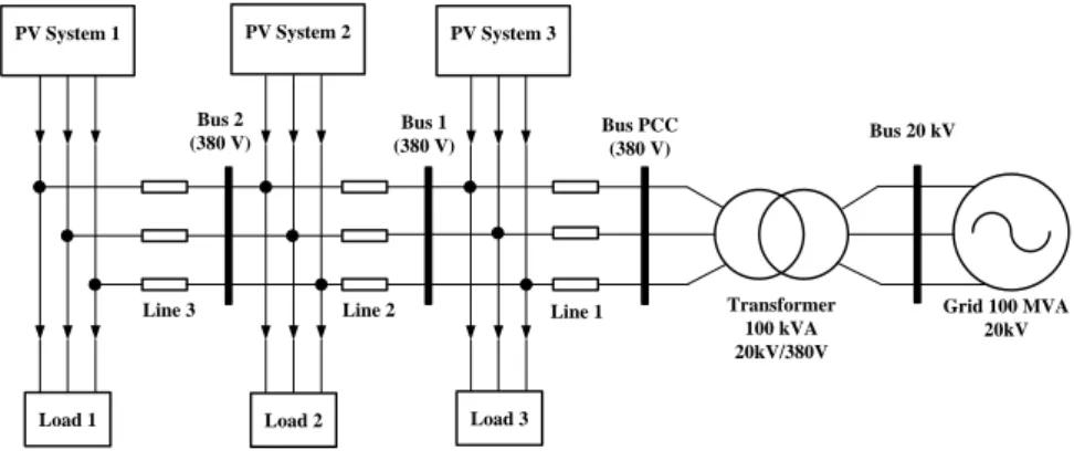
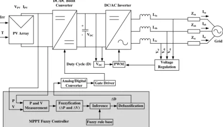
Figure 1 shows model PV generator connected to three phase grid using MPPT with Fuzzy Logic Controller (MPPT Fuzzy). Model of PV generator system in singular to three-phase output voltage and connected three-phase grid. DC/DC converter consists of a boost converter that functions to raise DC output voltage of PV generator. DC output voltage of boost converter circuit is then converted by the DC/AC inverter into a three-phase AC voltage to three-phase grid. Then single PV generator is modeled and used to create multi PV generator connected to grid through a three-phase distribution transformer (Figure 2). The study used three groups of PV generator model with an active power of 100 kW each. Beside that, PV generator is also connected on three groups of three phase load with active power 20 kW respectively.
The paper presents power quality enhancement on low voltage of three phase grid caused by PV generator integration under variabel solar irradiance level on constant temperature and load. Fuzzy logic controller helps to generate duty cycle (D) with a variable step to control DC/DC boost converter and subsequently result in rapid convergence calculations and more stable to determine MPPT of PV generator.
DC/DC converter generate a DC voltage that will be as input to DC/AC converter using PWM. This model is expected to reduce losses due to unbalance voltage and current, low voltage and current harmonics, and low input power factor. There are two scenarios PV generator connected to three-phase grid. They are using MPPT algorithm P and O and MPPT with Fuzzy Logic Controller (MPPT Fuzzy). Each MPPT control has four scenarios, then for a total has eight scenarios of PV generator integration level. Power quality aspects studied are unbalance voltage and current, voltage and current THD, and power factor input on PCC bus on eight scenarios using (a) MPPT P and O (b) MPPT Fuzzy as follow four conditions respectively (i) irradiance 400 W/m2, (ii) irradiance 600 W/m2, (iii) irradiance 800 W/m2, and (iv) irradiance 1000 W/m2 on condition 1, 2, and 3 of model PV generator connected to three phase grid. Futhermore is to determine unbalance voltage and current, voltage and current THD, and power factor input on each scenarios. The final process is to validate the results of research refers ANSI/IEEE 241-1990 Standard (voltage and current unbalanced), IEEE 519-1992 Standard (voltage and current harmonics grid), and PLN Standard (input power factor).
VPV
Vsa DC/DC Boost
Converter DC/AC Inverter
IPV
PV Array
P and V Measurement
PWM Voltage
Regulation Vsb Vsc Lia
Lib
Lic
Zsa
Zsb
Zsc
Grid Isa
Isb
Isc Irr
T
P V
Fuzzyfication
(∆P and ∆V) Inference Defuzzification
Fuzzy rule base
∆D Gate Driver Analog/Digital
Converter Duty Cycle (D) VDC
MPPT Fuzzy Controller VDC + -
Figure 1. Single PV generator connected three phase grid using MPPT Fuzzy
PV System 1
Load 1 Line 3
Load 2 Load 3
PV System 2 PV System 3
Line 2
Bus PCC
(380 V) Bus 20 kV
Transformer 100 kVA 20kV/380V Line 1
Bus 1 (380 V) Bus 2
(380 V)
Grid 100 MVA 20kV
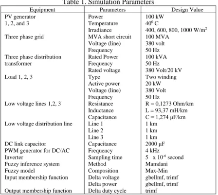
Figure 2. Proposed model of three PV generator system connected three phase grid Table 1 shows simulation parameters of three models PV generators connected to three phase grid.
ISSN: 2088-8708
IJECE Vol. x, No. x, September 201x : xx – xx 34
Table 1. Simulation Parameters
Equipment Parameters Design Value
PV generator 1, 2, and 3 Three phase grid
Three phase distribution transformer
Load 1, 2, 3
Low voltage lines 1,2, 3
Low voltage distribution line
DC link capacitor PWM generator for DC/AC Inverter
Fuzzy inference system Fuzzy model
Input membership function Output membership function
Power Temperature Irradiance MVA short circuit Voltage (line) Frequency Rated Power Frequency Rated voltage Type Active power Voltage (line) Frequency Resistance Inductance Capacitance Line 1 Line 2 Line 3 Capacitance Frequency Sampling time Method Composition Delta voltage Delta power Delta duty cycle
100 kW 400 C
400, 600, 800, 1000 W/m2 100 MVA
380 volt 50 Hz 100 kVA 50 Hz 380 Volt/20 kV Two winding 20 kW 380 Volt 50 Hz
R = 0,1273 Ohm/km L = 93,37 mH/km C = 1,274 μF/km 1 km
1 km 1 km 2000 μF 4 kHz 5 x 10⁻⁶ second Mamdani Max-Min gbellmf, trimf gbellmf, trimf trimf
2.2. MPPT P and O and MPPT Fuzzy
The initial research is to determine value of duty cycle (D) with a variable step to control DC/DC boost converter circuit with MPPT P and O algorithm. For PV converter, maximum power available is determined by PV cell characteristics, but this value often mismatches with the maximum power point (MPP) of the load.
By implementing MPPT in PV systems, MPP in PV cells can be maintained so that the number and size of PV panels can be reduced or energy yield can be optimized [8].
Due to moving of sun, which leads to change in irradiance, PV panels angle and variation of irradiance reaching the panels, energy generated from PV panels are absorbed does not constant over time. When this condition occurs, the VI characteristics changes and MPP will move. If the system was previously operating at MPP, there will most probably a power loss with the same operating point and new condition. To overcome these problems, MPPT has been developed. The system includes no moving parts (where the modules are moved to track the sun). MPPT search for the maximum power independent based on environmental conditions (following changes in solar radiation and temperature) and maintain the PV terminal voltage remains constant at maximum value. The most used method of MPPT is Perturb and Observe (P and O) that algorithm is shown in Figure 3 [9]. Figure 4 shows Matlab/Simulink model for control MPPT using P and O algorithm.
Start
Sense V(k), I(k) Calculate Power dP =P(k)-P(k-1)
dP>0
V(k)-V(k-1)>0 V(k)-V(k-1)>0
D = D + dD
D = D - dD D = D - dD D = D + dD
Yes No
No Yes
No Yes
Return
Figure 3. P and O Algorithm
IJECE ISSN: 2088-8708
Power Quality Enhancement of Integration Photovoltaic Generator to Grid……(Amirullah) 35
Figure 4. Matlab/Simulink model for MPPT using P and O algorithm
The next process is to perform same procedure for determining it using MPPT Fuzzy method showed in Figure 1. Fuzzy logic controller have been widely used in industrial process in the resent years due to their heuristic nature associated with simplicity, effectiveness and its multi-rule-based variable’s consideration for both linear and non-linear parameter variation of the system. Fuzzy system is composed of knowledge based rules system; the main part of Fuzzy Logic controller is knowledge of base consisting of the If-Then rules.
Fuzzy Logic is implemented to obtain the MPP operation voltage point faster with less overshoot and also it can minimize the voltage fluctuation after MPP has been recognized. It also is capable to enhance power quality problem for example unbalance current and voltage, current and voltage harmonics, as well as input power factor. The control objective is to track maximum power will lead consequently to effective operation of the PV panel. To design the FLC, variables which represent the dynamic performance of the system should be chosen as the input to the controller. The basic block diagram implemented in Fuzzy Logic Controller is shown in Figure 5 [9].
Database Reason Mechanism
Rulebase
Defuzzification Fuzzification
Pre- Processing
Post- Processing Fuzzy Logic Controller
Figure 5. Blok diagram of Fuzzy Logic controller
Due account MPPT Fuzzy method is in terms of intelligence and speed. Fuzzy MPPT method is done by determining input variables, namely fuzzy control output power (ΔP) and output voltage (ΔV) PV generator, seven linguistic variables fuzzy sets, fuzzy operating system block (fuzzyfication, fuzzy rule base, and defuzzyfication), Function ΔP and Δ V during fuzzyfication, a table fuzzy rule base, crisp values to determine duty cycle (D) in defuzzyfication phase with variable step to control DC /DC boost converter circuit. Figure 6 shows Matlab/Simulink model for control MPPT using Fuzzy Logic Controller.
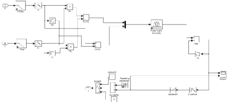
Figure 6. Matlab/Simulink model for MPPT using Fuzzy Logic Controller
ISSN: 2088-8708
IJECE Vol. x, No. x, September 201x : xx – xx 36
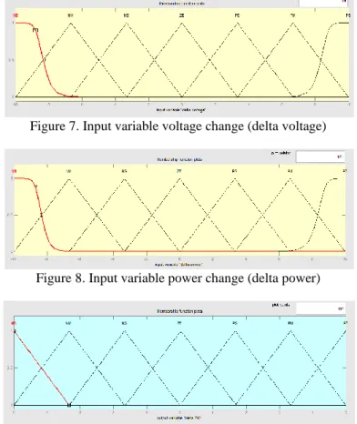
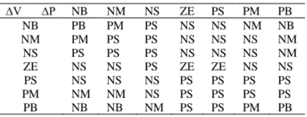
At fuzzyfication phase shown in Figure 5, a number of input variables is calculated and converted into a linguistic variable based on the subset called membership function (MF). To translate value of voltage change and power change in, input fuzzy "change of voltage" and "change of power" is designed to use seven fuzzy variable called PB (Positive Big), PM (Positive Medium), NS (Negative Small), PS (Positive Small) ZE (Zero), NM (Negative Medium), and Negative Big (NB). Voltage change (ΔV) and power changes (ΔP) is a proposed system input variables and output variable fuzzy logic control is duty cycle change value (ΔD). Membership function voltage changes, power changes, and duty cycle change, each shown in Figure 7 up to 9. Limit of input and output membership functions applied, determined by prior knowledge of parameter variations.
Figure 7. Input variable voltage change (delta voltage)
Figure 8. Input variable power change (delta power)
Figure 9. Output variable duty cycle change (delta D)
The fuzzy rule algorithm collects a number of fuzzy control rules in a specific order. This rule is used to control system to meet desired performance requirements, and they are designed from a knowledge of intelligent control systems. The fuzzy inference of fuzzy logic controller using a method that relates to a composition Mamdani Max-Min. Fuzzy inference system in fuzzy logic controller consists of three parts, namely rule base, database, and reasoning mechanism (Figure 5) . Rule base consists of a number of If-Then rule for proper operation of controller. The If side of rule is called antecedent and Then side is called consequence. These rules may be regarded as similar response made by human thought processes and controllers using linguistic input variables, obtained after fuzzyfication for the operation of these rules. The database consists of all user-defined membership function to be used in a number of these rules. Reasoning mechanism basically given processing rules based on specific rules and given conditions provides us the required result.
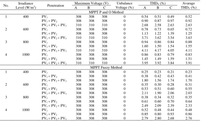
After determine ΔV and ΔP value, that value is then converted into linguistic variables and use them as input functions for fuzzy logic controller. The output value is ΔD is generated using block inference and fuzzy logic controller rules as shown in Table 2. Finally defuzzyfication block operates to change value of ΔD is raised from linguistic variables into numeric variables back. Numeric variables that become inputs signal for the IGBT switch of DC/DC boost converter to be able to determine MPPT value for each generation PV accurately at the same time also improve power quality as a result of integration of three PV generator to low voltage three phase grid.
Table 2. Fuzzy Rules
IJECE ISSN: 2088-8708
Power Quality Enhancement of Integration Photovoltaic Generator to Grid……(Amirullah) 37
∆V ∆P NB NM NS ZE PS PM PB
NB PB PM PS NS NS NM NB
NM PM PS PS NS NS NS NM
NS PS PS PS NS NS NS NM
ZE NS NS PS ZE ZE NS NS
PS NS NS NS PS PS PS PS
PM NM NM NS PS PS PS PS
PB NB NB NM PS PS PM PB
2.3. Harmonics
Power quality means the quality of voltage and current. Both are determined based on value or tolerance limit of equipment used. In general, current and voltage waveform is pure sinusoidal waveform. One problem that arises is wave of current and voltage is not sinusoidal or defects caused by emergence of harmonics generated by power system [10]. The term used to describe deviations harmonics sinusoidal wave associated with the current and voltage of different amplitude and frequency. Changes in current and voltage waveforms caused by harmonics will disrupt electrical distribution system and lower quality of power system.
In electric power system, harmonics can be described as a distorted periodic waveform at steady state are caused by interaction between shape of a sine wave at fundamental frequency system with another wave components which are integer multiples of the frequency of fundamental frequency sources. Figure 10 shows the signal waveform distortion due to harmonics.
Harmonic distortion explained through several key parameters to describe the effects of harmonics on power system components. The first parameter is Total Harmonic Distortion (THD). THD is ratio of rms value of harmonic components to rms value of fundamental component and is commonly expressed in percent (%).
This index is used to measure deviations periodic waveforms containing harmonics of a perfect sine wave [10].
On a perfect sine wave THD value is zero percent. Voltage THD value is expressed in Equation 1.
Figure 10. Distorted wave resulted by harmonics. Description a = wave at the fundamental frequency, b.1 = 3rd harmonic wave, b.2 = wave harmonics 5th, c = distorted wave.
% 100
1 2
2
=
=
U U THD
k
n n
V (1)
Description: Un = harmonic component; U1 = the fundamental component; K = maximum harmonic components
The second parameter is the Total Demand Distortion (TDD) or THDI is amount of current harmonic distortion and defined in following equation [10]:
%
2
100
2
=
= L k
n n
I
I
I
THD
(2)Where IL is the maximum load current (for 15 or 30 minutes) at the fundamental frequency at the PCC, calculated from the average current of the maximum load of 12 months earlier. THD value of the maximum allowable for each country is different depending on the standard used. THD standards most often used in electric power system is the IEEE Standard 519-1992 [11]. There are two criteria that are used in the analysis of harmonic distortion that voltage distortion limits and current distortion limits.
2.4. Voltage and Current Unbalance
ISSN: 2088-8708
IJECE Vol. x, No. x, September 201x : xx – xx 38
There are several standards that can be used to determine level of voltage unbalance in three-phase systems, e.g. IEC, NEMA, and IEEE. In this study, value of unbalance voltage use Equation 3 is based ANSI/IEEE 241-1990 Standard [12] as follows:
% 100 (%)
var
max min , ,
var −
=
age a
or c b a age a
V V
V V (3)
By using Equation 1, value of unbalance voltage expressed in percent (%) and is defined as follows;
Vavarage is the average value of maximum voltage on phase a, b, c, (volt), Va,b,c min is minimum voltage on phase a, b, c, (volt), Va,b,c max is maximum voltage on phase a, b, c (volt ). By using the same equation, then percentage of unbalance current can be calculated by replacing voltage magnitude into current magnitude.
2.5. Power Factor Correction
Power factor improvement or power factor correction (PFC) can be obtained based on value input harmonic distortion (THD) source current. Equation 4 shows input power factor as a function of source current THD [13]:
2
100 1 (%)
1
+
=
THDI
PF
(4)
PF is input power factor and THDi is current harmonics expressed in percent.
3. RESULTS AND ANALYSIS
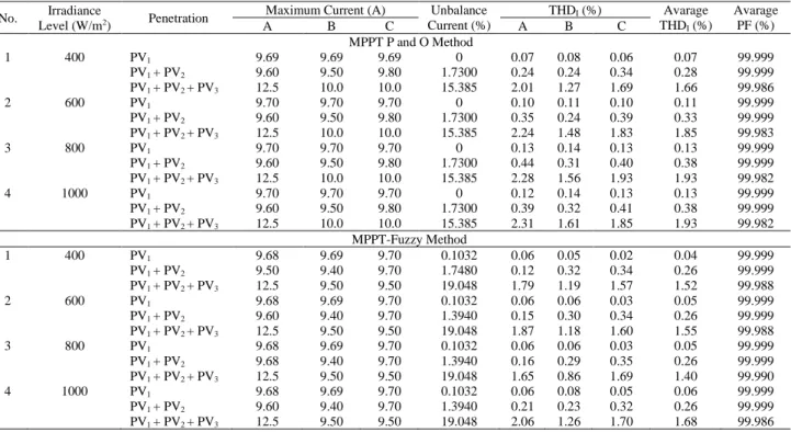
Analysis of results starts from determination maximum and minimum voltage grid on each phase, unbalance voltage using Equation 3, as well as voltage THD in three phase grid on PCC bus respectively, using MPPT P and O and MPPT Fuzzy. By using the same procedure subsequently obtained unbalance current value, current THD, and input power factor using Equation 4, based on grid current THD obtained previously. Table 3 show voltage unbalance and average voltage harmonic (THDV) grid in three model integration of PV generator and four different levels of radiation connected to three phase grid using MPPT P and O and MMPT Fuzzy. Table 4 shows unbalance current, average current harmonic (THDI), and input power factor on PCC bus at the same condition.
Table 3. Unbalance voltage and average voltage harmonic (THDV) grid No. Irradiance
Level (W/m2) Penetration Maximum Voltage (V) Unbalance Voltage (%)
THDV (%) Avarage THDV (%)
A B C A B C
MPPT P and O Method
1 400 PV1 308 308 308 0 0.54 0.51 0.49 0.52
PV1 + PV2 308 308 308 0 0.90 0.87 0.97 0.92
PV1 + PV2 + PV3 310 310 310 0 2.68 2.58 2.63 2.63
2 600 PV1 308 308 308 0 0.78 0.73 0.65 0.72
PV1 + PV2 308 308 308 0 1.13 1.22 1.39 1.25
PV1 + PV2 + PV3 310 310 310 0 3.71 3.62 3.54 3.63
3 800 PV1 308 308 308 0 0.94 0.86 0.84 0.88
PV1 + PV2 308 308 308 0 1.60 1.50 1.54 1.55
PV1 + PV2 + PV3 310 310 310 0 4.11 4.17 4.05 4.11
4 1000 PV1 308 308 308 0 0.86 0.83 0.79 0.83
PV1 + PV2 308 308 308 0 1.45 1.49 1.59 1.51
PV1 + PV2 + PV3 310 310 310 0 3.95 3.92 3.84 3.91 MPPT Fuzzy Method
1 400 PV1 308 308 308 0 0.25 0.23 0.21 0.23
PV1 + PV2 308 308 308 0 0.38 0.42 0.43 0.41
PV1 + PV2 + PV3 308 308 308 0 1.80 1.56 1.74 1.70
2 600 PV1 308 308 308 0 0.35 0.30 0.28 0.31
PV1 + PV2 308 308 308 0 0.53 0.51 0.60 0.55
PV1 + PV2 + PV3 308 308 308 0 2.11 1.90 2.06 2.03
3 800 PV1 308 308 308 0 0.38 0.34 0.32 0.35
PV1 + PV2 308 308 308 0 0.61 0.60 0.70 0.64
PV1 + PV2 + PV3 308 308 308 0 2.49 2.09 2.39 2.33
4 1000 PV1 308 308 308 0 0.52 0.48 0.44 0.48
PV1 + PV2 308 308 308 0 0.85 0.80 0.93 0.86
PV1 + PV2 + PV3 308 308 308 0 2.79 2.80 2.68 2.76 Table 4. Unbalance current, average current harmonic (THDI), and input power factor
IJECE ISSN: 2088-8708
Power Quality Enhancement of Integration Photovoltaic Generator to Grid……(Amirullah) 39
No. Irradiance
Level (W/m2) Penetration Maximum Current (A) Unbalance Current (%)
THDI (%) Avarage THDI (%)
Avarage PF (%)
A B C A B C
MPPT P and O Method
1 400 PV1 9.69 9.69 9.69 0 0.07 0.08 0.06 0.07 99.999
PV1 + PV2 9.60 9.50 9.80 1.7300 0.24 0.24 0.34 0.28 99.999
PV1 + PV2 + PV3 12.5 10.0 10.0 15.385 2.01 1.27 1.69 1.66 99.986
2 600 PV1 9.70 9.70 9.70 0 0.10 0.11 0.10 0.11 99.999
PV1 + PV2 9.60 9.50 9.80 1.7300 0.35 0.24 0.39 0.33 99.999
PV1 + PV2 + PV3 12.5 10.0 10.0 15.385 2.24 1.48 1.83 1.85 99.983
3 800 PV1 9.70 9.70 9.70 0 0.13 0.14 0.13 0.13 99.999
PV1 + PV2 9.60 9.50 9.80 1.7300 0.44 0.31 0.40 0.38 99.999
PV1 + PV2 + PV3 12.5 10.0 10.0 15.385 2.28 1.56 1.93 1.93 99.982
4 1000 PV1 9.70 9.70 9.70 0 0.12 0.14 0.13 0.13 99.999
PV1 + PV2 9.60 9.50 9.80 1.7300 0.39 0.32 0.41 0.38 99.999
PV1 + PV2 + PV3 12.5 10.0 10.0 15.385 2.31 1.61 1.85 1.93 99.982 MPPT-Fuzzy Method
1 400 PV1 9.68 9.69 9.70 0.1032 0.06 0.05 0.02 0.04 99.999
PV1 + PV2 9.50 9.40 9.70 1.7480 0.12 0.32 0.34 0.26 99.999
PV1 + PV2 + PV3 12.5 9.50 9.50 19.048 1.79 1.19 1.57 1.52 99.988
2 600 PV1 9.68 9.69 9.70 0.1032 0.06 0.06 0.03 0.05 99.999
PV1 + PV2 9.60 9.40 9.70 1.3940 0.15 0.30 0.34 0.26 99.999
PV1 + PV2 + PV3 12.5 9.50 9.50 19.048 1.87 1.18 1.60 1.55 99.988
3 800 PV1 9.68 9.69 9.70 0.1032 0.06 0.06 0.03 0.05 99.999
PV1 + PV2 9.68 9.40 9.70 1.3940 0.16 0.29 0.35 0.26 99.999
PV1 + PV2 + PV3 12.5 9.50 9.50 19.048 1.65 0.86 1.69 1.40 99.990
4 1000 PV1 9.68 9.69 9.70 0.1032 0.06 0.08 0.05 0.06 99.999
PV1 + PV2 9.60 9.40 9.70 1.3940 0.21 0.23 0.32 0.26 99.999
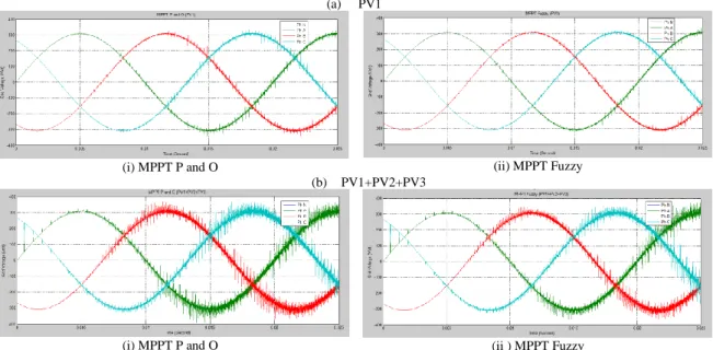
PV1 + PV2 + PV3 12.5 9.50 9.50 19.048 2.06 1.26 1.70 1.68 99.986 Figure 11 shows grid voltage on two models of PV generator integration connected to three phase grid under solar irradiance 1000 W/m2 on PCC bus using MPPT P and O, and MPPT Fuzzy method.
(a) PV1
(i) MPPT P and O (ii) MPPT Fuzzy
(b) PV1+PV2+PV3
(i) MPPT P and O (ii ) MPPT Fuzzy
Figure 11. Simulation results of grid voltage on two models of PV generator integration connected to three phase grid under solar irradiance 1000 W/m2 on PCC bus
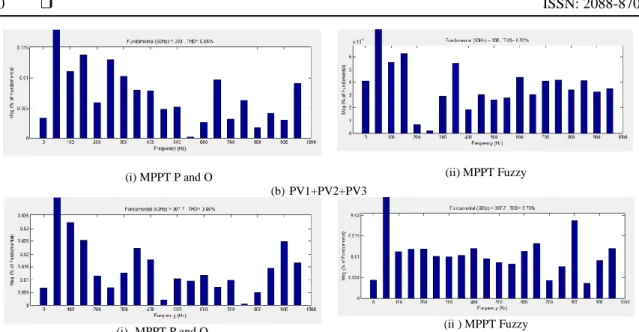
Figure 12 shows harmonics spectrum of grid voltage on two models of PV generator integration connected to three phase grid under solar irradiance 1000 W/m2 on PCC bus using MPPT P and O, and MPPT Fuzzy method.
(a) PV1
ISSN: 2088-8708
IJECE Vol. x, No. x, September 201x : xx – xx 40
(i) MPPT P and O (ii) MPPT Fuzzy
(b) PV1+PV2+PV3
(i) MPPT P and O (ii ) MPPT Fuzzy
Figure 12. Harmonics spectrum of grid voltage on two models of PV generator integration connected to three phase grid under solar irradiance 1000 W/m2 on PCC bus
Figure 13 shows curves of average voltage harmonics (THDV) on three models of PV generator integration and four levels of solar irradiance level connected three-phase grid on PCC bus using MPPT P and O, and MPPT Fuzzy method.
Figure 13. Average voltage harmonics (THDV) on three models of PV generator integration under solar irradiance level from 400 to 1000 W/m2
Table 3 shows that nominal grid voltage before using MPPT P and O method on the condition only connected to single generator (PV1) and two generators (PV1 + PV2) is still stable each as 308 volt. However, if PV generator connected to three phase grid equal as three (PV1 + PV2 + PV3), then grid voltage on bus PCC bus rises to 310 volt or 0.65%. MPPT P and O method results a nominal voltage unbalanced for all levels of radiation (400%, 600%, 800%, 1000%) and integration (PV1, PV2 + PV1 and PV2+PV1+PV3) as 0%. The application of MPPT Fuzzy method shows that grid voltage on each phase for all levels of radiation and integration generator level still stable at 308 volts and results voltage unbalance 0%. These results indicate that