We focus on three topics to explore the potential of the counterpropagating Brillouin laser gyroscope. By monitoring the beat shift of the counterpropagating lights, we can measure the rotation.
Commercial gyroscope
Blinking the light is equivalent to Michelson interferometry and creates a phase shift in the rotation. More precisely, the phase shift in rotation is independent of the refractive index of the medium.
Chip-based optical gyroscope
Independent counter-propagating Brillouin lasers therefore detect Sagnac rotation and become a chip-based ring laser gyroscope. A solid state ring laser gyro uses a III-V material as a gain medium to amplify counter-propagating lasers.
Summary of the Chapters
In the last part we showed the recent demonstration of the cascaded Brillouin laser gyroscope. To characterize the performance of whispering gallery mode, a number called quality factor (Q) is used.

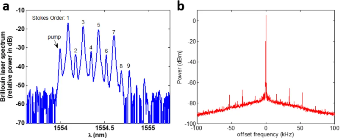
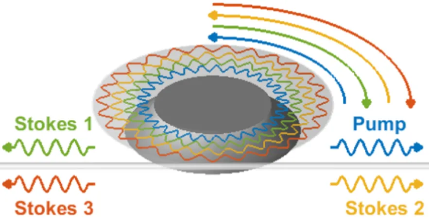
Brillouin laser generation
The pump continuously generates phonons and SBS photons in the resonator, and the SBS photons further accelerate the coherent conversion process. The interaction of the pump and the Stokes field generates a moving grating (phonon) in the medium.

Cascaded Brillouin laser
Since the lasers are in the same resonator, most of the common noise has been canceled. First, the lasers are kept in the same resonator, so most of the common noise has been canceled out through the impact process.
PHYSICS OF THE COUNTER-PUMPED BRILLOUIN LASER
Dissipative coupling, Kerr nonlinearity, and Sagnac effect
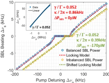
Green curve: The imbalance of SBL powers shifts the center of the closure zone from the Kerr nonlinearity. The high harmonics in the baseband come from the high harmonics of the Adler solution. The result shows that the high harmonic components in the baseband originate from the dissipative coupling disturbance near the coupling region.
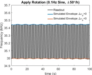
When the signal of the pump tuning frequency (high edge: ∆νp > 0, low edge: ∆νp < 0) is modulated by a dithering frequency (fd), the gyro readings have opposite responses to the external rotation. By calculating the frequency difference of the SBL beat signal (∆νsd=∆νs+−∆νs−), we double the throughput sensitivity.
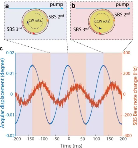
Backaction of the cascaded Brillouin laser
The resistance arises from the spread of the absorption (mode-pushing effect) proportional to the cascaded laser power. The beat frequency of the counterpropagating SBLs decreases as the cascaded laser power increases. The dual-SBL beat frequency follows the temperature dependence of the backaction under the cascaded power dither.
If we consider the temperature dependence of the laser mode near the threshold and γ/Γ 1, we have The polarity and amplitude of the indicator are determined by slow sawtooth dithering.

Conclusion
However, until recently, monolithic gyroscopes were limited in performance by the lack of waveguides and large optical resonators with sufficiently low optical loss. Analogues of fiber optic gyroscopes, passively resonant and ring laser gyroscopes in compact and often monolithic form have been reported. Unlike the previous chip-based Brillouin laser gyroscope that operated in cascade mode [12], the present device operates in a near-degenerate mode, similar to commercial ring laser gyroscopes.
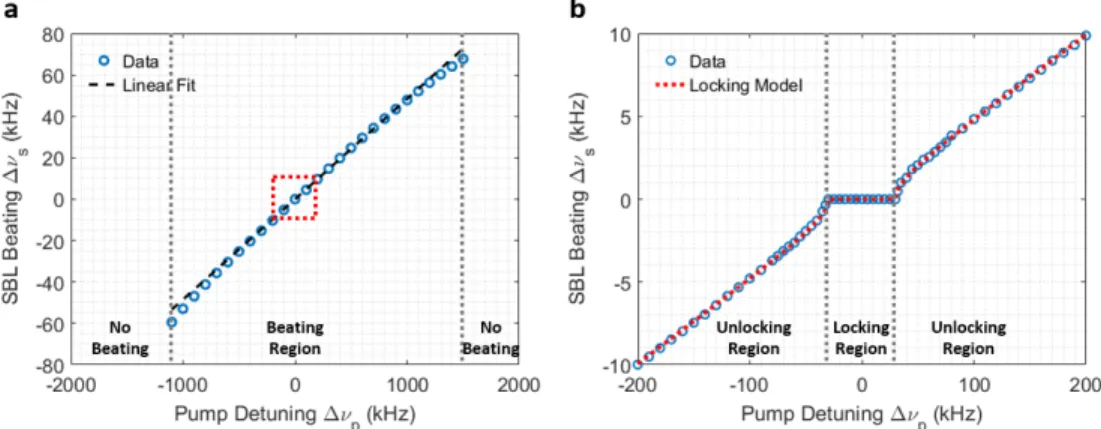
In this configuration, however, the device also becomes susceptible to a backscatter-induced locking effect, which is well known in commercial ring laser gyroscope systems. In the present work, we demonstrate a solid-state unlocking approach that relies on the underlying physics.
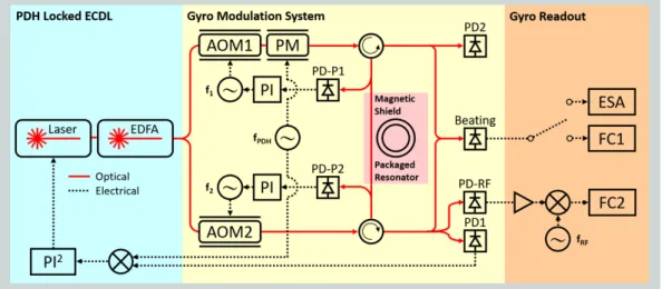
Offset-counter-pumping experiment
Beyond a critical level of Brillouin-induced scattering, the system is unlocked and gyroscope operation is possible. The gyroscope package is encased in a high-permeability magnetic shield to remove potential magneto-optical Faraday effect-induced non-reciprocity [ 70 , 71 ]. The entire gyromodulation system is enclosed in an environmental chamber to minimize the temperature shift.
In addition, D is the disk diameter, ng is the passive modal group refractive index, λ is the SBL wavelength, Ω is the rotational angular velocity, ∆PSBL is the output SBL power difference measured by OSA, his Planck's constant, and cis the speed of light.
Sinusoidal rotation measurement
The mode-pulling effect in the SBL process causes a small dispersion such that the Sagnac factor in an active resonator (red line and blue dots) is smaller than the Sagnac factor in a passive resonator (black dotted line). The relationship between the amplitude of the applied rotation and the shift of the peak frequency of the gyro reading is consistent with our model. Finally, we verified the existence of the mode drag correction factor in the Sagnac factor in Eq.
The mode-pulling correction factor can be viewed as the dispersion contribution of the SBS gain to the passive modal group refractive index. Both the Sagnac factors of the SBL gyro and the RMOG gyro retain a group refractive index term.

Schawlow-Townes linewidth, size effect, and drift reduction
The common drift from the external fluctuations is suppressed so that the bias drift of the gyro reading is low. The error bars show the standard deviations of the measured Allan deviations at the corresponding gate time. The value of the lowest point is called the bias drift, which is the limit of achievable sensitivity when averaging.
To further suppress the drift, we use the pump SBL beat frequency to track the drift of the modal SBL temperature and remove the correlated components from the dual-SBL beat frequency in post-processing. The correlation part of the pump-SBL beating is removed from the double-SBL beating by minimizing the standard deviation of the gyro readout signal (red trace in the inset of Figure 4.5b).
Earth’s rotation measurement
The measurement of the rotation of the Earth is a milestone for the development of the gyroscope, not only because the measurement proves the sensitivity of the gyroscope, but also because the motion of the system is suppressed to a certain level so that the gyro shows the potential for a field test and finding the north . . When the gyroscope orientation changes from North to South locally, the gyro axis and the Earth's axis have an angle equal to latitude (34.1◦ at Caltech). Furthermore, we change the sign of the detuning so that the polarity of the frequency shift changes according to our model.
We compare north-south data and east-west data to check the validity of the measurement. Dots/thick lines/dashed line: 1s average/30s average/full average of the gyro reading in each direction.

Introduction of exceptional point
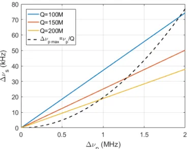
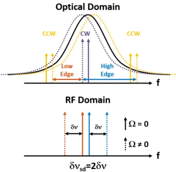
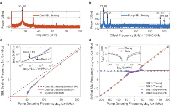
Dispersion from the Brillouin gain pulls the Stokes laser modes by different amounts toward the gain center due to the difference ∆ωp in the pump angular frequencies. The real part of the Brillouin gain factor leads to amplification of the Stokes mode, while the imaginary part is responsible for the mode-pulling effect. In the absence of backscattering (κ = 0), the CW and CCW SBL processes are independent because the Brillouin gain is intrinsically directional as a result of the phase-matching condition (Figure 5.1a).
The steady state of the lasing condition requires that the power loss rate γ is balanced by the Brillouin gain, leading to the pump power clamping state |Aj|2 = γ(1+ 4∆Ω2j/Γ2)/2g0 [48]. 5.2) By introducing κ, the laser system shows a transition between locking and unlocking the frequency as it changes the pump announcement frequency.

Enhancement near the exceptional point
The experimental data for the shifted SBL1 (SBL2) frequency are shown as blue (purple) circles. The inset shows the measured power ratio for CCW components of laser modes (blue circles) obtained by analysis of spectral components in panel bands is in reasonable agreement with the theoretical prediction (red solid curve). Furthermore, the ratio of the CCW components in the eigenmodes was measured from the intensity of the CCW pump beat with the SBL signals (see method of analysis) and is plotted as the inset of Figure 5.2d.
The frequency of the time-varying double SBL beat was recorded using a frequency counter, and the amplitude of the modulated frequency was extracted by applying a fast Fourier transform to the counter signal. The resulting Sagnac scale factor (i.e., the amplitude of the SBL difference frequency modulation divided by the amplitude of the applied rotation scale) is shown in Figure 5.3.
Methods: Detailed derivation related to EP physics Origin of the dissipative couplingOrigin of the dissipative coupling
These laser eigenmodes are valid in the uncoupled operation regime (..gt; ∆ωc) and are hybrid modes of the original CW and CCW modes. To make data plots within the inset of Figure 5.2d, the laser output in the CCW direction (combination of two laser Stokes waves) was monitored. The ratio of the forces in these beat frequency components is the ratio of the forces in the CCW Stokes wave components:. 5.17), which follows directly from Eq.
It is also interesting to note that in the closed regime (.. 1) numerical solution shows that eigenvector solutions with an equal mixing of CW and CCW waves occur when I1 = I2, but at distinctly different threshold power levels (i.e. the two conditions) have different loss rates). There are additional lines in these spectra that are thought to originate from nonlinear mixing in the Brillouin interaction (a third-order nonlinear interaction).
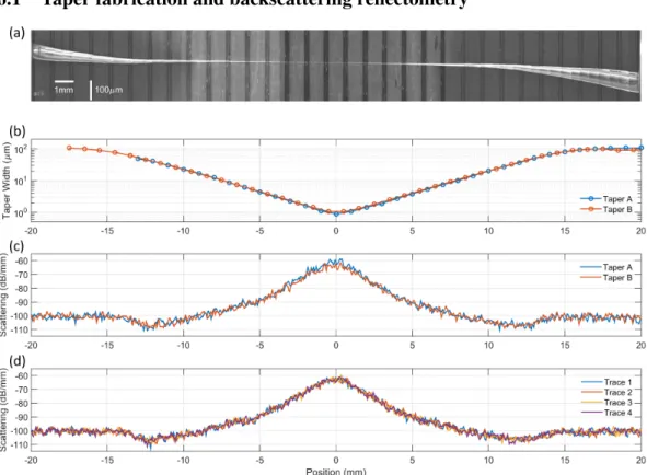
FIBER TAPER CHARACTERIZATION BY OPTICAL BACKSCATTERING REFLECTOMETRY
- Taper fabrication and backscattering reflectometry
- Scattering modeling and simulation
- Experiment results
- Derivation of Rayleigh scattering coefficient
- Conclusion
The narrow region of the taper has a length of only a few millimeters in the present work. First, the model provides a physical understanding of the behavior observed in the conical backscatter signal. A finite element solver is used to calculateσcore, σclad andη as a function of the cone width, w.
Using calculation procedure III, profiles of cone width versus cone position calculated for the four cones in Table 6.1 are presented in Figure 6.6b. It also includes a change of backscatter coupling to cone guidance mode due to variable cone width.
SUMMARY AND CONCLUSION
Sagnac phase shift in the fiber optical gyroscope
Next, let us consider a fiber optic gyroscope made of the dielectric medium of refractive index, n. At rest, the round trip time becomes nτr, since the speed of light in the medium isc/n. When the medium rotates, the speed of light is no longer the same due to Fresnel-Fizeau drag [116].
P , (A.19) where ∆P is the difference in round trip length between CW and CCW modes. A.13), this path length difference is calculated with. Furthermore, in a circular ring resonator, the mode optical path length is determined by.
OTHER SYSTEM DIAGRAMS
BIBLIOGRAPHY
Drift of an optical fiber gyroscope caused by the faraday effect: influence of the earth's magnetic field. Optical interface created by laser-cooled atoms trapped in the evanescent field around an optical nanofiber. Modified optical frequency domain reflectometry with high spatial resolution for components of integrated optical systems.

![Figure 1.3: Recent Chip-Based Gyroscopes. a, A microresonator Brillouin laser gyroscope made from a chip-based silica-on-silicon microresonator coupled with fiber taper waveguide.[12] b, A microresonator Brillouin laser gyroscope made from a chip-based sil](https://thumb-ap.123doks.com/thumbv2/123dok/10412395.0/20.918.285.638.105.756/gyroscopes-microresonator-brillouin-gyroscope-microresonator-waveguide-microresonator-brillouin.webp)