EVALUATION OF CHB MLI BASED SHUNT APF USING LOW-PASS FILTER AND SELF-TUNING FILTER. Amirullah Ubhara Surabaya
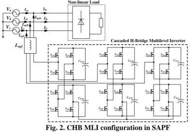
In addition, a noise-free sine wave form is one of the signs of good power quality. Meanwhile, poor quality of electricity in the power system is defined when the load connected to it fails or has a reduced life and efficiency of the electrical installation. As the number of levels increases, it will provide a step wave that approaches the desired waveform, so the harmonic distortion of the output wave will be reduced.
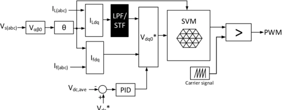
Control Algorithms
Harmonic extraction
- Low Pass Filter (LPF)
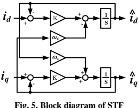
- Self Tuning Filter (STF)
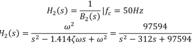
The change of the harmonic extraction from LPF to STF will significantly improve the performance of SAPF. The transfer function of generalized form of frequency response for nth order Butterworth LPF is shown in (1), where n is the order of the filter, ω is the passband frequency, ωc is the cutoff frequency and ε is the maximum passband gain. The cutoff frequency of the Butterworth LPF is 100π rad/s or equal to 50Hz as the fundamental supply frequency.
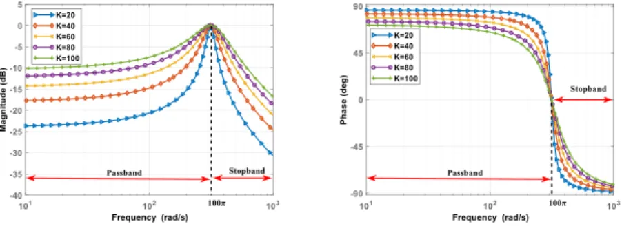
Based on (3) and (4), increasing the nth order value in Butterworth LPF will increase the complexity of the transfer function equation, even though the shape of the magnitude will approach the ideal property of LPF. Since the load current of d-q needs to be filtered, the equation of the synchronous frame can be written as mentioned in (4), where 𝐼̂𝑑𝑞(𝑡) and 𝐼𝑑𝑞(𝑡) represent the instantaneous signals of input and output of the STF filter. The constant K should be added in (5), to limit the magnitude as much as possible to reach the unity value at the cutoff frequency of the transfer function and at the same time the phase lag of the transfer function will be equal to zero at the time when the transfer function cutoff frequency .
- DC Link Capacitor
- Space Vector Pulse Width Modulation (SVPWM)
- Simulation Results and Analysis
- Conclusion
LPF-based harmonic extraction for inductive load at n=3: (i) three-phase line voltage, three-phase line current, three-phase load current and three-phase APF current, (ii) voltage and current at Phase A, ( iii) THD of line current at Phase A and. iv) THD of load current at Phase A. 11 shows the results obtained according to LPF-based harmonic extraction method for inductive load at filter order n of 3 and 9. STF-based harmonic extraction for inductive load at K=40: (i) three -phase line voltage, three-phase line current, three-phase load current and three-phase APF current, (ii) voltage and current at Phase A, (iii) THD of line current at Phase A and. iv) THD of load current at Phase A.
STF harmonic extraction for inductive load at K = 100: (i) three phase line voltage, three phase line current, three phase load current and three phase APF current, (ii) voltage and current at phase A, (iii) THD of line current at phase A and . iv) THD of load current in phase A. This article demonstrates the performance of LPF and STF based harmonic extraction algorithms in CHB MLI SAPF. Implementing a high degree of LPF-based harmonic extraction in hardware development is even more difficult.
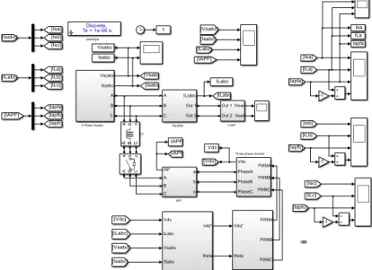
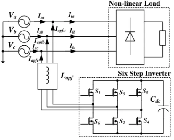
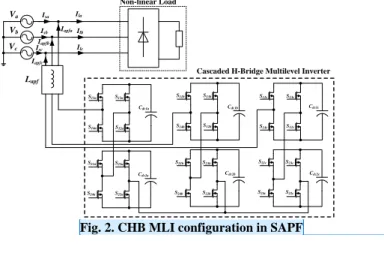
Multilevel Inverter in SAPF
Comment [WU3]: 3. After this paragraph in the introductory section, briefly explain the parts of the discussion in the paper, for example section 2 discussed .., section 3 discussed. The major disadvantage using LPF is high value of percentage error to be produced in phase and magnitude of the harmonic components, which contributes to smoothing to only high order harmonic components. The advantages of the STF, besides working well in steady and transient conditions, it does not require PLL, no unity gain and phase delay at the fundamental frequency component and easy to implement in digital or analog control system.
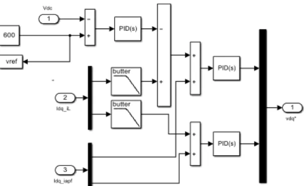
The constant value K or also known as the selectivity parameter will affect the performance of the STF as shown in fig. Based on the magnitude and phase of the bode plot, the cutoff frequency of the STF is 100π rad/s or equal to 50Hz as the fundamental delivery frequency. A DC-link capacitor, Cdc, is used as the storage element in the SAPF, operating continuously in a charged or discharged state of voltage from the power system to the load.
The stability of the SAPF depends on the ability of the voltage balancing algorithms to keep the DC voltage on the DC link capacitor closer to the capacitor voltage reference value. Therefore, using the energy balance concept, the energy charge of the capacitor is equal to the reactive and harmonics of the load current as stated in (18). By rearranging (18), the minimum size of the DC link capacitor can be written in (19), where ΔVdc is the maximum or minimum DC bus capacitor voltages, Vdc, ref is the DC bus capacitor voltage reference, Vs is the RMS value of the source voltage and ΔIL is the maximum RMS value of the reactive and harmonic load current.
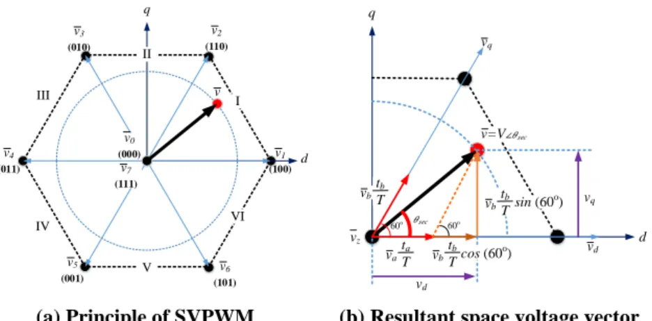
The fact that there is a degree of location freedom for the space vector in the switching cycle of SVPWM helps to improve the harmonic performance of MLI. 7(a) shows the principle of SVPWM, representing the three-phase output voltage of the inverter shown in the space vector diagram, which consists of six sectors and the resulting space voltage in sector I. Based on (24) and (25), and when the adjacent of the voltage vector is equal, the size is given by.
Hoon, et al., "A simple method for minimizing voltage deviations at the neutral point for a three-level based shunt active power filter", Int. Hoon, et al., “DC-Link Capacitor Voltage Control for Three-Phase, Three-Level, Inverter-Based Shunt Active Power Filter with Reverse Error Deviation Control,” Energies, vol. Kwak, “The analysis of an SCR-based ESD protection circuit with P-drift and N+ floating region”, Int.
REVIEW FORM
Title of paper: EVALUATION OF CHB MLI BASED SHUNT APF USING LOW PASS FILTER AND SELF- TUNING FILTER
- Technical aspects
- Comments to the authors (You may use another sheet of paper.)
- In the conclusion section of the abstract, state the quantitative analysis of your research results in the form of a decrease in the nominal THD value of the source current before and after using the
- Enlarge Fig 1 to the right and left ends of the paper page
- Move the title of sub-chapter 2 Multilevel Inverter in SAPF to sub-chapter 3.1 after sub-chapter 3
- Enlarge Fig 2 to the right and left ends of the paper page
- Change the title of sub-chapter 3 control algorithm to the proposed method
- Delete using the table for the equations and their numbers (Equations 1 to 36). Please directly copies the equations and numbers into the paper without the need to enter them into the table
- Enlarge and revise Figure 4a and Figure 4b from two columns to two rows of tables so that the readers can see the pictures and font writing clearly
- Enlarge and revise Figure 6a and Figure 6b from two columns to two rows of tables so that the readers can see the pictures and font writing clearly
- Enlarge and revise Figure 7a and Figure 7b from two columns to two rows of tables so that the readers can see the pictures and font writing clearly
- Revise Fig 10i, Fig 10ii, Fig 10iii, and Fig 10iv into four table rows (not two columns)
- Revise Fig 11i, Fig 11ii, Fig 11iii, and Fig 11iv into four table rows (not two columns)
- Revise Fig 12i, Fig 12ii, Fig 12iii, and Fig 12iv into four table rows (not two columns)
- Revise Fig 13i, Fig 13ii, Fig 13iii, and Fig 13iv into four table rows (not two columns)
- Revise Figure 14 into a 3-axis bar graph to explain the value of THD increase according to the author's proposed model and then, explain the analysis in as much detail as possible
- Describe in detail the weaknesses of your method and the future work needed to improve these weaknesses. Explain in a last single paragraph in the conclusion section
- Please state all nomenclature, all Greek symbols, all abbreviations and their respective meanings in table form between the conclusion section and references section
- Recommendation (Tick one)
- Comments to the editors (These comments will not be sent to the authors)
Change Figure 14 to a 3-axis bar graph to explain the THD increase value based on the author's proposed model, then explain the analysis in as much detail as possible. Please list all nomenclature, all Greek symbols, all abbreviations and their corresponding meanings in tabular form between the concluding section and the reference section.
EVALUATION OF CHB MLI-BASED SHUNT APF USING LOW PASS FILTER AND SELF-TUNING FILTER
MIMechE Editor-in-Chief, Journal of Engineering Science and Technology (JESTEC) http://jestec.taylors.edu.my. On behalf of the Editorial Board, I would like to thank you for your contribution in reviewing the following paper submitted to our journal. Professor and Dean, Faculty of Natural Sciences Engineering and Technology Director, Amity Institute of Food Technology.
Davoud Habibzadeh, Ph.D (Food Industries Science and Engineering - Food Technology) Department of Agriculture Food Science and Technology. Faculty of Nutrition Sciences and Food Industries Islamic Azad University of Tabriz, Tabriz IranE-mail: [email protected]. Department of Mechanical Engineering, Vasireddy Venkatadri Institute of Technology, Nambur, Gutur Dist., A.P. Electrical Engineering) Electrical Engineering Study Program Faculty of Engineering.
CiteScore counts the citations received in - articles, reviews, conference papers, book chapters, and data papers published in - and divides this by the number of publications published in .
Journal of Engineering Science and Technology
The journal publishes original contributions that contribute to the understanding of engineering science and the improvement of engineering technology and education. Dear how to email a journal to inquire about some publication requirements because there is no clear and specific email to the journal only through the executive editor prepared by researchers from several. I submitted an article for this journal about 6 months ago and still haven't received a decision. The problem is that the website of this magazine does not show any contact information other than the email of the executive editor, who has not responded to my emails since May 2020.
Unfortunately, we cannot help you with your inquiry, we suggest that you contact the journal's editors so that they can inform you in more detail. Unfortunately, we cannot help you with your inquiry. We suggest that you visit the journal's website or contact the journal's editors so that they can inform you in more detail. Unfortunately, we cannot help you with your query, we suggest that you contact the journal's editors so that they can inform you in more detail.
Dear Sukanto, thank you very much for your response, unfortunately we cannot help you with your request. Unfortunately we cannot assist you with your request. We recommend that you visit the journal's homepage (see submission/author guidelines) or contact the journal's editors for further information. I want to know if this magazine is considered an ISI magazine and what is the impact factor.
We suggest consulting the Journal Citation Report for other indicators (such as Impact Factor) with a Web of Science data source. The timeline for publication in this journal is approximately 2-3 months for final acceptance and may be 9 months for online publication. Unfortunately, we cannot help you with your request, we suggest that you visit the magazine's homepage or contact the magazine's editors, so that they can inform you more deeply.
This journal template has been used for the Kyoto APLSBE template 2019, which I have participated in, I am interested in the contents of this journal and wish to publish in this journal. I submitted a manuscript for publication in this journal, and two months later I received seven reviewers' comments. Dear Wadje, in the link below you will find the information corresponding to the author's instructions in this journal.