In a few months, by the beginning of 2015, the outline of the book series took its final shape in the form of a two-volume series of books on materials and technologies for aerospace aircraft - Aerospace Materials (Vol. 1) and Aerospace Material Technologies (Vol. 2). . Prasad is a Fellow of the Institute of Engineers (India) [FIE], Indian Institute of Metals [FIIM] and AP Akademi of Sciences [FAPAS].
Introduction
Abstract This chapter discusses in detail the special melting technologies adopted for the world-scale production of aerospace metals and alloys. Several case studies are included to illustrate the role of these fusion technologies in producing premium quality products for critical aerospace applications.
Vacuum Induction Melting (VIM)
- Functional Principle
- Melting Process
- Process Bene fi ts
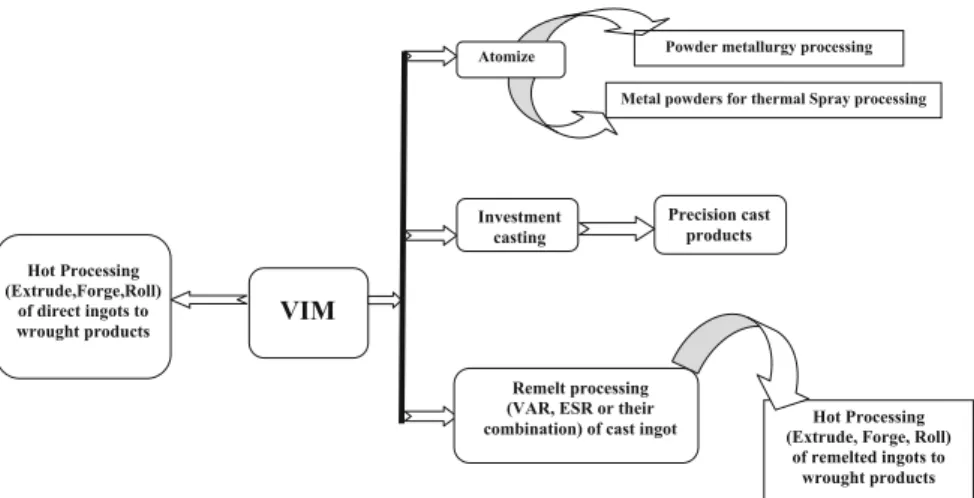
- Post-VIM Processing Technologies
- Manufacture of Nickel-Base Superalloy Investment Castings for Aerospace Gas Turbines — A Case Study
Degassing The reduced pressure during vacuum melting helps remove dissolved gases such as H2 and N2 by reducing their solubility in the liquid metal. Dissolved oxygen in liquid metal was estimated using oxygen sensors based on solid electrolyte (calcium-stabilized zirconium oxide). iii).
![Fig. 1.1 Schematic layout of VIM system [1]](https://thumb-ap.123doks.com/thumbv2/123dok/10240821.0/30.659.86.576.104.670/fig-schematic-layout-of-vim-system.webp)
Remelting Technologies
Remelting Processes
Protection of the metal droplets formed on the bottom of the consumable electrode from exposure to the atmosphere. Metal droplets appear on the bottom of the electrode and quickly form a pool of molten metal.
Re fi ning Characteristics
Equation 1.4 implies that desulfurization is not only favored by a high oxygen potential of the slag, aðOÞ, but also affected by low oxygen activity in the metal [wt.% O]. Vacuum Arc Remelting (VAR) Refinement phenomena in the VAR process are mainly controlled by exposure of the molten metal in vacuum to very high arc temperatures.
Solidi fi cation Phenomena
At the ingot's side surface, there is thus a net heat flow vector and grain growth direction parallel (0° angle) to the axis of the ingot. The ESR V-shaped pool profile extends the depth of the mushy zone and improves the interdendritic fluid flow.
![Fig. 1.7 Pool pro fi le and grain growth directions in remelted ingots [14]](https://thumb-ap.123doks.com/thumbv2/123dok/10240821.0/40.659.136.525.84.394/fig-pool-pro-grain-growth-directions-remelted-ingots.webp)
Solidi fi cation Defects: Superalloys
White Spots
Pieces of ingot crowns that fall into the metal pool and do not dissolve or remelt, thereby becoming embedded in the ingot. All three mechanisms mentioned above, individually or together, can be considered as possible sources of white spots.
Freckles
Ring Patterns: ‘ Tree Rings ’
A systematic investigation of tree rings shows that the change in the grain growth pattern is due to the change in the heat flow pattern at the solidification front [17]. This change in heat flux is due to the narrowed stabilization of the arc due to the higher arc power.
Case Study on Melt Processing of a Selected High-Temperature Material, Inconel 718
In turn, the higher arcing power is a result of the presence of shrink voids, porosity, and heavy contained inclusions, which draw higher current. The higher arc strength and narrowed arc stabilization result in a deepening of the molten metal pool and a reduction in the thermal gradient, causing the nucleation of new grains ahead of the columnar solidification front.
Titanium and Its Alloys
The survival of TiN particles depends on the melting rate and the length of their stay in the liquid pool. Larger, higher density sinking particles are of great concern, as they settle quickly to the bottom of the pool, where they may not dissolve because the alloy liquidus is below the melting temperature of TiN.
Secondary Metallurgical Processes
Defects can originate from foreign particles present in the raw material such as hard alpha TiN (a-I defects) or high-density W/WC particles and segregation-related solidification defects such as asa-II and b-flecks [23] . Thea-II and b-fleck defects are best controlled by using lower melting rates and maintaining a steeper temperature gradient at the solidification boundary to facilitate directional solidification [23].
Indian Scenario
This organization has been producing primary and secondary aerospace metals, alloys and components for the last 4-5 decades, mainly for Indian defense and space. Various new and augmented production facilities are rapidly coming up to meet the ever-growing needs of various Indian space and aerospace programs.
Summary
In: Lherbier LW, Bhat GK (ed) Proceedings of the "Vacuum Melting Conference on Melting and Machining of Special Metals". In: Lütjering G, Zwicker U, Bunk W (eds) Titanium Science and Technology: Proceedings of the fifth international conference on titanium, vol 1.
Introduction
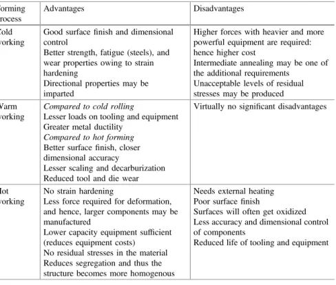
This chapter will also detail the processing of superalloys (nickel- and cobalt-based) and steels. One of the most important aspects of secondary processing is the workability of a metal or material, which includes malleability, rollability, extrudability and formability.
Fundamentals of Metal Forming
The three most important factors are reduction (strain), rate of reduction (strain rate) and temperature of the workpiece at any time. To get the best properties from an alloy, the starting material must be of the highest quality.
Bulk Deformation Processes
Forging
The three main categories of forging that are widely used are as follows: (i) open-die forging, (ii) closed-die forging (see Fig. 2.2 for the nature of the grain flow in a closed-die forged piece of metal) and (iii) press forging. Elimination of welding: Switching to closed die forging from multi-part welding leads to cost reduction in addition to property improvement.
Rolling
Extrusion
Secondary Processing for Speci fi c Aerospace Materials
Titanium Alloys
Superalloys
The forging methods for these alloys are similar in many ways to those for austenitic stainless steels. Cobalt-based alloys are characterized by low thermal conductivity and must be heated slowly to the soaking temperature to achieve uniform temperature.
Special Steels
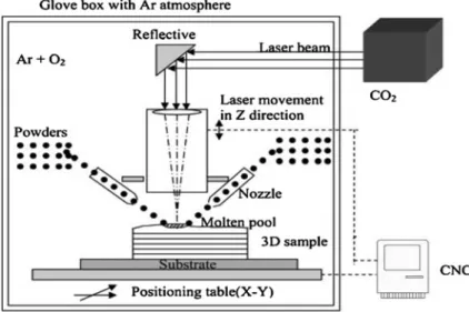
Recent Advances in Secondary Processing .1 Rapid Prototyping Using LENS
- Equal-Channel Angular Extrusion (ECAE)
- High-Pressure Torsion (HPT)
- Cryomilling
- Vacuum Plasma Spray (VPS) Forming
- Electrodeposition
The grain sizes obtained from ECAE are usually larger than 100-150 nm regardless of the metal or alloy. Due to the high pressure, high stresses can be applied without breaking the sample.
Summary
Grain sizes can be carefully controlled in the nc, ufc and mc ranges for sheets with thicknesses of 100–150lm. Finally, some applications of superplastic forming in the manufacture of aerospace components are presented.
Introduction
Superplastic molding leads to a reduction in component weight and manufacturing cost, and allows for new, monolithic aircraft component designs. However, cavitation present during superplastic forming of some alloys can lead to inferior properties and premature failure [1,3].
Phenomenology of Superplasticity
The deformation behavior of the material is divided into three areas: low (I), medium (II) and high (III) strain rate intervals, see Fig.3.1a. Grain size is inversely related to strain rate; and the relationship is often expressed by a power law.
![Fig. 3.1 The relationship between (a) stress and strain rate and (b) strain rate sensitivity index and strain rate for superplastic deformation [1]](https://thumb-ap.123doks.com/thumbv2/123dok/10240821.0/66.659.262.578.82.513/relationship-stress-strain-strain-sensitivity-strain-superplastic-deformation.webp)
A Review of Basic Research on Superplastic Flow .1 Metals and Alloys
- Intermetallics
- Ceramics
- Composites
- Bulk Metallic Glasses
- Effect of FSP on Superplastic Forming
46] analyze experimental data for the Mg–Zn–Zr system (alloys and composites ZK60 and ZK61) and propose a theory on the influence of reinforcement on superplastic flow in ceramics. Reduces the temperature range of superplastic forming by reducing the grain size of the starting material and results in uniform grain fineness.
Conventional/High Temperature Superplasticity
It is also known that when a hydrostatic pressure of 0.5ry is applied (ry is the yield stress), cavitation is completely suppressed. In superplastic sheet metal forming (biaxial), the hydrostatic pressure is applied on the opposite side of the forming pressure.
Low Temperature/High Strain-Rate Superplasticity
Forming Operations
- Bulge Forming
- Pressure Forming
- Sheet Thermoforming
- Blow (Extrusion) Moulding
- Deep Drawing
- Powder Metallurgy Processes
- Incremental Forming
- SPF/Diffusion Bonding of Titanium Alloys
- Superplastic Roll Forming
Pressurized gas applied to the top of the sheet pushes it to the bottom of the cover. Incremental forming processes are characterized by sequential local forming of the workpiece rather than forming in a single step.
![Fig. 3.3 Vacuum/pressure forming of a sheet by forcing it into a female die cavity: a four part cycle begins at the top left [83]](https://thumb-ap.123doks.com/thumbv2/123dok/10240821.0/74.659.139.522.495.848/vacuum-pressure-forming-sheet-forcing-female-cavity-begins.webp)
SPF Tooling
Techno-economic Considerations
Aerospace Applications
Aluminium Alloys
The parts are in the T6 condition (solution heat treated and artificially aged to peak strength). In the formed state, the alloy has suitable mechanical properties for internal fittings such as kick panels and lights.
![Figure 3.9 shows a 2195 Al – Li alloy SPF part produced at Boeing [100]. Other components superplastically formed from specially processed Al – Li 2090 and 2091 alloys at Superform are shown in Fig](https://thumb-ap.123doks.com/thumbv2/123dok/10240821.0/81.659.136.522.443.586/figure-produced-boeing-components-superplastically-specially-processed-superform.webp)
Titanium Alloys
An early demonstration of the benefits of the combined SPF/DB technology was a helicopter firewall manufactured by Rockwell International [105]. Figure 3.14 gives examples of SPF/DB manufactured components for the fuselage of the McDonnell Douglas F-15 tactical aircraft.
Additional Remarks
Conclusions
Morita K, Hiraga K, Sakka Y (2002) High strain rate superplasticity in Y2O3-stabilized tetragonal ZrO2 dispersed with 30 vol% MgAl2O4spinal. Morita K, Kim BN, Hiraga K, Sakka Y (2004) High strain rate superplasticity in 3 mol% Y2O3-stabilized tetragonal ZrO2 dispersed with 30 vol% MgAl2O4 spinel.
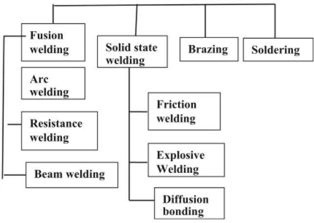
Developments in Welding Processes
For added strength and for welding dissimilar metals that are not fusion weldable, solid state welding processes such as friction welding and friction stir welding are used. To circumvent the problems in fusion welding and mechanical fastening, solid state welding processes such as friction welding and friction stir welding (FSW) have been introduced [3].
Welding of Aerospace Materials
- Aluminium Alloys
- Titanium Alloys
- Nickel-Base Alloys
- Steels
- Dissimilar Metals
- Metal Matrix Composites and Oxide Dispersion-Strengthened Alloys
- Intermetallics
Fusion welding processes used in the welding of aerospace components include gas arc welding (GTAW), plasma arc welding (PAW), gas arc welding (GMAW), butt butt welding, resistance welding and high energy density processes such as is an electron beam. (EB) welding and laser welding [1,2]. Brazing This is often used in the manufacture of compact aluminum heat exchangers (see Figure 4.3).
Innovative Welding Techniques
For example, innovative techniques such as pulse welding (PC) can be used instead of continuous current (CC) welding to further reduce heat input as well as introduce convective flow into the welding region. This achieves grain refinement in the weld region, as well as minimizes grain growth in the HAZ near the weld, and also addresses the segregation problem (Fig.4.11).
Ceramic – Metal Joining
In one such method, ceramic surfaces are metallized with a Mo-Mn coating to make them solderable with conventional filler metals such as Ag-Cu. Advances in this area have led to the development of active metal soldering, whereby active metals such as Ti are incorporated into the soldering alloy.
Advanced Welding Processes
The active metal reacts with the ceramic to facilitate brazing, thus avoiding the need to metallize the ceramic prior to brazing [46–50]. In the future, there is the possibility of using friction-based processes such as friction stir welding [54, 55], resulting in surface alloying to provide wear and corrosion resistance, and friction machining to refine grains in cast components and production of surface composites. 55].
Fixturing, Automation and Post-weld Heat Treatments
Summary
Madhusudhan Reddy G, Mohandas T, Sobhanachalam P (2003) Metallurgical and mechanical properties of AA 8090 Al-Li alloy friction stir welds. Madhusudhan Reddy G, Mohandas T, Bhanuprasad VV (2003) Friction welding studies of SiCp reinforced aluminum alloy AA2124 metal matrix composite.
Introduction
Abstract This chapter reviews the synthesis of nanomaterials by different nanofabrication processes (top-down and bottom-up), synthesis and properties of airgel and advanced electrodeposited coatings and their properties. Additionally, the potential applications of nanomaterials, aerogels and electrodeposited coatings in the aerospace industry are briefly explored.
Nanomanufacturing Processes
- Bottom-up Method
- Top-Down Method
- Graphene: A Special Case
- Challenges
As shown in Fig.5.3, mesoporous carbon materials with different geometries can be obtained by proper choice of silica template. Two of the best known methods are mechanical grinding and using RF induction plasmas to synthesize various metal oxides and metal nanoparticles from bulk particles.
Nanoporous Aerogels
Preparation of Aerogels
Properties of Aerogels
Electrodeposited Nanostructured Coatings
Pulsed electrodeposition (PRED) can be done by applying voltages or currents in the form of forward and reverse pulses at millisecond frequencies. Alternate forward and reverse pulses separated by zero voltage/current facilitate better control over the deposition process [22].
Potential Aerospace Applications: A Concise Survey
- Nanostructured Alloys
- Carbon Nanocomposites
- Aluminium-Based Propellant Materials
- Aerogel Thermal Insulation
- Electrodeposited Coatings
Most of the conventional electroplating alternatives have been based on nickel alloys [29], but these are also undesirable from an environmental point of view. Nanocrystalline coatings of Co-based (Co–P, Co–W, Co–Ni–Fe, Co–W–Fe) or Co-based alloys.
Indian Scenario
Research groups at the National Aerospace Laboratories (NAL) have developed Ni–Co and Ni–Co–ZrO2 coatings by electrodeposition and heat treatment. The tribological properties and corrosion resistance of the Ni–Co–ZrO2 coating were found to be better compared to hard chromium plating.
Summary and Conclusions
ARCI has worked on layered and graded nickel coatings and nanocoatings of Ni-W obtained from pulse electrodeposition. Shin JH, Lee JW, Park HS, Suh SJ (2014) Corrosion resistance of ultrasonic electrodeposited Ni-Co-Fe ternary alloy films according to current density.
Introduction
Summary This chapter provides a brief account of the various microscopic techniques for observing and interpreting microstructures of metals and alloys. Since it would be difficult to include the details of all the techniques, the reference list contains important resources for further details on all the techniques described in this chapter.
Microstructures: General Remarks
Optical Microscopy
From Eq.6.1 it follows that the resolving power is limited by the wavelength of the light: in fact, the maximum resolution (minimum) is typically approximately half the wavelength.
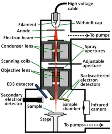
Scanning Electron Microscopy
SEM and Failure Analysis
The image magnifications that can be obtained in an SEM are typically about , although higher magnifications are possible with advanced. In particular, stereo pairs of fractographs that provide a full 3D effect can be very useful for detailed fractographic analyses.
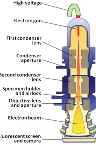
Transmission Electron Microscopy
- Transmitted and Diffracted Beam Imaging
- Bright-Field and Dark-Field Images
- Diffraction Patterns
- Characterization of Defects
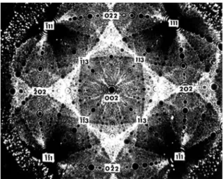
Analysis of a ring pattern gives the crystal structure and lattice parameter(s) of the responsible phase. A dot pattern makes it possible to determine the orientation of the crystal as well as the crystal structure and lattice parameter(s).
High-Temperature Microscopy
Determining the types of dislocations (whether edge, screw or mixed edge and screw) and the Burgers vector,b, is easily done using the extinction (invisibility) criterion g.b= 0, where g is the reciprocal lattice vector. TEM enables determination of misorientation between grains (both for low-angle and high-angle grain boundaries); error vector in stacking errors; the degree of coherence or incoherence between the two phases; sizes and volume fractions of precipitates; and many other features [15].
![Fig. 6.8 Sequence of micrographs taken during continuous heating of a melt-quenched Al – Rh alloy from room temperature up to about 555 °C in a TEM hot stage [16]: a supersaturated solid solution in the as-quenched condition, stable up to * 275 °C](https://thumb-ap.123doks.com/thumbv2/123dok/10240821.0/138.659.118.542.347.805/sequence-micrographs-continuous-quenched-temperature-supersaturated-solution-condition.webp)
Field Ion Microscopy
FIM Image Interpretation
Grain boundary structures can also be studied, and the presence of dislocations can be ascertained by observing spiral helices, for example the image in Fig.6.10. An additional complication was that the fine cubic phase coexisted with the tea-ferrite phase, which also has a cubic structure and similar lattice parameter.
Microstructural Studies in Aerospace Alloys
Concluding Remarks
In: Prasad NE, Gokhale AA, Wanhill RJH (eds) Aluminum-Lithium Alloys, Process Properties and Applications. Sanders TH Jr, Starke EA Jr (1982) Effect of slip distribution on the monotonic and cyclic ductility of Al-Li binary alloys.
Introduction
Texture De fi nition and Representations
For extrusions and drawn products, only one set of Miller indices [uvw] is required, where [uvw] represents the crystallographic direction of the unit cell parallel to the extrusion/drawing direction. The complete ODF consists of the sets of rotations pertaining to all the crystallites in the sample.
Methods of Measuring Texture
Orientation Distribution Functions Although polar figures provide a useful description of the texture found in a material and are usually sufficient for engineering purposes, the information is incomplete and at best semi-quantitative. This difficulty can be removed by using the crystal orientation distribution function (ODF), which describes the frequency of occurrence of particular orientations in a three-dimensional orientation space (Euler space).
Aluminium Alloys
Processing of Aerospace Aluminium Alloys
It is possible to determine the bulk texture of a material using EBSD if the scan is recorded from a large area (see for example Fig.7.2), but there are some limitations [3]. However, third generation Al-Li alloys required several processing and alloy chemistry modifications [6,8], including an intermediate recrystallization annealing, as shown in Fig.7.3b.
![Figure 7.3b is originally from Ref. [6]](https://thumb-ap.123doks.com/thumbv2/123dok/10240821.0/149.659.81.575.86.667/figure-b-is-originally-from-ref.webp)
Texture Effects on Aerospace Aluminium Alloy Properties
Fracture toughness The fracture toughness of aerospace aluminum alloys does not appear to be greatly affected by texture, but there are numerous microstructural features that have an influence [12] (see Fig.7.5). Yield strength – Fracture toughness Figure 7.5 is useful in showing that high-strength aluminum alloys are complex materials, from which it can be concluded that texture should not always be important in determining the properties of the final products.
Titanium Alloys
- Types of Commercial Titanium Alloys
- α + β Titanium Alloy Processing
- Processing Effects on Texture
- Texture Effects on Aerospace Titanium Alloy Properties
For Ti-6Al-4V, there are four deformation temperature regimes corresponding to the four columns of the pole diagram in Figure 7.9. Studies dating back to the 1960s have shown that strong textures affect the strength, modulus, fatigue and fracture toughness properties of titanium alloys.
![Fig. 7.7 Processing maps for fully equiaxed and mill annealed microstructures [14]](https://thumb-ap.123doks.com/thumbv2/123dok/10240821.0/155.659.85.575.90.630/fig-processing-maps-fully-equiaxed-annealed-microstructures.webp)
Nickel-Base Superalloys
However, the effects on fatigue strength are negligible and may be detrimental to fatigue crack growth. One last point is that since 1960, texture hardening of titanium alloys for spacecraft pressure vessels (reservoirs) has also been discussed [22].
Summary
In: Eswara Prasad N, Gokhale AA, Wanhill RJH (eds) Chapter 5 in 'Aluminium-lithium alloys: processing, properties and applications'. In: Eswara Prasad N, Gokhale AA, Wanhill RJH (eds) Chapter 13 in 'Aluminium-lithium alloys: processing, properties and applications'.
Introduction
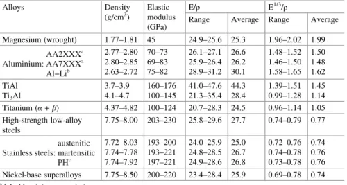
Abstract This chapter summarizes the importance of material density, elastic modulus, coefficient of thermal expansion, and thermal conductivity for the selection and use of several aerospace structural materials.
Aerospace Structural Components
Density and Stiffness
Aerospace Alloy Density and Stiffness Data
Most alloys have a specific stiffness in the range of 20-30 GPa/(g/cm3), with the exception of the titanium aluminides, especially TiAl, and some Al-Li alloys (see also Table 8.2). The reasons for these statements are given in the following section 8.3.2 on applications for the different alloy classes.
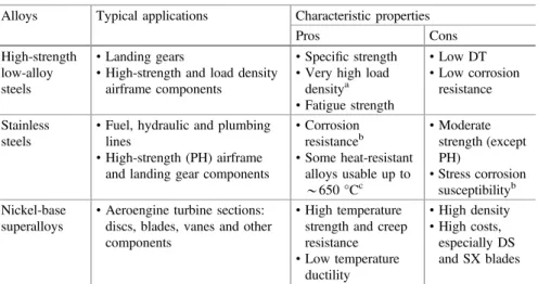
Alloy Classes and Applications
Al–Li alloys: High strength aluminum alloys are subject to increasing competition from carbon fiber reinforced plastic (CFRP) composites. More information on this complex topic is provided in Chapter 14 of Volume 1 of these Source Books.
Inadvisable Alloy Selection: A Case History
On the other hand, the aluminum alloys cannot compete in terms of specific kink resistance. DT is now the standard for both civil and military aircraft: see the first footnote to Table 8.1, Chap. 13 and 14 in Volume 1 and Chap.
Thermal Properties
Thermal Expansion Mismatch: Airframes
Thus, both boron epoxy and GLARE spots will lead to thermally induced residual tensile stresses in the aluminum substrate. After cooling to room temperature, the thermally induced residual stresses in the skin are therefore close to zero under a boron-epoxy patch and compressive under a GLARE patch [14].
![Table 8.4 Properties of materials involved in bonded repairs example [14]](https://thumb-ap.123doks.com/thumbv2/123dok/10240821.0/173.659.202.457.112.298/table-properties-materials-involved-bonded-repairs-example.webp)
Thermal Barrier Coatings (TBCs)
Table 8.5 lists some of the features and considerations as an albeit simplified illustration of the difficulties involved. Some properties of the different layers are indicated, as well as the large temperature drop due to the thermal barrier function of the topcoat.
![Fig. 8.9 Schematic of a TBC system deposited on a superalloy substrate [18]. The ceramic (porous oxide) topcoat is deposited by electron beam physical vapour deposition (EBPVD) or air plasma spraying (APS)](https://thumb-ap.123doks.com/thumbv2/123dok/10240821.0/175.659.85.574.87.352/schematic-deposited-superalloy-substrate-deposited-electron-physical-deposition.webp)
Concluding Remarks
Miller RA (2009) History of thermal barrier coatings for gas turbine engines: highlighting NASA's role from 1942 to 1990. This chapter discusses the determination of important ambient temperature mechanical and environmental properties of aerospace alloys at the basic level of sample and coupon testing.
Introduction
Abstract Standard data on mechanical and environmental properties at ambient temperature, including yield and tensile strengths, fatigue and fatigue crack growth, fracture toughness, corrosion and stress corrosion cracking, are essential—indeed, mandatory. The reader should consult Chapters 16-18 of this volume of the source books for information on structural alloy fatigue and residual strength testing at higher levels of the BB approach.
![Table 9.1 Example of a quali fi cation programme (Al – Li sheet/plate alloy) [2]](https://thumb-ap.123doks.com/thumbv2/123dok/10240821.0/179.659.80.583.105.689/table-example-quali-cation-programme-sheet-plate-alloy.webp)
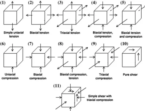
Mechanical Properties
- Tension Testing
- Compression Testing
- Stress – Strain Curve Moduli
- Shear and Bearing Strengths
- Hardness
Data includes yield strength, yield point, Young's modulus and compressive strength. The tangent modulus is the slope of the stress-strain curve at any given point and is equivalent to Young's modulus below the elastic limit.
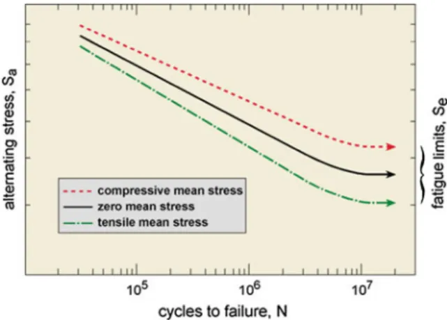
Fatigue
Some Important Remarks About the Commencement of Fatigue Cracking
Hardness data is very useful for quality control of structural alloys, especially steel, but also aluminum and other alloys. Despite these caveats, conventional fatigue testing is useful for material qualification programs and is still used for some hull lifting methods and analyses.
Fatigue Test Approaches
The basic result of the fatigue tests is an ε–2N (2 reversals = 1 cycle) diagram for fully reversed strain-controlled constant amplitude loading. The elastic strain equation is relevant to the high cycle fatigue regime, where the fatigue behavior is expected to be the same as in stress control.
Fatigue Crack Growth: Part I – Constant Amplitude Testing
Long/Large Cracks
This standard applies primarily to testing in ambient air, but also includes testing in aqueous environments. However, see Section 9.5.1 on Environmental FCG Testing of Aircraft Structural Alloys. Data presentation The growth rates of long/large fatigue cracks obtained from CA and CR loading are usually plotted against the LEFM stress intensity factor range, AK, at double-logarithmic (log-log) coordinates.
Short/Small Cracks
Cracks often behave in a mechanically minor manner when the ratio of crack size to crack tip plastic zone size is less than 4–20. Data presentation The CA short/small fatigue crack growth rates can also be plotted against ΔK on log-log coordinates.
![Table 9.2 Size criteria for small cracks [12]](https://thumb-ap.123doks.com/thumbv2/123dok/10240821.0/187.659.83.577.715.850/table-size-criteria-for-small-cracks.webp)
Fatigue Crack Growth: Part II – Variable Amplitude Testing
Introduction
Long/Large Cracks
Short/Small Cracks
Scanning electron microscope images can be difficult to interpret despite the application of tracer loads. These data indicate roughly exponential FCG, like many other VA short/small FCG data [8,30].
![Figure 9.7 is especially illustrative. These data indicate approximately expo- expo-nential FCG, as do many other VA short/small FCG data [8, 30]](https://thumb-ap.123doks.com/thumbv2/123dok/10240821.0/190.659.85.571.552.801/figure-especially-illustrative-indicate-approximately-nential-short-small.webp)
Fracture Toughness Testing .1 Introduction
Plane-Strain/Plane-Stress Fracture Toughness
ASTM E399-12e3: This standard is the most common and covers LEFM determination of plane strain fracture toughness using several types of specimens that have been previously fatigue cracked. ASTM E This standard is for plane strain fracture toughness using "short bar" and "short bar" chevron notched specimens.
K R Curves
However, although the fracture toughness is generally within ± 10 % of the values obtained from CT specimens [32], they are not considered valid Kc values. There is no standard for this regime, as the fracture resistance depends on the width of the sample and the starting point, as well as the thickness of the material.
Examples of K Ic and K R Curve Use
However, it is clear that crack growth resistance equal to or better than that of AA2524-T351 depends on the type of GLARE. A better crack growth resistance is definitely achievable with GLARE; and as discussed in Chapter 13 of Part 1 of these Sourcebooks, the excellent crack resistance of GLARE contributed to its use in upper fuselage panels of the Airbus A380.
Corrosion and Stress Corrosion Cracking (SCC) .1 Introduction
Corrosion
ASTM G This standard is an accelerated exfoliation corrosion test (EXCO test) for AA7XXX and conventional AA2XXX aluminum alloys. ASTM G This standard describes a general procedure for alternative corrosion testing by immersion in a neutral 3.5% NaCl solution.
Stress Corrosion Cracking (SCC)
Some SCC and Corrosion Issues
Summary
![Fig. 1.2 Schematic variation of furnace pressure at different stages of melting [1]](https://thumb-ap.123doks.com/thumbv2/123dok/10240821.0/30.659.84.574.89.390/fig-schematic-variation-furnace-pressure-different-stages-melting.webp)
![Fig. 1.3 Activity of C and O in an Fe – C – O system at different reduced pressures [2]](https://thumb-ap.123doks.com/thumbv2/123dok/10240821.0/31.659.255.577.588.888/fig-activity-c-o-fe-different-reduced-pressures.webp)
![Fig. 1.8 VAR process geometry showing locations of sources for potential fall-in of discrete particles [16]](https://thumb-ap.123doks.com/thumbv2/123dok/10240821.0/42.659.115.542.574.850/process-geometry-showing-locations-sources-potential-discrete-particles.webp)
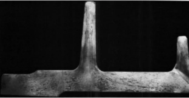
![Fig. 3.6 Fabrication of a titanium alloy multilayer cellular structure from a four-sheet package by means of SPF/DB [93]](https://thumb-ap.123doks.com/thumbv2/123dok/10240821.0/78.659.139.521.88.368/fabrication-titanium-alloy-multilayer-cellular-structure-sheet-package.webp)
