Network Indoor Station
Configuration Guide
Legal Information
©2022 Hangzhou Hikvision Digital Technology Co., Ltd. All rights reserved.
About this Manual
The Manual includes instructions for using and managing the Product. Pictures, charts, images and all other information hereinafter are for description and explanation only. The information
contained in the Manual is subject to change, without notice, due to firmware updates or other reasons. Please find the latest version of this Manual at the Hikvision website ( https://
www.hikvision.com/ ).
Please use this Manual with the guidance and assistance of professionals trained in supporting the Product.
Trademarks
and other Hikvision's trademarks and logos are the properties of Hikvision in various jurisdictions.
Other trademarks and logos mentioned are the properties of their respective owners.
Disclaimer
TO THE MAXIMUM EXTENT PERMITTED BY APPLICABLE LAW, THIS MANUAL AND THE PRODUCT DESCRIBED, WITH ITS HARDWARE, SOFTWARE AND FIRMWARE, ARE PROVIDED "AS IS" AND "WITH ALL FAULTS AND ERRORS". HIKVISION MAKES NO WARRANTIES, EXPRESS OR IMPLIED, INCLUDING WITHOUT LIMITATION, MERCHANTABILITY, SATISFACTORY QUALITY, OR FITNESS FOR A PARTICULAR PURPOSE. THE USE OF THE PRODUCT BY YOU IS AT YOUR OWN RISK. IN NO EVENT WILL HIKVISION BE LIABLE TO YOU FOR ANY SPECIAL, CONSEQUENTIAL, INCIDENTAL, OR INDIRECT DAMAGES, INCLUDING, AMONG OTHERS, DAMAGES FOR LOSS OF BUSINESS PROFITS, BUSINESS
INTERRUPTION, OR LOSS OF DATA, CORRUPTION OF SYSTEMS, OR LOSS OF DOCUMENTATION, WHETHER BASED ON BREACH OF CONTRACT, TORT (INCLUDING NEGLIGENCE), PRODUCT LIABILITY, OR OTHERWISE, IN CONNECTION WITH THE USE OF THE PRODUCT, EVEN IF HIKVISION HAS BEEN ADVISED OF THE POSSIBILITY OF SUCH DAMAGES OR LOSS.
YOU ACKNOWLEDGE THAT THE NATURE OF THE INTERNET PROVIDES FOR INHERENT SECURITY RISKS, AND HIKVISION SHALL NOT TAKE ANY RESPONSIBILITIES FOR ABNORMAL OPERATION, PRIVACY LEAKAGE OR OTHER DAMAGES RESULTING FROM CYBER-ATTACK, HACKER ATTACK, VIRUS INFECTION, OR OTHER INTERNET SECURITY RISKS; HOWEVER, HIKVISION WILL PROVIDE TIMELY TECHNICAL SUPPORT IF REQUIRED.
YOU AGREE TO USE THIS PRODUCT IN COMPLIANCE WITH ALL APPLICABLE LAWS, AND YOU ARE SOLELY RESPONSIBLE FOR ENSURING THAT YOUR USE CONFORMS TO THE APPLICABLE LAW.
ESPECIALLY, YOU ARE RESPONSIBLE, FOR USING THIS PRODUCT IN A MANNER THAT DOES NOT
DEVELOPMENT OR PRODUCTION OF WEAPONS OF MASS DESTRUCTION, THE DEVELOPMENT OR PRODUCTION OF CHEMICAL OR BIOLOGICAL WEAPONS, ANY ACTIVITIES IN THE CONTEXT RELATED TO ANY NUCLEAR EXPLOSIVE OR UNSAFE NUCLEAR FUEL-CYCLE, OR IN SUPPORT OF HUMAN RIGHTS ABUSES.
IN THE EVENT OF ANY CONFLICTS BETWEEN THIS MANUAL AND THE APPLICABLE LAW, THE LATTER PREVAILS.
Data Protection
During the use of device, personal data will be collected, stored and processed. To protect data, the development of Hikvision devices incorporates privacy by design principles. For example, for device with facial recognition features, biometrics data is stored in your device with encryption method; for fingerprint device, only fingerprint template will be saved, which is impossible to reconstruct a fingerprint image.
As data controller, you are advised to collect, store, process and transfer data in accordance with the applicable data protection laws and regulations, including without limitation, conducting security controls to safeguard personal data, such as, implementing reasonable administrative and physical security controls, conduct periodic reviews and assessments of the effectiveness of your security controls.
Network Indoor Station Configuration Guide
Symbol Conventions
The symbols that may be found in this document are defined as follows.
Symbol Description
Danger Indicates a hazardous situation which, if not avoided, will or could result in death or serious injury.
Caution Indicates a potentially hazardous situation which, if not avoided, could result in equipment damage, data loss, performance degradation, or unexpected results.
Note Provides additional information to emphasize or supplement important points of the main text.
Regulatory Information
FCC Information
Please take attention that changes or modification not expressly approved by the party responsible for compliance could void the user's authority to operate the equipment.
FCC compliance: This equipment has been tested and found to comply with the limits for a Class B digital device, pursuant to part 15 of the FCC Rules. These limits are designed to provide
reasonable protection against harmful interference in a residential installation. This equipment generates, uses and can radiate radio frequency energy and, if not installed and used in accordance with the instructions, may cause harmful interference to radio communications. However, there is no guarantee that interference will not occur in a particular installation. If this equipment does cause harmful interference to radio or television reception, which can be determined by turning the equipment off and on, the user is encouraged to try to correct the interference by one or more of the following measures:
—Reorient or relocate the receiving antenna.
—Increase the separation between the equipment and receiver.
—Connect the equipment into an outlet on a circuit different from that to which the receiver is connected.
—Consult the dealer or an experienced radio/TV technician for help
This equipment should be installed and operated with a minimum distance 20cm between the radiator and your body.
FCC Conditions
This device complies with part 15 of the FCC Rules. Operation is subject to the following two conditions:
1. This device may not cause harmful interference.
2. This device must accept any interference received, including interference that may cause undesired operation.
EU Conformity Statement
This product and - if applicable - the supplied accessories too are marked with "CE"
and comply therefore with the applicable harmonized European standards listed
Network Indoor Station Configuration Guide
under the EMC Directive 2014/30/EU, RE Directive 2014/53/EU,the RoHS Directive 2011/65/EU
2012/19/EU (WEEE directive): Products marked with this symbol cannot be disposed of as unsorted municipal waste in the European Union. For proper recycling, return this product to your local supplier upon the purchase of equivalent new equipment, or dispose of it at designated collection points. For more information see:
www.recyclethis.info
2006/66/EC (battery directive): This product contains a battery that cannot be disposed of as unsorted municipal waste in the European Union. See the product documentation for specific battery information. The battery is marked with this symbol, which may include lettering to indicate cadmium (Cd), lead (Pb), or mercury (Hg). For proper recycling, return the battery to your supplier or to a designated collection point. For more information see:www.recyclethis.info
Industry Canada ICES-003 Compliance
This device meets the CAN ICES-3 (B)/NMB-3(B) standards requirements.
This device complies with Industry Canada licence-exempt RSS standard(s). Operation is subject to the following two conditions:
1. this device may not cause interference, and
2. this device must accept any interference, including interference that may cause undesired operation of the device.
Le présent appareil est conforme aux CNR d'Industrie Canada applicables aux appareils radioexempts de licence. L'exploitation est autorisée aux deux conditions suivantes : 1. l'appareil ne doit pas produire de brouillage, et
2. l'utilisateur de l'appareil doit accepter tout brouillage radioélectrique subi, même si le brouillage est susceptible d'en compromettre le fonctionnement.
Under Industry Canada regulations, this radio transmitter may only operate using an antenna of a type and maximum (or lesser) gain approved for the transmitter by Industry Canada. To reduce potential radio interference to other users, the antenna type and its gain should be so chosen that the equivalent isotropically radiated power (e.i.r.p.) is not more than that necessary for successful communication.
Conformément à la réglementation d'Industrie Canada, le présent émetteur radio peut fonctionner avec une antenne d'un type et d'un gain maximal (ou inférieur) approuvé pour l'émetteur par Industrie Canada. Dans le but de réduire les risques de brouillage radioélectrique à l'intention des autres utilisateurs, il faut choisir le type d'antenne et son gain de sorte que la puissance isotrope
Cet équipement doit être installé et utilisé à une distance minimale de 20 cm entre le radiateur et votre corps.
Power Source Detail
The power source should be qualified and meet limited power source or PS2 requirements according to IEC 60950-1 or IEC 62368-1 standard.
Network Indoor Station Configuration Guide
Contents
Chapter 1 About this Manual ... 1
Chapter 2 Activation ... 2
2.1 Activate via iVMS-4200 Client Software ... 2
Chapter 3 Local Operation ... 3
3.1 Quick Operation (For DS-KH6320EY-WTE2) ... 3
3.2 Quick Operation (For Normal Device) ... 8
3.3 Basic Settings ... 15
3.3.1 Set Indoor Station Network Parameters ... 16
3.3.2 Set Linked Device IP ... 17
3.3.3 Set Wi-Fi ... 18
3.3.4 Set Indoor Station No. ... 19
3.3.5 SIP Settings ... 21
3.3.6 Add Camera ... 22
3.3.7 Zone and Alarm Settings ... 23
3.4 Password Settings ... 25
3.4.1 Change Admin Password ... 25
3.4.2 Security Settings ... 26
3.4.3 Modify Arm/Disarm Password ... 26
3.4.4 Modify Unlock/Duress Code ... 28
3.5 Synchronize Time ... 29
3.6 Sound Settings ... 29
3.6.1 Call Settings ... 30
3.6.2 Volume Settings ... 32
3.7 Via the mobile client ... 32
3.7.1 Link to the Mobile Client ... 32
3.8 System Settings ... 35
3.9 Output Settings ... 39
3.10 Device Information ... 40
Chapter 4 Remote Operation via the Client Software ... 41
4.1 Device Management ... 41
4.1.1 Add Video Intercom Devices ... 41
4.1.2 Modify Network Information ... 43
4.2 System Configuration ... 44
4.3 Remote Configuration ... 44
4.3.1 System ... 44
4.3.2 Video Intercom ... 50
4.3.3 Network ... 60
4.4 Person Management ... 64
4.4.1 Organization Management ... 65
4.4.2 Person Management ... 66
Appendix A. Relevant Instructions for External Power Supply and Wiring of 2-wire Video Intercom Products (2020-1-20) ... 69
Appendix B. Communication Matrix and Device Command ... 72
Network Indoor Station Configuration Guide
Chapter 1 About this Manual
Get the manual and related software from or the official website (http://www.hikvision.com).
Product Model
Network Indoor Station DS-KH6320-TE1
DS-KH6320-WTE1 DS-KH6320-WTE1(B) DS-KH6320-LE1(B)
DS-KH6320-LE1(B)/White DS-KH6320Y-WTE2 DS-KH6320EY-WTE2 DS-KH6350-TE1 DS-KH6350-WTE1 DS-KH6360-TE1 DS-KH6360-WTE1 DS-KH8350-TE1 DS-KH8350-WTE1 DS-KH8520-WTE1
Chapter 2 Activation
2.1 Activate via iVMS-4200 Client Software
You can only configure and operate the indoor station after creating a password for the device activation.
Before You Start
Default parameters of indoor station are as follows:
● Default IP Address: 192.0.0.64.
● Default Port No.: 8000.
● Default User Name: admin.
Steps
1. Run the client software, enter Device Management, check the Online Device area.
2. Select an inactivated device and click the Activate.
3. Create a password, and confirm the password.
Note
We highly recommend you to create a strong password of your own choosing (using a minimum of 8 characters, including at least three kinds of following categories: upper case letters, lower case letters, numbers, and special characters) in order to increase the security of your product.
And we recommend you change your password regularly, especially in the high security system, changing the password monthly or weekly can better protect your product.
4. Click OK to activate the device.
Network Indoor Station Configuration Guide
Chapter 3 Local Operation
3.1 Quick Operation (For DS-KH6320EY-WTE2)
After device activation, the wizard page will pop up. The description is for DS-KH6320EY-WTE2.
Steps
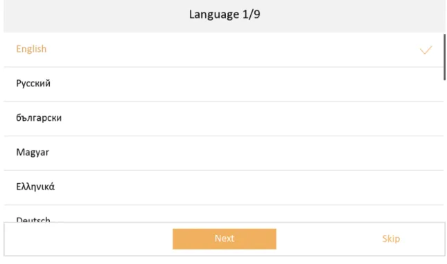
1. Choose language and tap Next.
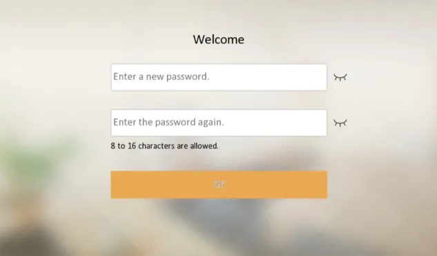
Figure 3-1 Language Settings 2. Activate the device. Create a password and confirm it. Tap OK.
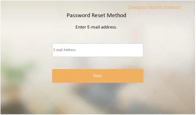
Figure 3-2 Activate 3. Set password reset methods and tap Next.
Figure 3-3 Password Reset Page
- Bind an email address. If you forget your admin password (activation password), you can change the password via the reserved email address.
Network Indoor Station Configuration Guide
- (Optional) Tap Change to Security Question to select security questions and enter the answers. If you forget your admin password (activation password), you can change the password via answering the questions.
4. Set Wi-Fi.
1) Enable the Wi-Fi function. The searched Wi-Fi will be displayed in the list.
2) Select a Wi-Fi and enter the Wi-Fi's password.
3) Tap Next.
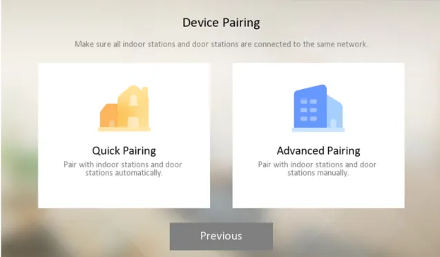
Figure 3-4 Wi-Fi Settings 5. Device pairing.
Figure 3-5 Select Device Pairing Mode
- Quick pairing: The indoor station and the door station will be paired automatically.
1. Set the indoor station's room No. and tap Next.
2. Select the door station that you need to connect. The door station with the same LAN as the indoor station will be displayed in the list.
Note
If select multiple door stations, uncheck the main door station, and tap Main to change a main door station, and the others are sub door stations.
3. Select the indoor extension that need to connect. The indoor extension with the same LAN as the indoor station will be displayed in the list.
- Advanced Pairing: The indoor station and the door station should be paired manually.
1. Set the indoor station's floor No., room No., build No., unit No.
2. Set the indoor station's wired network parameters, you can choose to enable DHCP or manually set the IP address, subnet mask, and default gateway.
3. Select the door station that you need to connect. The door station with the same LAN as the indoor station will be displayed in the list.
Note
If select multiple door stations, uncheck the main door station, and tap Main to change a main door station, and the others are sub door stations.
Network Indoor Station Configuration Guide
4. Select the indoor extension that you need to connect. The indoor extension with the same LAN as the indoor station will be displayed in the list.
6. After the devices are paired, tap Test. The video intercom will be completed is the devices are connected properly.
7. Configure the Hik-Connect service settings. After you enable the function, you can control the video intercom device via the mobile App.
1) Enable Hik-Connect service.
2) Edit verification code or use the activation password by default.
3) View Hik-Connect Server Status.
4) Scan the first QR Code to download the APP of Hik-Connect. Scan the second QR Code to add your device to the APP. After adding the device to the APP, you can configure the device remotely.
5) Tap Next.
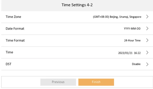
Figure 3-6 Hik-Connect Service Settings 8. Set time and tap Next.
1) Select the Time Zone.
2) Tap Date Format and Time Format to set the time format, which will displayed on the home page.
3) Tap Time to set time manually.
4) Enable DST.Set the DST start time, end time and bias time.
Figure 3-7 Time Settings 9. Tap Finish to complete the settings.
3.2 Quick Operation (For Normal Device)
After device activation, the wizard page will pop up. The description is for other indoor stations.
Steps
1. Choose language and tap Next.
Network Indoor Station Configuration Guide
Figure 3-8 Language Settings 2. Set password reset methods and tap Next.
- Bind an email address. If you forget your admin password, you can reset the password via the reserved email address.
- Tap Change to Security Question to select security questions and enter the answers. If you forget your admin password, you can reset the password via answering the questions.
Figure 3-9 Password Reset Methods 3. Set network parameters and tap Next.
- Edit Local IP, Subnet Mask and Gateway parameters manually.
- Enable Auto Get IP address, the device will get network parameters automatically.
Figure 3-10 Network Parameters
Network Indoor Station Configuration Guide
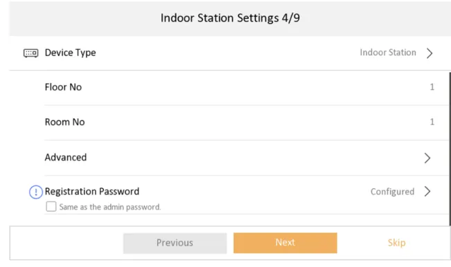
4. Configure the indoor station.
1) Select Device Type as Indoor Station or Indoor Extension.
2) Set Floor No..
3) Set Room No..
4) Configure advanced settings. Set Comminity No., Building No. and Unit No.
5) Set Registration Password.
6) Tap Next.
Figure 3-11 Indoor Station Settings
5. Enable the Wi-Fi function. Select a Wi-Fi from the list and enter the Wi-Fi's password to get connected. Tap Next.
Note
The device should support Wi-Fi.
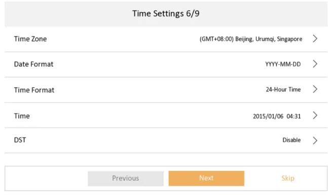
Figure 3-12 Wi-Fi 6. Set time and tap Next.
1) Select the Time Zone.
2) Tap Date Format and Time Format to set the time format.
3) Tap Time to set time manually.
4) Enable DST.Set the DST start time, end time and bias time.
Network Indoor Station Configuration Guide
Figure 3-13 Time Settings 7. Configure the Hik-Connect service settings.
1) Enable Hik-Connect service.
2) Edit verification code or use the activation password by default.
3) View Hik-Connect Server Status.
4) Scan the first QR Code to download the APP of Hik-Connect. Scan the second QR Code to add your device to the APP. After adding the device to the APP, you can configure the device remotely.
5) Tap Next.
Figure 3-14 Guarding Vision Service Settings
8. Link related devices and tap Next. If the device and the indoor station are in the same LAN, the device will be displayed in the list. Tap the device or enter the serial No. to link.
Figure 3-15 Related Device 1) Tap the door station in the list to link.
Network Indoor Station Configuration Guide
Note
If the door station is inactive, the system will pop up the dialog to activate the door station.
2) Edit the network parameters of the door station manually.
3) Tap Next.
9. Optional: Enable Indoor Station and link related indoor extension devices. Tap Finish. If the indoor extension and the indoor station are in the same LAN, the device will be displayed in the list. Tap the device or enter the serial No. to link.
Figure 3-16 Related Device 1) Tap the door station in the list to link.
Note
If the indoor extension is inactive, the system will pop up the dialog to activate the device.
2) Edit the network parameters of the indoor extension manually.
10. Tap Finish to save the settings.
3.3 Basic Settings
Basic settings is required before starting using the indoor station. It is necessary to set the indoor station network, room No., linked devices, device time display, and so on.
3.3.1 Set Indoor Station Network Parameters
Network connection is mandatory for the use of the indoor station. Set the network parameters after activating the indoor station. Only when the IP address of the indoor station is in the same network segment as other devices, it can work properly in the same system.
Steps Note
The default IP address of the indoor station is 192.0.0.64.
Two ways are available for you to set IP address: DHCP, and set IP address manually.
1. Tap Settings → → Configuration , and enter admin (activation) password.
2. Tap to enter the network settings page.
Figure 3-17 Network Settings 3. Set the network parameters.
- Enable DHCP, and the system can assign an IP address of the indoor station automatically.
- Disable the DHCP function, and set the IP address manually. You should set the device IP address, the gateway, the DNS address.
Network Indoor Station Configuration Guide
3.3.2 Set Linked Device IP
Linked network parameters refers to the network parameters of devices (like door station,
doorphone, main station, center, etc.), to which the indoor station is linked. Linked devices for the indoor station refers to door station, center, main station, and doorphone.
With the private SIP protocol, intercom can be realized only when all these devices are in the same network segment with the indoor station.
With the standard SIP protocol, intercom can be realized when all these devices support the standard SIP protocol.
Steps Note
● The doorphone does not support adding with the standard SIP protocol.
● Here take main door station network settings as example.
1. Tap Settings → → Configuration → to enter the device management page.
Note
Default admin password is the activation password.
2. Tap Main Door Station to pop up the device information dialog.
3. Select a device to link. Edit the following parameters.
Name
You can edit the name of the device.
Language
Select a language from the drop-down list for the device.
Network
Enable Auto Get IP Address and the system will assign IP address, subnet mask, and gateway automatically. Or edit the IP address, subnet mask, and gateway manually.
Door Lock Parameters
After wire the lock with the door station, you can set name and door opening duration according to your needs.
Note
Up to 2 locks can be configured.
Volume Settings
Set microphone volume and output volume.
Call Number Settings
The call No. should be the same as the indoor station's room No. If press the call button of the door station, you can call the indoor station directly.
Public Password
You can use the public password to open the door station related door lock. Select the public password type. Enter the old password and new password and then confirm the new
password. Tap OK to save the settings.
Restore to Default Settings Restore All
All parameters will be restored to the factory settings. The system will reboot to take effect.
Device Reboot
Reboot the device.
3.3.3 Set Wi-Fi
Some indoor station support Wi-Fi connection.
Note
Parts of models support setting Wi-Fi. For details, refers to actual product.
Network Indoor Station Configuration Guide
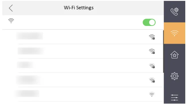
Tap Settings → to enter the Wi-Fi Settings page. Enable Wi-Fi. Select a Wi-Fi from the list and enter the password of the Wi-Fi, and the indoor station can connect to the Wi-Fi.
Figure 3-20 Wi-Fi Settings
3.3.4 Set Indoor Station No.
Indoor station No. and the indoor extension No. are numbers, which can be dialed by other devices to call the indoor station and the indoor extension in an intercom system. The indoor station No., is composed of the floor No., room No., community No., building No. and unit No.
The indoor extension No. Should be a numeric from 1 to 5.
Up to 5 indoor extensions can be set for 1 indoor station.
Steps
1. Tap Settings → → Configuration → to enter the indoor station No. settings page.
Note
Default admin password is the activation password.
Figure 3-21 Set Indoor Station No.
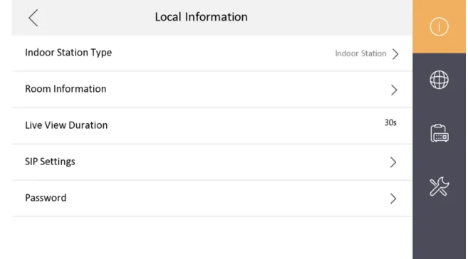
2. Select Indoor Station to set the room information, live view duration, SIP parameters and password.
Room Information
You can set room name, floor No., and room No. Tap Advanced Settings to set community No., building No. and unit No. if you need.
Note
● Community No., building No., and unit No. can be omitted if there is no such information.
● If there are two indoor stations that are in the same building, and should call each other, enter the the room No. directly to call.
● If there are two indoor stations that are in two buildings, and should call each other, enter the building No. and the room No. to call. For examle, call 1-405 to call room 405 in building 1.
Live View Duration
You can set the duration of live view.
SIP Settings
You can set SIP parameters. For more details, please refer to: SIP Settings Password Settings
You can set unlock password and duress code.
3. Select Indoor Extension to set the room information, live view duration, registration password and enable SIP 1.0 according to your needs.
Network Indoor Station Configuration Guide
Room Information
You can set room name and No. Tap Advanced to set the community No., building No., and unit No. if you need.
When calling the indoor station and the two devices are in the same building, you can call the room No. directly.
If
Live View Duration
You can set the duration of live view.
Registration Password
You can create a new SIP registration password.
Enable SIP 1.0
You can enable SIP 1.0 protocol according to your needs.
3.3.5 SIP Settings
Devices can communicate with each other via SIP protocol. You create set the SIP register password, enable standard SIP and set VOIP account.
Steps
1. Tap Settings → → Configuration , and enter admin (activation) password.
2. Tap SIP Settings in Local Information Page.
3. Set SIP registration password.
1) Tap Registration Password.
2) Create a new SIP registration password and confirm the password.
3) Tap OK.
4. Optional: Enable Compatible with SIP 1.0 Indoor Station and the indoor station (SIP 2.0) can be compatible with SIP 1.0 indoor station.
5. Optional: Enable standard SIP and you can access to the third party devices.
1) Slide to Enable Standard SIP.
2) Tap VOIP Account Settings and configure the account information, including the user name, the phone number, the registered user name, the password, the domain, the port No., and the expiration date.
Figure 3-23 VOIP Account Settings Note
Up to 32 characters are allowed in the user name.
3.3.6 Add Camera
Steps
1. Tap Settings → → Configuration , and enter admin (activation) password.
2. Tap to enter the device management page.
3. Tap + to pop up the dialog box.
4. Select a protocol to add the camera.
- Select HIK Protocol and you can add the camera depended on the HIK protocol.
Network Indoor Station Configuration Guide
Enter the device name, IP address, user name and the password of the camera. Edit port No.
and channel No.
Exit the page to save the settings.
- Select Open Network Video Interface to add the camera.
Enter the device name, IP address, user name and the password of the camera.
Exit the page to save the settings.
3.3.7 Zone and Alarm Settings
Zone Settings
You can set the zone type, alarm type and delay time and other parameters of 8 zones.
Before You Start
Tap Settings → → Shortcut Settings , and enable Alarm.
Steps Note
Arming status page and zone settings page are hidden by default. You should enable alarm function first.
1. Tap Settings → → Zone Settings to enter the zone settings page.
2. Press a zone to pop up the zone editing dialogue box.
3. Set the zone type, alarm type, status of arming status, entering delay, and exiting delay.
4. Tap OK to save the settings.
Note
● 7 zone types are selectable: Panic Button, Door Magnetic, Smoke Detector, Active Infrared, Passive Infrared, Gas Detector, and Doorbell.
● 3 alarm types are selectable: 24h Alarm, Instant Alarm, and Delay Alarm.
Set the alarm type as 24h alarm, and the zone will be armed for 24h.
Set the alarm type as instant alarm, and the zone will alarm once it's triggered.
Set the alarm type as delay alarm, and you should set the entering delay duration and exiting delay duration.
● Both the entering delay duration and the exiting delay duration are from 30s to 60s.
● For Gas Detector, Smoke Detector and doorbell, the alarm type is set as default 24h alarm.
The alarm type of them can not be changed.
Arming Mode Settings
4 arming modes can be configured: stay mode, away mode, sleeping mode and custom mode.
Before You Start
Tap Settings → → Shortcut Settings to enable Alarm.
Steps Note
On the home page, the arming status function and zone settings function are hidden by default.
You should enable the alarm function first.
1. Back to the home page, tap Settings → → Scene Settings to enter the arming mode settings page.
2. Tap Stay Mode, Away Mode, Sleeping Mode, or Custom to enter the page.
Network Indoor Station Configuration Guide
Figure 3-25 Arming Mode Settings 3. Arm the selected zone.
Note
● Zones are configurable on the arming mode page.
● 24H alarm zone including smoke detector zone and gas detector zone will be triggered even if they are disabled.
● Arming mode settings should be configured with the settings of arming status on the user page of the device.
3.4 Password Settings
3.4.1 Change Admin Password
If you forget admin (activation) password when entering Configuration page, you can change it via verification code from Email.
Steps
1. Tap Settings → → Configuration , to enter the Admin Password page.
2. Tap Forgot Password.
3. Download the APP of Hik-Connect and run Hik-Connect client software.
4. Scan the QR code via Hik-Connect.
5. Open the E-mail to get the verification code.
6. Tap Next, and enter the verification code from the E-mail.
7. Tap Next, and create the new password.
Note
The new password is used for admin login, remote SDK login, SSH login, and Web login.
3.4.2 Security Settings
If you forgot the admin password, you can change your password via the reserved email address or the security questions.
Steps
1. Tap Settings → → Configuration , and enter the admin (activation) password to enter the local information page. Tap → Security Settings to enter security setting page.
2. Tap Email Address. Enter or edit the address.
3. Tap Security Question. Select questions and enter the answers.
4. After the settings, you can reset your password via the reserved email address or via answering questions.
3.4.3 Modify Arm/Disarm Password
You can create and edit the arm/disarm password of the indoor station.
Steps
1. Tap Settings → → Password to enter the settings page.
Network Indoor Station Configuration Guide
Figure 3-26 Arm/Disarm Password Settings
2. Create the indoor station's arm/disarm password. You should enter the arm/disarm password to enable or disable the function.
3. When you slide to disable Scene Password, there is no needs to enter password during scene mode switching.
3.4.4 Modify Unlock/Duress Code
You can create and edit the duress code and unlock password of the indoor station.
Steps
1. Tap Settings → → Configuration , and enter admin (activation) password.
2. Tap Password.
Figure 3-28 Unlock and Duress Code Settings Page
3. Tap Unlock Password or Duress Code to pop up the password settings dialog box.
Unlock Password
Create the indoor station's unlock password. If the device has connected to a lock, enter the password to unlock.
Duress Code
When you are hijacked and forced to open the door, you can enter the duress code. An alarm will be triggered to notify the management center secretly.
Note
The duress code and the unlock password cannot be the same.
4. Create a new password and confirm it.
5. Tap OK to save the settings.
Network Indoor Station Configuration Guide
3.5 Synchronize Time
Steps
1. Tap Settings → → Time and Date to enter the time synchronization page.
2. Tap Date Format and Time Format to set the time format.
3. Optional: Tap Time to set time manually.
4. Tap Sync Tim.
Figure 3-29 Time Synchronization 1) Select the Time Zone.
2) Enable Enable NTP.
3) Set the synchronizing interval, enter the IP address/domain of NTP server and port No.
Note
● The default unit of synchronizing interval is minute.
● The time zone can be configured as well if the NTP is not enabled.
3.6 Sound Settings
Set the ringtone sound, the volume, and the auto answer.
3.6.1 Call Settings
You can set the ringtone, ring duration, call forwarding time on call settings page.
Steps
1. Tap Settings → to enter the call settings page.
Figure 3-30 Call Settings 2. Set corresponding parameters.
Ringtone
There are 3 ringtones by default, and you can custom and import at most 4 ringtones via Batch Configuration Tool or iVMS-4200 Client Software.
Ringtone Duration: The maximum duration of indoor station when it is called without being accepted. Ringtone duration ranges from 30 s to 60 s.
Calling Duration
The call will end automatically when the actual calling duration is longer than the configured one. Calling duration ranges from 30 s to 60 s.
Call Forwarding Duration
The ring duration limit beyond which the call is automatically forwarded to the mobile phone designated by the resident. Call forwarding ranges from 0 s to 20 s.
Other Settings
You can set the Do Not Disturb and Auto-answer functions.
Network Indoor Station Configuration Guide
Auto-answer
Enable Auto-answer. After enabling, the call from door station/villa door station will be answered by the indoor station automatically. The caller from door station/villa door station can leave voice messages. After the message is left, you can check it from Message on the main page of the device.
Figure 3-31 Main Page Note
Before enabling Auto-answer, the function of Leave Message needs to be enabled. Tap Settings → → to enter the shortcut settings page. Eanble Leave Message and go back to calling settings page to enable Auto-answer.
Do Not Disturb Device
Select All and all devices will not disturb this device. Select Indoor Station and all indoor station will not disturb this device.
Do Not Disturb
Set the do not disturb schedule. Select Close and the do not disturb function will not be enabled. Select All Day and this device will not be disturbed all day. Select Schedule and you can set the do not disturb time duration. Within the configured time, this device will not be disturbed.
Note
Indoor extension does not support the ring duration settings, call forwarding settings, or auto- answer function.
3.6.2 Volume Settings
Set the microphone volume, prompt sound volume, call volume, and enable touch sound.
Steps
1. Tap Settings → → Volume Settings to enter the volume settings page.
2. Set the microphone volume, prompt sound volume, and the call volume. You can also enable Touch Sound to turn on the key sound.
3.7 Via the mobile client
The device support adding to Hik-Connect and cofiguration remotely via the client.
3.7.1 Link to the Mobile Client
Download and link to the mobile client, and you can configure the parameters of the device remotely via mobile client.
Steps
1. Tap Settings → → Configuration and enter the admin (activation) password to enter the settings page.
2. Tap to enter the system maintenance page.
3. Tap Hik-Connect Service Settings.
Network Indoor Station Configuration Guide
Figure 3-33 Hik-Connect Service Settings Page 4. Enable Enable Hik-Connect Service.
5. Edit LBS server and Verification Code.
Note
● Verification code is used to add the device to mobile client.
● You can tap to enable or disable verification code reveal.
6. View the service status on the page.
7. Optional: Scan the QR code on the screen.
Note
● Scan the left QR code on the screen to download Hik-Connect.
● Scan the right QR code on the screen to add the device to the mobile client.
3.7.2 Unlink the Account
Remove the account from the mobile client.
Steps
1. Tap Settings → → Configuration , and enter the admin (activation) password.
Figure 3-34 System Maintenance (For DS-KH6320EY-WTE2 Indoor Stations)
Figure 3-35 System Maintenance (For Normal Indoor Stations) 3. Tap Unlink App Account, and follow the steps on the page.
Network Indoor Station Configuration Guide
3.8 System Settings
You can format or install TF card, clear the screen, view the version information of the indoor station and reboot the system on the settings page.
General Settings
Tap Settings → to enter the general settings page.
Figure 3-36 General Settings Page Time and Date
Set the displayed time and date format, current time. Tap Sync Time and enable NTP to
synchronize the device time. You can also enable DST and set the DST start time, end time and bias.
Note
● Make sure your device is connected with the network or the NTP function will not available.
● For details, see Synchronize Time . System Language
Tap System Language to change the system language.
Brightness Adjustment
Tap + or - to adjust the screen brightness.
Clean Screen
Enable Clear Screen and the screen will be locked for 30s. And you can clear the screen within the time duration.
Note
● After enabling Clear Screen function, press and hold the Unlock key to exit the clear screen mode.
● The device without unlock key will exit the clear screen mode automatically when the time is out.
TF Card
Tap TF Card to view the TF card and you can also format the TF card.
Reboot
Tap Settings → to enter the advanced settings page.
Tap Reboot Device to reboot the deivce immediately.
System Maintenance
Tap Settings → → Configuration , and enter the admin (activation) password.
Tap to enter the system maintenance page.
Figure 3-37 System Maintenance (For DS-KH6320EY-WTE2 Indoor Stations)
Network Indoor Station Configuration Guide
Figure 3-38 System Maintenance (For Normal Indoor Stations) Upgrade
Tap Upgrade to get the upgrade package online and reboot automatically.
Restore (For DS-KH6320EY-WTE2)
Figure 3-39 Restore Page (For DS-KH6320EY-WTE2) Restore All
Restore all parameters of the indoor station to factory settings and the system will reboot automatically.
Restore Video Intercom System
All devices in the video intercom system (the indoor station and its linked devices) will be restored to the factory settings. And the system will reboot automatically.
Restore Linked Indoor Extension
Restore all parameters of the linked indoor extension to factory settings and the system will reboot automatically.
Restore Linked Door Station
Restore all parameters of the linked door station to factory settings and the system will reboot automatically.
Restore (For Normal Indoor Station) Restore Default Settings
Tap Restore Default Settings to restore parameters except network parameters and activation password to factory settings. And the system will reboot automatically.
Restore All
Tap Restore All to restore all parameters to factory settings and the system will reboot automatically.
Network Indoor Station Configuration Guide
Wizard
Tap Wizard and set the language, network, indoor station type, device No., and select a device according to the wizard. Refers to Quick Operation (For Normal Device) for the details.
Preference
Tap Settings → to enter the preference page.
Shortcut Settings
Enable call elevator, alarm, call management center, or leave message and the icon will be displayed on the home page.
Zone Settings Note
Only when enable Alarm in the shortcut settings, can the Zone Settings displayed on the Preference page.
Set the zone parameters. For details, see Zone Settings . Scene Settings
Note
Only when enable Alarm in the shortcut settings, can the Scene Settings displayed on the Preference page.
Set the scene parameters, including the stay mode, the away mode, the sleeping mode, or customize the scene. For details, see Arming Mode Settings .
3.9 Output Settings
You can set and control the connected output devices via the output settings page. You can change the relay' name, and open duration. You can also set to display the relay button on the main page or not.
Steps
1. Tap Settings → → Output Settings . Note
● Supports up to 2 relays.
● If no relays displayed on the page, the device may not support the function.
2. Select a relay and set the parameters.
Note
1 to 32 characters are allowed. Supports uppercase letters, lowercase letters, numerics, and special characters.
Remain Open
Enable the function, the relay remains open.
Disabled the function, and you can set the remain open duration.
Note
● By default, the function is disabled.
● 1 to 180 s are available to set.
Hide on Main Page
Enable the function and the relay button will be displayed on the main page. You can control the relay status manually on the main page.
Disabled the function and the relay button will no be displayed on the main page.
3.10 Device Information
View the device information, including the version, model, serial No. and open source disclaimer.
Steps
1. Tap Settings → → Device Information to enter the Device Information page.
2. View the device version, model, and serial No.
3. Optional: Tap Open Source Disclaimer to view the OSS statement.
Network Indoor Station Configuration Guide
Chapter 4 Remote Operation via the Client Software
The Video Intercom module provides remote control and configuration on video intercom products via the iVMS-4200 client software.
4.1 Device Management
Device management includes device activation, adding device, editing device, and deleting device, and so on.
After running the iVMS-4200, video intercom devices should be added to the client software for remote configuration and management.
4.1.1 Add Video Intercom Devices
Steps Note
● You can add at most 512 indoor stations and main stations in total to the client, and add at most 16 door stations to the client.
● For video intercom devices, you are required to create the password to activate them before they can be added to the software and work properly.
● You can add online video intercom devices, and add them manually. Here take adding online video intercom devices as example.
1. Click Maintenance and Management → Device Management to enter the device management page.
2. Click the Device tap.
3. Click Add to add the device to the client.
Figure 4-1 Add the Device
4. Optional: Click Online Device, the active online devices in the same local subnet with the client software will be displayed on the Online Device area.
Network Indoor Station Configuration Guide
Note
To add online devices to the software, you are required to change the device IP address to the same subnet with your computer first.
1) You can click Refresh Every 60s to refresh the information of the online devices.
2) Select the devices to be added from the list.
3) Click Add to Client to add the device to the client.
5. Input the required information.
Nickname
Edit a name for the device as you want.
Address
Input the device's IP address. The IP address of the device is obtained automatically in this adding mode.
Port
Input the device port No. The default value is 8000.
User Name
Input the device user name. By default, the user name is admin.
Password
Input the device password.
6. Optional: You can check the checkbox Export to Group to create a group by the device name. All the channels of the device will be imported to the corresponding group by default.
The client also provides a method to add the offline devices. Check the checkbox Add Offline Device, input the required information and the device channel number and alarm input number, and then click Add. When the offline device comes online, the software will connect it
automatically.
Note
● Add Multiple Online Devices: If you want to add multiple online devices to the client software, click and hold Ctrl key to select multiple devices, and click Add to Client to open the device adding dialog box. In the pop-up message box, enter the user name and password for the devices to be added.
● Add All the Online Devices: If you want to add all the online devices to the client software, click Add All and click OK in the pop-up message box. Then enter the user name and password for the devices to be added.
4.1.2 Modify Network Information
Note
You should enter the admin password of the device in the Password field of the pop-up window to modify the parameters.
4.2 System Configuration
You can configure the video intercom parameters accordingly.
Steps
1. Click Maintenance and Management → System Configuration → ACS & Video Intercom to enter the system configuration page.
2. Enter the required information.
Ringtone
Click ... and select the audio file from the local path for the ringtone of indoor station.
Optionally, you can click for a testing of the audio file.
Ringtone Duration
Enter ringtone duration, ranging from 15 seconds to 60 seconds.
Max. Speaking Duration with Indoor Station
Enter the maximum duration of speaking with the indoor station, ranging from 120 seconds to 600 seconds.
Max. Speaking Duration with Door Station
Enter the maximum duration of speaking with the door station, ranging from 90 seconds to 120 seconds.
Max. Speaking Duration with Access Control Device
Enter the maximum duration of speaking with the access control device, ranging from 90 seconds to 120 seconds.
3. Click Save to enable the settings.
4. Optional: Click Default to restore the default parameters.
4.3 Remote Configuration
In the device list area, select a device and click to enter the remote configuration page.
4.3.1 System
Click System on the remote configuration page to display the device information: Device Information, General, Time, System Maintenance, User, RS-485, and Security.
Network Indoor Station Configuration Guide
Device Information
Click Device Information to enter device basic information page. You can view basic information (the device type, and serial No.), and version information of the device.
Figure 4-2 Device Information
General
Click General to enter device general parameters settings page. You can view and edit the device name and device ID, and select overwrite record file.
Figure 4-3 General
Figure 4-4 Time Settings Page
Select Time Zone, Enable NTP, Enable DST, or SDK Synchronization. Click Save to save the time settings.
● Time Zone: Select a time zone from the drop-down list menu.
● NTP: Click Enable NTP, and enter the server address, NTP port, and synchronization interval.
Note
The default port No. is 123.
● DST: Click Enable DST, and set the start time, end time, and bias.
● SDK Synchronization: Click Synchronization, and the system will synchronize the data to the SDK.
System Maintenance
Click System Maintenance to enter the page.
Network Indoor Station Configuration Guide
Figure 4-5 System Maintenance
● Reboot: Click Reboot and the system reboot dialog box pops up. Click Yes to reboot the system.
● Restore Default Settings: Click Restore Default Settings to restore the default parameters. All default settings, excluding network parameters, will be restored.
● Restore All: Click Restore All to restore all parameters of device and reset the device to inactive status.
Note
all default settings, including network parameters, will be restored. The device will be reset to inactivated status.
● Import Configuration File: Click Import Configuration File and the import file window pops up.
Select the path of remote configuration files. Click Open to import the remote configuration file.
The configuration file is imported and the device will reboot automatically.
● Export Configuration File: Click Export Configuration File and the export file window pops up.
Select the saving path of remote configuration files and click Save to export the configuration file.
● Remote Upgrade: Click ... to select the upgrade file and click Upgrade to remote upgrade the device. The process of remote upgrade will be displayed in the process bar.
Note
○ The device supports 19 languages: English, French, Brazilian Portuguese, Spanish, Russian, German, Italian, Polish, Arabic, Turkish, Vietnamese, Ukrainian, Hungarian, Dutch, Romanian, Czech, Bulgarian, Croatian, Serbian.
○ Rebooting the device is required after you change the system language.
User
Click User to enter the user information editing page.
Select the user to edit and click Edit to enter the user parameter page.
Figure 4-6 User Page Note
● The new password and confirm password should be identical.
● After editing the password of device, click refresh button from the device list, the added device will not be there. You should add the device again with new password to operate the remote configuration.
Network Indoor Station Configuration Guide
RS-485
Click RS485 to enter the RS-485 settings page. You can view and edit the RS-485 parameters of the device.
Figure 4-7 RS-485 Settings Note
For indoor station and main station, there are 3 choices for the working mode: transparent channel, disable, and custom.
Security
Click Security to enter the page. You can enable SSH or enable HTTPS on this page.
Click Save after configuration.
Figure 4-8 Security
4.3.2 Video Intercom
Click Video Intercom on the remote configuration page to enter the video intercom parameters settings: Time Parameters, Password, Zone Configuration, IP Camera Information, Volume Input and Output Configuration, Ring, Arming Information, Calling Linkage, Relay, and SIP No.
Time Parameters
Steps
1. Click Time Parameters to enter time parameters settings page.
Network Indoor Station Configuration Guide
Figure 4-9 Time Parameters
2. Configure the calling duration, live view duration, call forwarding time, and the ringtone duration.
3. Click Save.
Note
● Calling duration is the maximum duration of indoor station when it is called without being received. The range of maximum ring duration varies from 30s to 60s.
● Live view duration is the maximum time of playing live view of the indoor station. The range of maximum live view time varies from 10s to 60s.
● Call forwarding refers to the ring duration limit beyond which the call is automatically
forwarded to the mobile phone designated by the resident. The range of call forwarding time varies from 0s to 20s.
● For indoor extension, it only requires setting the maximum live view time.
Permission Password
Click Permission Password to enter password changing page.
Figure 4-10 Permission Password For indoor station, you can change the arm/disarm password.
Zone Alarm
Steps
1. Click Zone Alarm to enter the zone settings page.
Network Indoor Station Configuration Guide
Figure 4-11 Zone Alarm 2. Select Area No.
3. Select Zone Type from the drop-down list.
4. Select Alarm Type from the drop-down list.
5. Set the NO/NC status.
6. Set Entering Delay and Exiting Delay.
7. Click Save to enable zone settings.
Note
● 7 zone types are supported: Emergency Switch, Door Magnetic Switch, Smoke Detector, Active IR Detector, Passive IR Detector, Combustible Gas Detector, and DoorBell Switch.
● 3 types of alarm mode are supported: Instant Alarm, 24H Alarm, and Delay Alarm.
● When the zone type is set to be Instant Alarm, only under arming mode, the indoor station
● When the zone type is set to be 24H Alarm, the indoor station will receive alarm message when the detector is triggered no matter it is under arming mode or disarming mode.
● When the zone type is set to be Delay Alarm, only under arming mode, the indoor station will receive alarm message when the detector is triggered. Under disarming mode, it will not receive alarm message when the detector is triggered.
● After setting enter delay time, if OK is pressed within the enter delay time after the alarm, the alarm event will not be uploaded to the management center; if OK is not pressed within the enter delay time after the alarm, the alarm event will be uploaded to the management center.
● The exit delay is the time between you enable the arming mode and the arming takes effect.
Network Camera Information
You can add, delete and edit cameras that can be added to the video intercom products, with two ways of getting stream: direct or URL. By exporting and importing the added device information, you can edit added devices parameters in batch.
Add Camera
Steps
1. Click IP Camera Information to enter IP camera information page.
Figure 4-12 IP Camera Information 2. Click Add to pop up the device adding dialog box.
3. Enter corresponding information (device name, IP address, port No., user name, password, etc.), and click OK.
Note
Indoor extension does not support this function.
Export and Import Added Device Information
Steps
1. Click Export to export the added device information file.
2. Edit parameters of added devices in batch in the exported file.
3. Click Import to pop up importing box, and open the edited added device information file.
Network Indoor Station Configuration Guide
Figure 4-13 Import Added Device Information
Volume Input and Output
Steps
1. Click Volume Input/Output to enter the configuring the volume input or output page.
Figure 4-14 Volume Input or Output
2. Slide the slider to adjust the input volume, output volume and speak volume.
3. Click Save to enable the settings.
Ring Import
Steps
1. Click Ring Import to enter the ring configuration page.
Figure 4-15 Ring Import 2. Click + to add the ring, and click x to delete the imported ring.
Network Indoor Station Configuration Guide
Note
● The ring to be imported should be in the wav format, and the size of the ring cannot be larger than 300k.
● Up to 4 rings can be added.
Arming Information
Click Arming Information to enter the configuring arming informaton page and view the arming information.
Figure 4-16 Arming Information Click Refresh to refresh the arming information.
Relay
Some indoor station devices support this function.
Click Relay to enter the set relay parameters page.
Select a relay and click " " and set the relay name and output delay time. Click Save to enable the settings.
Click Copy to..., and select a relay you want to copy to. Click Save to enable the settings.
SIP No. Settings
Steps
1. Click SIP No. Settings to enter the settings page.
Figure 4-17 Extension Settings 2. Click Add.
Network Indoor Station Configuration Guide
4. Enter the required information.
Serial No.
Enter the device's serial No.. The serial No. is on the rear panel of the device (A fixed-length number with 9 digits).
IP Address
Enter the device's IP address.
Gateway
Enter the device's gateway.
Subnet Mask
Enter the device's subnet mask.
Password
Enter the device password, ranging from 8 to 16 characters in length.
No.
Enter the device No., ranging from 1 to 5.
5. Click Save to enable the settings.
6. Set SIP information.
Click Configure Configure serial No., IP address, gateway, subnet mask, password and No. of the device.
Click Delete Delete the SIP Number.
Click Clear Clear all SIP numbers.
Click Refresh Refresh SIP Information.
4.3.3 Network
Local Network Configuration
Steps
1. Click Local Network Configuration to enter the configuring the local network parameters page.
Network Indoor Station Configuration Guide
Figure 4-19 Local Network Configuration
2. Enter the Local IP Address, IP Address Subnet Mask, Gateway, Port No. and HTTP Port No.
3. Click Save to enable the settings.
Note
● The default port No. is 8000.
● After editing the local network parameters of device, you should add the devices to the device list again.
SIP Server Configuration
Steps
1. Click SIP Server Configuration to enter the configuring the SIP parameters page.
Figure 4-20 SIP Server Configuration 2. Click Enable.
3. Set the parameters according to your needs.
Note
● Up to 32 characters are allowed in the Register User Name field.
● Registration password should be 1 to 16 characters in length.
● Up to 32 characters are allowed in the Number field.
● The device location should contain 1 to 32 characters.
● The registration period should be between 15 minutes to 99 minutes.
4. Click Save to enable the settings.
DNS Settings
The indoor station supports 2 DNS address.
Click Advanced Settings to enter DNS address settings page.
Edit the IP address and click Save.
Network Indoor Station Configuration Guide
Figure 4-21 DNS Settings
Configure Mobile Client Connection
Configure Hik-Connect server parameters before viewing videos via mobile client.
Before You Start
Make sure the indoor station connects to the network.
Steps
1. Click Hik-Connect to enter the configuring the settings page.
2. Enable Enable Hik-Connect.
Note
● To enable Hik-Connect service, you need to create a verification code or change the verification code.
● The verification code should be 6 to 12 letters or numbers, case sensitive. You are recommended to use a combination of no less than 8 letters or numbers.
3. Enter the Verification Code and confirm the verification code.
4. Click OK.
5. Enable Custom and edit Service Address.
6. If you forget the verification code, you can enable View.
7. Click Save to enable the settings.
8. Optional: Click Refresh to refresh the settings.
Group Network Settings
Click Group Network Settings to enter the group network settings page.
Figure 4-22 Group Network Settings
Device No. Settings
Select the device type from the drop-down list, and set the corresponding information.
Note
● Device type can be set as indoor station or indoor extension.
● When you select indoor extension as device type, the device No. can be set from 1 to 5.
Click Save to enable the settings.
Linked Device Network Settings
Enter Registration Password and set the corresponding information.
Note
● D series refers to door station, and V series refers to villa door station.
● Registration password is the password of the SIP server.
4.4 Person Management
You can add, edit, and delete the organization and person in Person Management module.
Organization and person management is necessary for the video intercom function.
On the main page, click Person to enter the page.
Network Indoor Station Configuration Guide
Figure 4-23 Personal Management Application
The page is divided into two parts: Organization Management and Person Management.
Organization Management You can add, edit, or delete the organization as desired.
Person Management After adding the organization, you can add the person to the organization and issue card to persons for further management.
4.4.1 Organization Management
On the main page of the Client Software, click Person to enter the configuration page.
Add Organization
Steps
1. In the organization list on the left, click +Add.
2. Input the organization name as desired.
3. You can add multiple levels of organizations according to the actual needs.
1) You can add multiple levels of organizations according to the actual needs.
Note
Up to 10 levels of organizations can be created.
Modify and Delete Organization
You can select the added organization and click to modify its name.
You can select an organization, and click X button to delete it.
Note
● The lower-level organizations will be deleted as well if you delete an organization.
● Make sure there is no person added under the organization, or the organization cannot be deleted.
4.4.2 Person Management
After adding the organization, you can add person to the organization and manage the added person such as issuing cards in batch, importing and exporting person's information in batch, etc.
Note
Up to 10,000 persons or cards can be added.
Add Person
Person information is necessary for the video intercom system. And when you set linked device for the person, the intercom between intercom devices can be realized.
Steps
1. Select an organization in the organization list and click +Add on the person panel to pop up the adding person dialog.
Note
The Person ID will be generated automatically and is editable.
2. Set basic person information.
1) Enter basic information: name, tel, birthday details, effective period and email address.
2) Optional: Click Add Face to upload the photo.
Note
The picture should be in *.jpg format.
Click Upload Select the person picture from the local PC to upload it to the client.
Network Indoor Station Configuration Guide
Click Take Phone Take the person's photo with the PC camera.
Click Remote Collection Take the person's photo with the collection device.
3. Issue the card for the person.
1)