Number 7 SMITHSONIAN ANNALS OF FLIGHT
SMITHSONIAN AIR AND SPACE MUSEUM
S E R I A L P U B L I C A T I O N S O F T H E S M I T H S O N I A N I N S T I T U T I O N The emphasis upon publications as a means of diffusing knowledge was expressed by the first Secretary of the Smithsonian Institution. In his formal plan for the Insti- tution, Joseph Henry articulated a program that included the following statement:
"It is proposed to publish a series of reports, giving an account of the new discoveries in science, and of the changes made from year to year in all branches of knowledge."
This keynote of basic research has been adhered to over the years in the issuance of thousands of titles in serial publications under the Smithsonian imprint, com- mencing with Smithsonian Contributions to Knowledge in 1848 and continuing with the following active series:
Smithsonian Annals of Flight Smithsonian Contributions to Anthropology
Smithsonian Contributions to Astrophysics Smithsonian Contributions to Botany Smithsonian Contributions to the Earth Sciences
Smithsonian Contributions to Paleobiology Smithsonian Contributions to Zoology Smithsonian Studies in History and Technology
In these series, the Institution publishes original articles and monographs dealing with the research and collections of its several museums and offices and of professional colleagues at other institutions of learning. These papers report newly acquired facts, synoptic interpretations of data, or original theory in specialized fields. These pub- lications are distributed by mailing lists to libraries, laboratories, and other interested institutions and specialists throughout the world. Individual copies may be obtained from the Smithsonian Institution Press as long as stocks are available.
S. D I L L O N R I P L E Y
Secretary
Smithsonian Institution
The Curtiss D-12 Aero Engine
Curtiss D-12-E engine, 435 hp, 1930. (Smithsonian photo A-4593.)
S M I T H S O N I A N A N N A L S O F F L I G H T • N U M B E R 7
The Curtiss D-12 Aero Engine
by
Hugo T. Byttebier
SMITHSONIAN INSTITUTION PRESS City of Washington
1972
UNITED STATES GOVERNMENT PRINTING OFFICE WASHINGTON : 1972
For sale by the Superintendent of Documents, U.S. Government Printing Office Washington, D.C. 20402 - Price 75 cents
Stock Number 4705-000i
Acknowledgments
T h i s history of the Curtiss D-12 engine is the result of research extend- ing over several years. It has been made possible through assistance provided by many persons and organizations.
From its inception the project received the careful attentions of Mr. Robert B. Meyer, Jr., curator, aero propulsion division, National Air a n d Space Museum, Smithsonian Institution. Other contributors include the following:
Dr. A r t h u r N u t t , designer of the D-12 engine; Mr. Lee M. Pearson a n d Mr. Eric Collins of the Bureau of Naval Weapons; Mr. Royal Frey of the Air Force Museum at Wright-Patterson Air Force Base; General James Doolittle; Major G. E. A. Hallett; Mr. R o l a n d Rohlfs; Mr. Erik Hildes-Heim; Mr. H a r o l d Morehouse; Mr. George Page; Mr. T h e o d o r e Wright; Technical Sergeant Merle Olmsted; Mr. Steve W i t t m a n ; Mr.
Alan Phillips; Mr. Paul Matt; Mr. T h o m a s Foxworth; the Curtiss- W r i g h t a n d Pratt & Whitney companies; Lieutenant Colonel F. E.
Rudston Fell, D.S.O., O.B.E., W i n g Commander N o r m a n Macmillan, a n d the Rolls-Royce a n d Fairey companies, of Great Britain; Mr. Anto- nio M. Biedma of Argentina; and General E d m u n d o Vaca Medrano, former aeronautical attache at the Bolivian Embassy in Buenos Aires.
Special thanks are due Mr. William Lewis, who interviewed Charles B. Kirkham, a n d Mr. Paul E. Garber, historian emeritus, N a t i o n a l Air a n d Space Museum, who reviewed the original manuscript.
Contents
Page
Acknowledgments v Introduction 1 Development of the Curtiss C-12 30
Development of the Curtiss CD-12 43
The Curtiss D-12 Engine 51 The Influence of the D-12 86
Introduction
T
he date 28 September 1923 is an important one in the annals of aviation. On that day, at Cowes in England, the sixth interna- tional race for the Schneider Cup was held, and on that day the Schnei- der race changed drastically from a contest to evaluate speed, reliability, and navigability of seaplanes to an all-out, high-speed competition between world powers.This change was brought about by two sleek, diminutive Curtiss racers that had been brought from America to challenge the European sea- planes. The Curtiss planes ran away from their competitors so convinc- ingly that even those who had foreseen the result were surprised at the extent of the victory. The apparent ease of the American win was forcefully significant, and the observant press was quick to praise the excellent combination of flying skill and advanced technology. The most important element of the victory soon was pinned down to the Curtiss D-12 engines. They proved to be powerful, light, and reliable, and they introduced a new dimension in power plants by having a frontal area for which one commentator found the correct adjective—
"piccolissimo."
The D-12 engine is an excellent example of a first-line design in the history of aero engine development. It was the result not only of brilliant inspiration but of patient application, perseverance, and hard work on the part of its developers.
To understand the origins of the D-12 it is necessary to go back to the autumn of 1915. World War I was about to enter its second year, and to everyone concerned with aeronautics it had become obvious that the Germans had taken a lead in aero engine development. The quickly rising importance of the air arm caused the Allies to become increasingly aware of their shortage of adequate engines, especially of high-power units that would be decisive in the battle for aerial supremacy.
Several American engineering firms tried to develop aero engines that would be acceptable to the Allied flying services, but only a few were able to secure orders. The inherent problems of aircraft engine devel-
opment were made more acute by wartime difficulties. T h e fighting forces were continually exerting pressure on the technical limitations of an already highly sophisticated piece of machinery, thus imposing an unrelenting stress on designers and manufacturers.
One of the greatest efforts by an American firm toward the achieve- m e n t of a first-class, high-power aero engine was u n d e r t a k e n by the Wright Aeronautical Corporation, successor to the original W r i g h t Company. Wright Aeronautical, whose directors h a d seen the great future that lay in engine manufacture, already h a d gained control of the Simplex Automobile Company; a n d it h a d acquired the services of that firm's chief engineer, Henry M. Crane, who h a d built u p quite a r e p u t a t i o n because of the excellence of his Crane-Simplex motor cars.
I n making the decision to embark u p o n the manufacture of high- power aero engines, the executives of Wright Aeronautical were aware that no quick results would be reached by starting on the design of yet another type of engine. Rather, they believed that the quickest a n d safest way to achieve big production potential was to build an engine based u p o n the most promising design being evolved in Europe. T h u s , the firm sent Crane and another representative to France to evaluate the different types of aero engines being developed there a n d to deter- mine the design best suited for production in the U n i t e d States.
T h e story of the D-12 engine starts in the fall of 1915 with the arrival of the Wright mission in France. At that time a novel type of aero engine was passing through its tests with fair results. It h a d been built according to the ideas of Marc Birkigt, a young Swiss engineer. Some ten years earlier Birkigt h a d linked his talent to capital from Spain to enable that country to compete in the field of automobile manu- facture. In this he h a d succeeded brilliantly, with the trade name Hispano-Suiza having become well known in the automotive world.
At the start of W o r l d W a r I, Birkigt h a d begun building an aviation engine along original ideas evolving from his company's successful auto- mobile racing engines. W h e n Wright's representatives arrived this aero engine was passing through a period of intense development prior to its being launched on large-scale production.
T h e usual water-cooled engine at that time consisted mainly of a very stiff and relatively heavy crankcase u p o n which steel cylinders were bolted individually. Each cylinder was surrounded by its own cooling mantle, while the valve mechanism in the head was, in most cases, left totally exposed. Birkigt's Hispano-Suiza engine departed radically from that type of construction. Its cylinders were formed from an a l u m i n u m , single-block casting into which were screwed four forged steel barrels
FIGURE 1 .—Cross-sectional arrangement, Hispano-Suiza, 200 hp, of World War I.
(Smithsonian photo A-53098.)
that were threaded on the outside for their entire length (Figures 1, 2).
These barrels were closed at the top, forming a compartment that served as a combustion chamber. Because the barrels were screwed into the aluminum blocks, the passages for the cooling water were cored from the block; as a result, the heat imparted by the combustion process to the cylinder barrel had to pass through a part of the aluminum casting before it was affected by the cooling medium. This was one of the disadvantages of the design.
A very light crankcase was attached to the cylinder blocks; thus, the Hispano could be described as having the crankcase hung on the cylin- ders instead of having the cylinders on the crankcase. The valves, two per cylinder and mounted vertically in the cylinder head, were actuated
FIGURE 2.—Hispano-Suiza, Type I, 150 hp. (Smithsonian photo A-4593B.)
by a single overhead camshaft which operated the valve stems directly, without the interposition of either pushrods or rockers. The entire valve mechanism was enclosed in an oiltight cover that fitted closely over the cylinder block. The overall design resulted in a compact, clean, light, and apparently simple unit which inevitably attracted the attention and admiration of the engineering world.
The most outstanding feature of the Hispano-Suiza, however, was not the novelty of its design but its operating efficiency, something that hardly could be said of other designs, advanced or not, which many inspired and enthusiastic inventors were trying to adapt for use in air- planes. The Hispano's clean lines and reliability in operation derived more from its designer's outstanding talents in precision engineering than from any simplicity of design—a fact which several engine manu- facturers, deluded into trying to improve upon the type, would soon discover.
By 1915 the Hispano-Suiza V-8 engine was developing 150 bhp at 1,450 rpm, and, thanks to Birkigt's long experience with precision
FIGURE 3.—Charles B. Kirkham (1882-1969) .
machine tools, it was ready for large-scale manufacture.
Henry Crane, through his appreciation of good engineering practice, recognized the Hispano-Suiza's superior design and great potential.
Arrangements were made immediately between Wright Aeronautical and the French and Spanish parties involved for the granting of a license for manufacture in the United States. At the same time, an order for 450 engines was secured from the French government.
While these activities were in progress, developments also were taking place at the Curtiss firm, at that time the largest and oldest manu- facturer of aero engines in the United States. In 1915 the company had secured the services of Charles B. Kirkham, a young engineer of great talent and long an acquaintance of Glen Curtiss. Kirkham, a builder of motorcycle engines since the the turn of the century, had built his first aero engine in 1910. He started his assignment as chief motor engineer at Curtiss by improving the existing OX and VX models, of 90 and 160 hp respectively (Figures 5, 6). The OX-5, destined for a long and famous career, already had been the object of important pro- duction orders from the Allied air services.
FIGURE 4.—John North Willys (1873-1935). (Photo courtesy of Automotive Old Timers, Inc.)
W i t h an eye on developments i n Europe, Curtiss, together with several other American engine builders, began, toward the end of 1915, a design study for the construction of a big aero engine of 300 or more horsepower. T h e quickest way to achieve this was thought at the Cur- tiss Company to be through enlarging the 8-cylinder VX model into a 12-cylinder engine. T h e first 12-cylinder Curtiss, designated the V-4, was, like the products of the other American manufacturers of big engines, of great weight and bulk (Figure 7); in fact, no such design h a d weighed under 1,0001b, and the Curtiss V-4, when finished, turned the scales at nearly 1,100 lb, dry. Although the engine eventually developed about 400 b h p , it was not produced because a successful rival called the Liberty was lighter and had the same horsepower. I n addition, Kirk- h a m became interested in an entirely new design. T h e sole example of the V - 4 ended as the power plant of a speedboat, Miss Miami.
T h e sudden appearance, in 1916, of the W r i g h t Corporation as an engine manufacturer—introducing the 150-hp Hispano-Suiza in the U n i t e d States with the avowed intention of mass-producing it—was
FIGURE 5.—Curtiss OX-5, 90 hp, World War I. United States National Air and Space Museum (NASM) specimen number 1920-8. (Smithsonian photo A-1832.)
viewed by the Curtiss management as a challenge, especially by John North Willys, Curtiss's energetic president and financial backer. No one seemed to doubt the Wright Corporation's ability to achieve what it had set out to do, and Willys feared that Curtiss's engine department, hitherto leading in the United States, was about to face strong competi- tion. He also knew the Hispano's reputation, and he saw that Curtiss's unwieldy V-type engines would never be able to answer Wright's chal- lenge. He instructed Kirkham to design an engine to compete with the Hispano-Suiza; and Kirkham, whose engineer's imagination was as much stirred by the high efficiency of monoblock construction as had
FIGURE 6.-Curtiss V-X, 160 hp, 1916. NASM number 1949-21.
(Smithsonian photo A-38654.)
been Crane's, decided that the only way to counter the threat from the Hispano was to build something better.
From Europe news h a d come that the Hispano-Suiza, by having a reduction gear fitted and its revolutions raised, was developing over 200 b h p . So Kirkham, very judiciously calculating the future needs of fighter aircraft as a r o u n d 300 h p , determined, probably with full ap- proval of the Curtiss management, to produce the world's foremost fighter engine. T h u s , his first venture into high-speed engine manu- facture was to be a 300-hp unit of small dimensions that would outper- form the Hispano in every way.
FIGURE 7.-Curtiss V-4, 400 hp, 1917. NASM 1950-97. (Smithsonian photo A-4989.) The new engine was to have twelve cylinders. At that time this was most unusual, especially for engines of fighter planes, as it was believed that the engine should be as short as possible so as not to impair the aerobatic properties of pursuit planes, then being driven by compact rotary engines. But Kirkham was after speed, and a 12-cylinder V-type engine would permit a much smaller frontal area than would a radial configuration or even a V-8, like the Hispano.
In his efforts to create an engine that would surpass the Hispano, Kirkham used the Hispano's progressive features only as basic inspira- tion for an engine so audaciously designed that even Birkigt's revolu- tionary project would appear conservative in comparison. Kirkham's first aluminum monoblock engine was known, in Curtiss nomenclature, as the model AB (Figure 8). It had a detachable cast-aluminum cylinder head into which six individual closed-end cylinder barrels, or sleeves, were screwed and heat-shrunk at the top only. The single aluminum casting included crankcase and water jackets, on top of which was bolted the cylinder head casting containing the sleeves. The steel sleeves were made to fit neatly inside their jackets without actual con- tact. A packing ring, fitted under heavy pressure at the lower end, sealed the cooling water in the jackets from the crankcase.
* I
U/l I I
FIGURE 8.-Curtiss AB, 300 hp, 1916. (Smithsonian photo A-5235.)
Thus, by a masterful stroke, Kirkham had avoided the disadvantages of the "dry-sleeve" construction as found in the Hispano. In his engine, the cooling water was in direct contact with the barrel for nearly its entire length. This "wet-sleeve" construction was easy to obtain with individual cylinders as on the Mercedes or Liberty designs, which have their own cooling mantles neatly welded around them, but in the case of a monoblock engine it constituted a technical tour de force. The AB (and the later K-12) construction was to become the hallmark for all subsequent high-power design. It is interesting that Hispano-Suiza engineers eventually switched over to wet-sleeve construction, but not until 1928.
As it originally was proposed to have the AB run at very high crank- shaft speeds, a reduction gear was embodied in the design. The hous- ing of the gears even formed a part of the large crankcase and water- jacket casting, making the design even more complicated.
For improved breathing at high crankshaft speeds the AB had four valves per cylinder, against the Hispano's two. The valves were actuated by a single overhead camshaft through T-shaped cam followers, one follower operating the intake valves and the other the exhaust valves.
The drive of the camshaft was at the center of each cylinder block, an arrangement that diminished the torsion problems but made the engine
slightly longer. As in the Hispano, the valve mechanism was entirely enclosed in an oiltight cover and continuously lubricated.
The crankshaft, supported by four main bearings, was balanced only statically, with counterweights. The reduction gear pinion on the front end of the crankshaft had no outboard bearing because the design of the propeller shaft and its gear did not allow sufficient propeller clearance.
As compared to the 8-cylinder Hispano, Kirkham's AB had a smaller (4-in.) bore for a smaller frontal area, and a 5Vi-in. stroke for improved volumetric efficiency.
By the time the AB was ready for testing, April 1917 had arrived and the United States had entered World War I. The engine developed 300 bhp at 2,250 rpm but it saw very little test running for several reasons. Kirkham found that it was too heavy (at 725 lb) for the power developed. Then the gearing arrangement gave trouble, a portent of much that was to come. The valve-actuating mechanism was not satis- factory either, but still worse, in Kirkham's view, was the news that Hispano-Suiza was building an improved V-8 engine of 300 hp, also to be manufactured by Wright—which in the meantime had become Wright-Martin. So, Kirkham scrapped the AB and proceeded without delay on a new design.
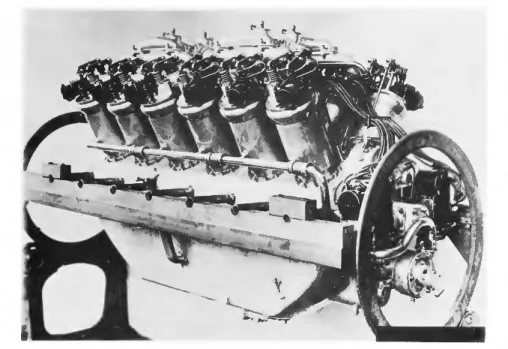
Kirkham's new engine, first known as the D-1200 (Figure 9) had a half inch greater bore and stroke (4/2 by 6 in.) than the AB, displaced 1,145 cubic inches against the new Hispano's 1,127, and was intended to furnish 400 bhp and run at an unheard-of 2,500 rpm—all this with a designed weight of only 625 lb.
From today's viewpoint, one wonders at the daring and foresight of Kirkham, who brought out a fighter engine of 400 bhp at a time when a proposed United States Standard Engine (known as the Liberty), be- lieved to cover all existing needs, was planned as a V-8 of between 250 and 275 hp. The fact that the big new Hispano-Suiza eventually materialized as a direct-drive, slower turning (1,800 rpm) engine did not impress Kirkham; or, if it did, he paid no heed, for so possessed had he now become by his inspiration that he no longer was to be deterred by technical difficulties or problems with metallurgy.
The greatest improvement over the AB was in the flow of the exhaust gases. In the D-1200 the valves were actuated by two camshafts, one for the exhaust and one for the inlet valves. Consequently, all exhaust valves could be located on the outside of each cylinder block, where they opened into individual ports for unhampered escape of burnt gases.
The exhaust ports fitted into a big collector which ejected the gases
FIGURE 9.—Curtiss D-1200, 400 hp, 1917. (Photo courtesy of U.S. Air Force Museum.
Smithsonian photo A-4618A.)
directly upward through a large central chimney at each side of the engine. Carburetion was by a new Ball and Ball Duplex type DVA-3, and the two magnetos were Ericsson-Berling model D-66 X-4. Each magneto fired one bank of cylinders, but this procedure was not well thought out—a magneto failure resulted in an immediate loss of half the engine power. The A.C. spark plugs were all located on the inside of the V formed by the two banks of cylinders. As in the AB model, the crankshaft was supported by four main bearings, but there was an added fifth outboard bearing in front of the reduction gear for extra support.
Inaugurating a new breakthrough in aero engine technology, a me- chanically driven, partly built-in supercharger was to be installed at the rear of the new engine. It was to be driven by a long shaft running through the center of the V and to be geared to the reduction gear at the
FIGURE lO.-Curtiss K-6, 150 hp, 1919. (Smithsonian photo A-4991A.)
front of the engine. A friction clutch was inserted near the front end of the driving shaft to eliminate all possibility of any torsional or accelerating forces being transmitted to the supercharger impeller.
Four mechanically driven superchargers built by General Electric were ordered in 1917. Two of these were requisitioned by McCook Field's engineering division, at that time busy with development of the exhaust- driven turbosupercharger for the Liberty engine. The other two units were delivered to the Curtiss Company, but development work on the superchargers lagged because the engine itself demanded every possible effort from Kirkham and his team. Later, the supercharger was found to be unsatisfactory, but the idea for its use was significant in that it showed Kirkham's early preoccupation with a feature that would come into use a full ten years later.
FIGURE 11.—Curtiss K-12, 375 hp, 1918. (Photo courtesy of U.S. Air Force Museum.
Smithsonian photo A-4618.)
The new engine soon became truly identified with Kirkham by its official designation, the K-12; and usually it was referred to as the Kirkham or Curtiss-Kirkham engine. The prototype K-12 was bench- tested (in the last week of 1917) at a weight of 625 lb, as designed.
A six-cylinder unit, the K-6 (Figure 10), was developed along parallel lines. It really was half a K-12 (without reduction gears and other pretentions toward high power) that was rated at 150 hp at 1,700 rpm.
Undoubtedly, Kirkham had become fully aware that his K-12 (Figures 11, 12), with its very small frontal area and high power, stood unchal-
FIGURE 12.-Curtiss K-12, 1918. (Smithsonian photo A-4594A.)
lenged; and, afraid lest his brainchild be wasted on some cumbersome or indifferent airplane, he undertook at once to design a fighter that would be able to use the K-12 to its best account—a battle plane that
would outperform any existing airplane as completely as he believed the K-12 would eclipse every existing engine. Here was a case of a single designer being able to devote his talents not only to developing a new, untried engine but also to designing a new airplane that would utilize it.
T h e new airplane h a d characteristics that were extremely progressive a n d original, following the true Kirkham touch. Full advantage was taken of the low frontal area of the K-12, with the fuselage closely tailored a r o u n d the engine. T h i s was a new departure in design, as h i t h e r t o the engines somehow h a d been fixed o n t o the airplanes. A possible exception was the French SPAD, which was built to take full advantage of the compactness of the Hispano-Suiza, a n d it may have inspired Kirkham to some extent. Pure speed h a d not been uppermost in the minds of aircraft designers u p to that time, as so many other qualities h a d to be considered. T h e trend toward the combining of a small, powerful engine with a wholly streamlined aircraft for obtaining higher speeds h a d started, however, in 1917.
Kirkham's airplane is described in the first edition of the Aircraft Yearbook (1919, page 121): " T h e craft is a t r i u m p h in streamlining.
N o t a square inch of the machine, from tail skid to exhaust pipes, has been omitted from the careful plan of shaping, which has cut resistance to the m i n i m u m . "
W i t h high speed now secured by high power, complete streamlining, a n d a small engine, Kirkham proceeded to e x p a n d on the theme by using three wings on the plane's fuselage. Kirkham believed that a triplane would increase maneuverability a n d climbing capability. T o top it all, the fighter was to be a two-seater, with the pilot having two synchronized guns at his command a n d with the gunner, in the rear, having two movable guns, thus adding m a x i m u m firepower to highest speed a n d o p t i m u m climbing ability. T h i s promised to become by far the most formidable airplane designed since the beginning of the war, and more than others it deserved the name of " b a t t l e p l a n e " that was applied to it.
Capitalizing on the big promise of the K-12 a n d the triplane, Willys approached the U n i t e d States Navy and pressed for a big contract as soon as possible. I n spite of entreaties from the developers of the geared Liberty, then on test, that that engine was more suited for its needs, the Navy did not have the fixed idea for "one standard engine in one standard plane." O n 30 March 1918 the Navy placed an order with Curtiss for two triplanes a n d four K-12 engines.
O n 5 July 1918 the K-12 went u p for the first time, powering the
triplane on its maiden flight. Roland Rohlfs, Curtiss test pilot, was at the controls, and his take-off was significantly short.
Progress of both airplane and engine was watched with keen interest.
In the first flights the four-blade propeller braked the engine at 1,900 rpm, restraining power and speed, so a new two-blade propeller was fitted. The side radiators cooled too much, so smaller ones were installed; but then the engine overheated on the fast climbing tests.
The problem was solved by adapting a by-pass device that eliminated use of part of the larger radiator during horizontal flight.
It was clear from the first flights that the triplane stood up magnifi- cently to its claim for speed and climb; and it already had shown itself capable of outdistancing a DH-4 with ease. Rohlfs claimed that the climb was in the neighborhood of 2,000 ft/min, and maximum speed was assumed to be around 150 mph. Both figures represented perform- ances greater than any other airplane had been known to achieve.
The first official flight finally was made on 19 August, and trials were held from 1 September to 5 September. The witnessing Navy officers, Holden C. Richardson and C. N. Liqued, may hardly have believed the figures when it was shown that the 18-T—as the triplane was now designated—on its first official flight had reached a best speed, over a measured course, of 162 mph in full military trim. The previous officially recognized speed record had been set at 126 mph, in September 1913.
The first triplane (Figures 13, 14) was given Bureau No. A-3325; the second was assigned the number A-3326. After the first official trials the Navy was willing to order 750 K-12 engines at once, but the Bureau of Aircraft Production decreed that this order was not to interfere with the priority of materials destined for the Liberty engine, the mass pro- duction of which already was underway. But to the great chagrin and disappointment of everyone concerned, including the naval officers delegated at the Curtiss plant to supervise manufacture, no large orders were placed.
The reasons for the Navy's reluctance were valid enough. The K-12 had not yet passed a 50-hour acceptance test; also, interest in triplanes was on the wane at that time. Allied authorities had stated that tri- planes were not satisfactory, and certainly not for two-seat fighters, because of poor visibility and lack of stability as a gun platform. It was clear also that the war was nearing its end and the time for large con- tracts was past.
The Army had already approached Kirkham for a biplane version of the 18-T to be built along similar lines; and the Navy also had stated
FIGURE 13.-Curtiss-Kirkham 18-T Wasp triplane, about 1919, with Curtiss K-12 engine, 1918. (Smithsonian photo A-4597.)
a preference for a biplane—if possible, a seaplane—and after the Sep- tember tests it had recommended conversion of the triplane into a sea- plane. As a result, in the summer of 1919 the A-3325 was converted, using floats of the N-9 type, and it reached 126 mph during tests. In April 1920 this aircraft set a world's seaplane speed record at 138 mph.
Later, both triplanes were prepared as racing landplanes, with the aft seat faired in.
The Army first had evinced interest when it had asked Curtiss to lend it the Navy's A-3325 for test flights. This plane was flown at Wilbur Wright Field on 18 September but it showed the same troubles with overheating, due to the smallness of the radiator, as it had on the earlier Navy tests. In the meantime, the Army's engineering division had written a report on the biplane design the Army had asked for.
This report, based on the data given by the Curtiss Company and signed by Alexander Klemin, bears the date 13 August 1918 and the serial number 267.
Criticism was made of the single gun on the turret for the observer, though there was another gun on a flexible mount in the floor. When the time came to evaluate the K-12 engine, it was noted that 400 bhp was claimed at 2,350 rpm on a 6:1 compression ratio with a weight of
FIGURE 14.—The 18-T triplane with floats. (Smithsonian photo A-4597A.)
680 lb. T h e weight figures were stated as being "Much below present best practice. T h e r e either is an error in the weights or the motor may have to be carefully watched." T h e phrase "present best practice"
meant, of course, the Liberty engine. It also was noted that the weight of the K-12, given as 625 lb in J u n e 1918, had been raised to 660 lb and finally, in August, to 680 lb. Curtiss then was given Order CS-152, for two biplanes a n d two triplanes. One plane of each type was to be stati- cally tested to ascertain the true limits of strength, while the others were to be thoroughly tested in flight. T h e static tests of the first triplane, delivered to McCook Field in February 1919, revealed serious weak- nesses in several components. T h e first biplane was delivered in J u n e 1919, after it h a d been displayed in New York at the Madison Square Gar- den show in March. It received n u m b e r SC-40454 a n d became the P-86. Its crash, soon afterwards, ended the Army's interest in the type.
Meanwhile, the Wright-Martin Corporation h a d been experiencing difficulties in its efforts to bring the Hispano-Suiza to mass production.
It was clear from the start that the design of that engine was not one that could be copied easily, and considerable delays were suffered for different reasons. T o make things worse, new specifications for im- proved ratings were coming from France, raising the power first to
FIGURE 15.—Hispano-Suiza Type H, 300 hp, 1919. (Smithsonian photo A-4594B.)
180 hp, then to 200 hp, and later to 220 hp. It was not noted, however, that as horsepower ratings went up, reliability went down.
In the face of these conflicting interests, Wright decided, wisely, to stay with the original design and direct all efforts towards bringing the 150-hp model to production as soon as possible. But not much headway was made at first. The chief difficulties lay in the extreme stringency of the specifications for the different materials and in the excessively small tolerances to which every piece had to be finished, making the work more difficult than watchmaking. The famous cast-aluminum cylinder blocks were giving nightmares to all concerned, and most of the troubles were solved only when the company had established its own aluminum foundry, working at superior refinements. Production finally started at the beginning of 1918, but by then the proud "Hisso"
fighter engine of 1916 had become suitable for trainer duties only.
When the blueprints for the new 300-hp model finally arrived, prepa- rations were made promptly for its speedy production, but the solving
FIGURE 16.— Crankshaft and propeller shaft, showing reduction gears, of Curtiss K-12, 1919. (Smithsonian photo A-4594D.)
of problems similar to those with the smaller types resulted in the new model (Figure 15) not being ready for production until near the end of
1919. Still, the fact remains that the small Hispano finally was pro- duced successfully in satisfactory numbers. Two British attempts to improve on the Hispano form of construction—the Siddeley Puma and the Sunbeam Arab—had not been successful, and subcontractors were running into trouble everywhere. (The fitting of steel cylinder liners in aluminum blocks still is considered a major problem by automobile manufacturers today.)
Against this background it is easier to understand why the K-12, which was intended to outperform the Hispano in many ways, encoun- tered numerous difficulties. The main troubles were related to the reduc- tion gear, the large aluminum casting, and the crankshaft (Figure 16).
The reduction gear troubles were particularly irritating because they were a necessary evil. The problem basically stemmed from the oppos- ing relationships between the engine, which, in becoming lighter and smaller, could run faster, and the propeller, which gained in efficiency by running slower. In the case of the propeller, the rotational speed was further limited by enormous problems that arose when the velocity of the tips reached the speed of sound. This put an upper limit to propeller speed at about 2,000 rpm. A prudent safe maximum being considered at the time was around 1,800 rpm. The only solution lay—and still lies—in the provision of a form of gearing which reduces
the speed of the propeller shaft of the engine to a figure better suited to propeller efficiency. The problem is as old as aviation itself. The Wright brothers used, from the first, a crude but efficient form of gear- ing with bicycle chains.
The Hispano-Suiza was readily adaptable to high-speed running. The original model of 150 hp had been enabled to turn out increasing power ratings by the simple expedient of making the engine run faster. With crankshaft speeds of up to 2,150 rpm coming into use, the introduction of a reduction gearing became imperative. But at the same time it was found that the gearing was a delicate and tricky affair, and seizures were frequent. The big, 300-hp Hispano had been conceived in geared and ungeared form, but the geared form was not followed up and the crank- shaft speed of the direct-drive production model was kept down to 1,800 rpm.
The K-12, which from the onset was designed for highest power and smallest size, could not dispense with the gears, which had a reduction ration of 5:3 (or 0.6), but here, too, continuous trouble-free running could not be attained in spite of the addition of a fifth bearing in front for the support of the pinion.
The integral construction of crankcase and water jackets in one aluminum casting, while making for great saving in weight and theo- retical rigidity, really was a type of construction that bordered on the impossible. The blocks were cast at the Buffalo foundry of the Alu- minum Company of America, which worked diligently and conscien- tiously to produce good castings, but such a complicated and large casting was beyond the art of the time. The results: too many blocks condemned because of warping, too many misruns, and too much porosity, doubtless due to the high pouring temperatures used in the attempt to avoid misruns.
The crankshaft, supported on four bearings and with counterweights for static balance only, was not reliable and breaking occurred easily.
The situation could not be improved, and an exasperated Kirkham ended his attempts by refusing to strengthen the design and preferring to blame the material as faulty.
The first of six attempts to run an endurance test as required by the armed services was started at the Buffalo plant of the Curtiss Corpora- tion on 9 August 1918 using K-12 engines 7, 8, and 9. The normal schedule to which any engine had to be submitted consisted of ten separate five-hour runs. The first half hour of each run was at full throttle and rated power, while the remaining four and a half hours were at 90 percent of rated power. Engines 7 and 8 weighed 665 lb,
dry; engine 9 had a 24-lb counterweight added in the center of the crankshaft, raising its dry weight to 689 lb.
Test 1, with engine 8, was discontinued after 1 hour 36 minutes, full- throttle, when connecting-rod bearing 2 burned out because of break- age of the oil manifold.
Test 2, with engine 7, ended after 20 minutes of the third five-hour period (i.e., after 10 hours 20 minutes) when six teeth of the reduction gear on the crankshaft broke.
Test 3, with engine 8 after its oil manifold had been repaired and strengthened, was discontinued after only 4 minutes running when cylinders 1, 3, and 5 ceased firing. The breakdown occurred when parts of an auxiliary air valve of the front carburetor were sucked into the cylinders, holding the valves open and bending the valve stems.
The auxiliary air valve was then redesigned.
Test 4 was the third attempt with engine 8, after it had been put in condition again. This time the K-12 ran well and hopes soared, but after 21 minutes of the third five-hour period the articulating boss on master connecting-rod 6 broke; as a result, the crankcase cracked between cylinders 5 and 7 and the base of cylinder 5 ;was damaged.
This test marked the end of engine 8. The boss on master rods was strengthened on the other engines.
Test 5, with engine 7, was an all-out effort to make the 50 hours, but it was marred by numerous interruptions. The first stoppage came after 10 minutes running when the tachometer drive housing broke.
It also was discovered that one camshaft bearing had broken. Heavier bearings were installed and the test was resumed, but after 5 minutes more there was a second interruption—the right-hand magneto drive shaft had frozen to the bushing in the tachometer drive gear housing.
When this trouble was cured the engine went well for the remainder of the first five-hour period. After 20 minutes at full throttle in the second period there was another interruption when the clamping bolt of connecting-rod 2 broke away. The bolts were replaced with others having thicker heads. A fourth interruption, after 3 hours 8 minutes, was caused by the breaking of the lock screw for the tappet of the rear intake valve of cylinder 11, letting the valve drop into the cylinder.
This lock screw had been bent in tightening. Lock washers were fitted and the test was resumed. After half an hour at full throttle and 4 hours 37 minutes at 90 percent power, the fifth interruption occurred when the oil line to the pressure gage at the crankcase cracked. After another 4 hours 9 minutes running, this test was at last discontinued when a lock nut on the rear of the propeller shaft broke. This time the engine
FIGURE 17.—Assembly of pistons and connecting rods, Curtiss K-12, 1919.
was ruined beyond repair because the propeller shaft shifted out. As the reduction gears on the propeller shaft and crankshaft were of the herringbone type, the propeller shaft pulled the crankshaft with it.
This broke the oil feed line to the bearing and interrupted the oil feed to connecting-rod 2, causing its bearing to burn out together with the crankpin and thus spoil the crankshaft. This was the end of engine 7.
Test 6, with engine 9, was interrupted after half an hour wide open and 2 hours 57 minutes at 90 percent power when an exhaust valve tappet lock screw loosened on cylinder 12 and the valve dropped into the cylinder. The valve tappets then were more carefully fitted and all lock screws were wired to prevent loosening. A new start was made but the test was interrupted after 25 minutes of the second five-hour period when the A.C. Titan spark plugs began to leak badly. All plugs then were replaced by a complete set of Bethlehem Aviation plugs.
FIGURE 18.—Cylinder head casting of Curtiss K-12, 1919, with cylinder sleeves, cam- shafts, and valve gear assembled. (Smithsonian photo A-4602A.)
The test was discontinued after 51 minutes of the third five-hour period when two rear camshaft bearings and three teeth of the reduction gear on the crankshaft broke.
The report ended on an optimistic note: "The design of the engine is excellent and it is believed to be capable of passing the 50 hrs test without difficulty when the troubles mentioned are overcome." The results of the different tests showed an average power of 389 hp at 2,250 rpm and a maximum of 418 hp at 2,550 rpm. Compression ratio was 5.5:1. In the official report the engine was mentioned as Kirkham- Curtiss model D-1200, rated at 375 bhp at 2,250 rpm.
Toward the end of 1918, or very early in 1919, two new engines, numbers 14 and 15, were sent to the engineering division at McCook Field to be submitted again to a 50-hour endurance test. Engine 14 broke its crankshaft during the preliminary calibration test, so only engine 15 was given a test, which is described in McCook's Serial Report 811 of 25 April 1919. At the request of the Curtiss Company, the engines were not run above 2,400 rpm, which was about the peak of the power curve. The average rated power was 396 bhp at 2,250 rpm, with a maximum of 406 hp at 2,420 rpm.
The report concluded with the statement that the engine, even though well designed and of high power for its weight, appeared to be some- what complicated and of difficult maintenance. The tested engine suffered from water leaks throughout the duration of the tests, which terminated with a cracked cylinder jacket. The report ended on a note
FIGURE 19.—Curtiss Eagle, 1919, powered by three Curtiss K-6 engines.
(Smithsonian photo A-4602E.)
less optimistic than the previous one: "The [K-12] engine is still in the experimental stage and is not as yet suitable for actual service."
It has sometimes been stated that the K-12 was turned down because the government was concentrating on the Liberty engine. This is only partly true. The United States Navy retained its interest throughout the K-12 engine's career. Besides, the Curtiss Company never had been associated with the design or production of the Liberty. Undoubtedly it would have, had it not believed that it had something better. A great part of the millions of dollars spent on the American aeronautical effort was poured into the simultaneous attempts to mass-produce and improve the Liberty engine, a high-power design based on proved con- structions. Though these efforts made it possible for America to get aero engines to the battlefront before November 1918, when the Armistice occurred, the men actively connecetd with the K-12 never could shake off the belief that the United States would have had a superior product had a fraction of the millions been put into the development of Kirkham's aluminum-block design.
After the Armistice, the interest in experimental airplanes and engines waned rapidly, and no new contracts were made for development or
FIGURE 20.—Curtiss Oriole for Amundsen polar expedition, with Curtiss K-6 engine, 1922. (Smithsonian photo A-4602F.)
production of the K-12; however, existing contracts were not canceled.
With the advent of peace, men were confident that weapons would be abolished for all time and the aviation manufacturers were eager to get going with plans for new commercial aircraft, of which great things were expected. The Curtiss Company, for one, brought out a beautiful new trimotor transport, the Eagle, that was powered by three 150-hp K-6 engines (Figure 19). Another use for the lower-stressed, direct-drive K-6 was found in a new three-seat sports plane, the Oriole (Figure 20), Which was also available with the war-surplus OX-5.
Curtiss President Willys was even more anxious now to get the K-12 past its teething troubles and to turn it into a salable product. He decided to call Finlay Robertson Porter to assist Kirkham in bringing the costly experiments with the K-12 to an end as soon as possible. In 1918 Porter had been chief motor engineer at McCook Field, and he had acquired some reputation in the automobile field. Porter and Wright's chief engineer, Crane, were old competitors. They had marketed, respectively, the FRP and the Crane-Simplex, the two most expensive motor cars built in the United States during 1916. Porter also was an old acquaintance of Willys, having worked with him in 1915 on a racing car powered by a Knight engine.
But Kirkham was not willing to accept any kind of assistance or supervision. The antagonism thus created between him and the Curtiss management culminated in his resignation from the Curtiss Corporation early in 1919. He then founded his own firm, Kirkham Products, which was devoted to consulting engineering in aeronautics and which would be responsible for a number of highly original airplanes and engines.
His assistant, chief engineer, T. S. Kemble, left Curtiss in April. Kirk- ham was retained for a time as consultant at Curtiss's Garden City plant to advise on the triplane, the trials of which were continuing; but his connection with the K-12 was severed forever, and Curtiss no longer was to use his name in relation to the design or use of the engine. The fate of the K-12 came completely under the responsibility of Porter, who became chief motor engineer at Curtiss.
About twenty K-12 engines had been built and several of these were still around; so, when the first big postwar aero show opened in Madison Square Garden on 1 March 1919 the K-12, rated at 375 hp, was exhibited on the Curtis stand. The Army's 18-B, now with the name Hornet, also was shown. For the Hornet, a maximum speed of 163 mph was claimed, and a speed of 80 mph was mentioned for normal use, which needed much less than half the maximum engine power. It perhaps was piously hoped that the K-12, if sold, would not be used too much at full throttle. At that time there were no type certifications or FAA inspections, and manufacturers were free to offer any product;
but there is no record of any person or any service in the United States buying one of those "fastest planes in the world," as they then un- doubtedly were, nor was the K-12 sold for installation in any other civil or military airplane in the United States during that year.
Through vigorous publicity and the efforts of a special sales delega- tion some commercial success was achieved in South America. One K-12 was installed in a triplane flying boat, ex-Navy A-2277, which was used for exploration, and one K-12-powered 18-T triplane was sold to the Bolivian government, of which more later.
The 18-T triplane had been given the name Wasp, and, by one of fate's tricks, the names Wasp and Hornet were the very ones that would be assigned to the two engines that were to cause, eight years later, the displacement of the K-12's successors in military airplanes.
It had been an idea of Chief Test Pilot Roland Rohlfs, who remained enthusiastic about the triplane's climbing abilities, that an attempt could easily be made to win the world's altitude record. Triplane A-3325 (or possibly A-3326), still in abeyance at the Curtiss Garden City plant, was converted for that purpose with enlarged two-bay
FICURE 21.—Curtiss 18-T Wasp with Curtiss K-12 engine, destined for Bolivian air force, October 1919. (Smithsonian photo A-4602G.)
wings. A specially prepared K-12 with a higher compression ratio was used. W h e n the first attempts were made, two or three engines burned out because the scavenging oil p u m p in the forward part of the engine failed to work at a high angle of climb.
I n July 1919 an altitude of 30,500 ft was reached, and finally, on 18 September, with engine 13—which h a d produced 465 b h p at 2,600 r p m on a compression ratio of 6:1 d u r i n g a bench test in J a n u a r y — R o h l f s attained a height of 34,910 ft and claimed a world's record. T h e first part of the climb was made with a nursed engine until 31,000 ft was reached, b u t then, due to the steep climbing angle m a i n t a i n e d a n d the lessened density of the air, the plane began to stall a n d d r o p p e d 600 ft.
Rohlfs then applied full throttle and lowered the angle of climb for the remaining 4,000 ft. T h i s record was never officially recognized as a world's record by the Federation Aeronautique Internationale, ap- parently because the barograph, after the necessary corrections, did not show a sufficient improvement over the preceding record, made on a French N i e u p o r t with a special high-compression Hispano-Suiza of 300 h p .
The climbing and high-flying demonstrations of the Wasp triplane were decisive in convincing the Bolivian authorities of the worth of that aircraft. They were anxious to have an air force like everybody else, but had been confronted by the problem of having their capital city high in the Andes mountains, with its airfield, El Alto, situated at
13,500 ft above sea level. Prior to the Bolivian government's purchase of the Curtiss Wasp (Figure 21), and in spite of some earnest attempts, no airplane had been able to take off from that airfield, but with the arrival of the K-12-powered triplane the situation changed dramatically.
On 17 April 1920, in the able hands of Donald Hudson, who was on loan from the Curtiss Company to the Bolivian government, the Wasp took off from El Alto with such ease and grace that the assembled officials were wildly enthusiastic. The Bolivian Air Force was created on the spot, and Donald Hudson was made a lieutenant colonel and chief pilot.
The first flights in Bolivia were phenomenal. A short time after the first take-off Hudson reached 31,000 ft, and on 12 June he crossed the Andes, flying at 30,000 ft. Unfortunately, the elation was not to last long. In the following year, on 19 May 1921, Hudson made an over- land flight of 160 miles to Oruro in 75 minutes, but on the return flight the inevitable happened—the K-12 gave up, and the plane crashed and was destroyed beyond repair, but with no injury to the pilot. The Bolivians, who by now had become aware of the experimental status of their purchase, did not accept the loss graciously; they felt cheated, and the contract with Hudson and Curtiss was canceled. Five years later, however, relations with Curtiss became cordial again when Jimmy Doolittle flew a Curtiss Hawk fighter to El Alto field and sold several such craft to the Bolivian government.
Development of the Curtiss C-12
Meanwhile, the Curtiss Company, under the presidency of John North Willys, was not sure how to proceed with the K-12. Apart from the preparations for the height-record attempts, it appeared unlikely that more work would be devoted to that engine.
In the summer of 1919 Clement Keys, Curtiss's vice president, began a tour of Europe as a member of the American aviation mission. On that trip he visited the most important aircraft and engine manu-
FIGURE 22.—Sectional drawings of Napier Lion, 450 hp, 1919.
(Smithsonian photo A-4619.)
facturers in England and France, and he quickly became aware of some interesting situations in regard to aero engine development. In Eng- land, for instance, development of water-cooled engines had virtually stopped, except for the broad-arrow Napier Lion (Figure 22), and any money made available was being spent on perfecting the high-power air-cooled radials that had been designed in 1917 and 1918. In France there was such a large stock of aero engines on hand that development had stopped altogether, and the only activity was concentrated on main- taining normal standards of reliability for the number of such engines as were needed. The leading engine there was the 300-hp Hispano- Suiza, the same model that was being readied for service by Wright Aeronautical in the United States.
Keys discovered that no engine in Europe could match the K-12 in regard to power, low weight, and small size. Also, he saw that several French airplane manufacturers were adapting the new 300-hp Hispanos to modified prototype fighters for attacks on the world's speed record, set in 1913. Indeed, that record was broken in October 1919 by a Nieuport-powered, specially prepared single-seater with clipped wings that flew at 167 mph. In contrast, the 162 mph attained by the Curtiss triplane in full military trim showed the promise of the K-12 for speed work, even if it was not then adaptable for commercial use. Keys argued that the speed record should be brought to America, and he wrote to Willys that he thought it advisable to continue the development of the K-12, the fate of which was hanging in the balance.
In April 1919 Porter had started on his assignment at the Garden City plant; and in May he took over direction of the operations in Buffalo, where the K-12 was being tested under direction of Arthur Nutt, the firm's young motor test engineer of whom we will hear more. Porter took a good look at the K-12, was able to form an opinion about the principal weaknesses of the design, and proceeded to redesign the engine accordingly.
The changes introduced in Porter's new design thus were a reflection of the experiences with the K-12. The large aluminum casting was eliminated by separating the cylinder block from the crankcase and bolting them together, which was more in accordance with Hispano practice. This arrangement eliminated the tooling problems that had appeared with the integral castings, and it eased maintenance to some extent because repairs to any cylinder could now be handled by remov- ing a cylinder block instead of removing the whole engine, which the K-12 type of casting demanded.
The crankshaft was changed to a seven-bearing type and the counter- weights of the K-12 crankshaft were eliminated, but since the cylinder
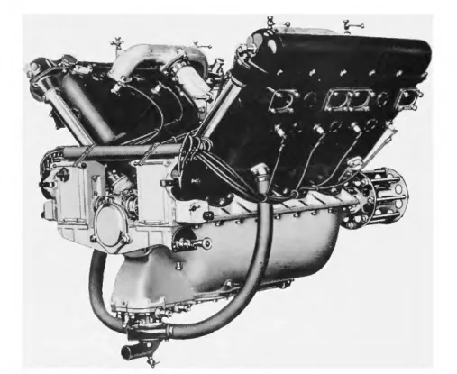
FIGURE 23.-Views of Curtiss C-12, 400 hp, 1920.
(Smithsonian photos A-4881C, A-4879.)
FIGURE 24.—Crankshaft, reduction gear, propeller shaft, and propeller hub of Curtiss C-12, 1921. (Smithsonian photo A-4619F.)
blocks were not redesigned the total bearing surface could not be aug- mented. Consequently, the introducing of more bearings was largely a step backwards.
The spark plugs, which on the K-12 had been placed side by side on the inside of the V, were relocated to both sides of the cylinder block so that six plugs were on the outside and six on the inside of each cylinder bank facing each other. Now, the failure of a magneto would not cause the loss of half engine power as with the K-12.
New carburetors of the Claudel-Hobson double-inverted type were installed. The magnetos were Berkshire D-6s, each firing one A.C.
plug per cylinder.
The large exhaust collector was eliminated, obviously because it burned out too easily. All the new engines and the remaining K-12 units were fitted with short individual exhaust stacks, one for each exhaust orifice, so that there were twelve stacks on each side of the engine, a distinctive feature of all Curtiss water-cooled engines ever since. One source of trouble, the reduction gearing, was retained on the new design, but there was no way to eliminate it without suffering a great reduction in power.
The new engine (Figures 23-25) became known as the C-12. It was rated at 400 hp for 2,250 rpm, and the weight, at least for the first units, was given as 675 lb, about that of the K-12. The six-cylinder K-6 was redesigned along the same lines and renamed Curtiss Six, or C-6. It had a rating of 160 bhp at 1,750 rpm and was to have a long and suc- cessful life, without further modifications.
FIGURE 25.—Pistons and connecting rods of Curtiss C-12, 1921.
(Smithsonian photo A-4624G.)
The first C-12 engines were ready at the end of 1919, and the first unit was tested in January 1920. With the commercial market still in mind, Curtiss gave the new engine its first publicity showing at the New York aero show in March 1920 as the power plant of a new version of the Eagle transport, the Eagle II—the same airplane that had flown in 1919 as a trimotor with three K-6 engines. The airplane made its new appearance with two C-12 engines installed.
Roland Rohlfs piloted the new Eagle for one test flight, but during take-off the shaft driving the water pump seized on the left engine, which then lost all power within seconds. The plane barely cleared a building, actually rolling its wheels on the roof. This was the only flight of the Eagle II, as the C-12 engines were removed immediately.
But it was not the end of the Eagle. In 1920, when the commercial value of the new projects was beginning to appear doubtful, the Eagle was offered to the Army for use in a project for a day-bomber with a single Liberty engine. Three such bombers were ordered, and the existing Eagle was immediately converted with a single Liberty engine and delivered to Mitchell Field. No others were built.
About the time the Eagle II made its unsuccessful test flight, both Willys and Porter were becoming convinced that there was no future in the development of high-powered aero engines, which apparently were unwanted. The Liberty had stolen a march on all new designs, and there were too many Liberties in storage. Both men withdrew
from the Curtiss Company to devote their talents a n d energies toward the promotion of the automobile industry. Porter again would market America's most expensive motor car, the Porter. T h e products of Willys are well known.
T h e C-12 was to be saved from oblivion by the enthusiasm of Clement Keys, Curtiss's new president. Keys decided to bury all attempts at possible commercial use and to go ahead with a program for high-speed flying, using all the qualities of the new C-12 engine toward that purpose.
T h e first i m p o r t a n t opportunity for the C-12 to show its mettle presented itself with the first postwar race for the Gordon Bennett Cup.
T h i s event, to be held in France in the summer of 1920, promised to become one of international importance. Each competing country was permitted three entries. T h e race itself was to be a pure speed event over a course of 300 km (186.5 miles). Each contestant could choose the time of day for his entry.
For Curtiss, the winning of the Gordon Bennett C u p was particularly desirable, as a Curtiss plane a n d engine h a d won the first such event in 1909 and derived much prestige from it. Officials at Curtiss decided to make a special effort, a n d the victory appeared well within reach because the decisive element, the engine, already was at hand.
A special committee met in March 1920 at a luncheon in Dayton at the invitation of Texas oil millionaire and aviation enthusiast S. E. J.
Cox, who already h a d entered an airplane under the auspices of the Aero Club of Texas. A contract between Cox a n d the Curtiss Corpora-
tion that called for the building of a racer capable of at least 200 m p h was signed on 19 J u n e .
Apart from Curtiss, two other contestants from 'the United States entered racers that represented completely different approaches to the problem of obtaining high speed. An entry by the U n i t e d States Army Air Service represented the expression of the "power is everything"
philosophy. T h i s was a Verville VCP pursuit biplane, originally built to carry the 300-hp Hispano b u t for this occasion fitted with Packard Engineering Vice-President Jesse Vincent's latest masterpiece, a 12- cylinder blockbuster based on the Liberty but displacing 2,025 cubic inches. At McCook Field the new engine h a d been thoroughly tuned, the compression raised, and a special fuel concocted, resulting in a power on the bench of well over 600 b h p . T h e reformed pursuit, designated the V C P - R , was declared capable of 200 m p h .
T h e third American entry reflected the other extreme of design. In this airplane, built at the Dayton-Wright Company where Orville
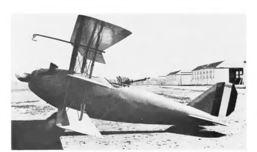
FIGURE 26.—Curtiss-Cox Texas Wildcat, 1920, with Curtiss C-12 engine, 400 hp.
(Smithsonian photo A-4619A.)
Wright was consultant, extreme fineness of penetration had been the goal, making up for a lack of engine power. The Dayton-Wright racei was a full cantilever monoplane with wings of variable camber. The en- gine, built by Hall-Scott, was a six-cylinder, in-line Liberty of maximum 250 hp, making this racer the lowest powered airplane entered—but the in-line engine permitted the least possible frontal area. Another special feature was the retractable undercarriage, a novelty at this time. The pilot was enclosed so completely in the fuselage that he had limited visibility, only through a window at each side. This racer, like the VCP-R, was advertised as being capable of 200 mph.
Curtiss, of course, had the C-12, giving 427 hp at 2,250 rpm—without even being pushed very much—and capable of good durability with full- throttle running. Not content to play up only the engine, Curtiss also gave the airframe maximum attention—perhaps too much. Under the direction of William Gillmore, the Curtiss engineers, carried away by the prevailing high spirits, designed and built two extremely small racers around the C-12 engine. Mrs. Cox named them Texas Wildcat and Cactus Kitten (Figures 26, 27). The first flight was made on 25 July, five weeks after the signing of the Cox contract. As usual, the undauntable Roland Rohlfs was in the cockpit. With large test wings, a speed of 183 mph was reached, but a special minimum-surface wing already was in the works and with these special race wings the maximum speed was calculated as 214 mph. These were certainly the fastest airplanes of their time, and the Gordon Bennett Cup appeared as good as won. As events turned out, one of the Curtiss racers easily could have won with the large test wings or any sort of wings, but such was the furore aroused
FIGURE 27.—Drawings of general arrangement of Curtiss-Cox Cactus Kitten, 1920, powered by Curtiss C-12 engine. (Smithsonian photo A-21253.)
by the press that it was thought to be of no use to enter a racer not capable of at least 200 m p h .
T h e first tests of the Curtiss racers were held at Roosevelt Field, which was not large enough to test the maximum-speed wings. As time was r u n i n g out, the decision was made to ship the two planes to France, in the belief that the big, smooth airfields near Paris would make testing a n d adjusting easy. After the usual delays with shipping and customs, the machines arrived at their assigned airfield, still in crates, a bare ten days before the race. After another five days of work the Texas Wildcat was ready for a first test a n d R o l a n d Rohlfs took his place at the controls.
T h e C-12 was started and warmed up. Soon Rohlfs gave the signal and applied full throttle, b u t at once he found himself in a distressing situation. T h e geared-down, fixed-pitch propeller h a d been calculated to pull h a r d at 200 m p h , b u t at zero airspeed its pull was hardly notice- able. Add to this the effect of wings which did not lift u n t i l an im- pressive speed was reached, and the result can readily be imagined. T h e engine roared its utmost b u t the start was frustratingly slow.
Rohlfs used u p the entire length of the airfield a n d an adjoining piece of farmland before he finally was able to get the unwilling plane air- borne. He continued at a slight climb u n t i l the airplane reached a high speed a n d became fairly controllable. U n d e r continuining full